
 Open Access Article
 This Open Access Article is licensed under a Creative Commons Attribution-Non Commercial 3.0 Unported Licence
A microfluidic labyrinth self-assembled by a chemical garden†
Sergio
Testón-Martínez
 *a,
Teresa
Huertas-Roldán
a,
Pamela
Knoll
a,
Laura M.
Barge
b,
C. Ignacio
Sainz-Díaz
a and
Julyan H. E.
Cartwright
*ac
*a,
Teresa
Huertas-Roldán
a,
Pamela
Knoll
a,
Laura M.
Barge
b,
C. Ignacio
Sainz-Díaz
a and
Julyan H. E.
Cartwright
*ac
aInstituto Andaluz de Ciencias de la Tierra, CSIC–Universidad de Granada, 18100 Armilla, Granada, Spain. E-mail: s.testonmartinez@gmail.com; julyan.cartwright@csic.es
bNASA Jet Propulsion Laboratory, California Institute of Technology, 4800 Oak Grove Drive, Pasadena CA, USA
cInstituto Carlos I de Física Teórica y Computacional, Universidad de Granada, 18071, Granada, Spain
First published on 1st November 2023
Abstract
Chemical gardens, self-assembling precipitates that spontaneously form when a metal salt is added to a solution of another precipitating anion, are of interest for various applications including producing reactive materials in controlled structures. Here, we report on two chemical garden reaction systems (CuCl2 and Cu(NO3)2 seed crystals submerged in sodium silicate) that produced self-assembled microfluidic labyrinths in a vertical 2D Hele-Shaw reactor. The formation of labyrinths as well as the specific growth modes of the precipitate were dependent on the silicate concentration: CuCl2 labyrinths formed only at 3 and 4 M silicate and Cu(NO3)2 labyrinths formed only at 4 and 5 M silicate. The labyrinth structures contained silicate on the exterior and crystalline material interpreted as hydrated minerals from the metal salt in their interiors. The bubble-guided tubes that form labyrinths can be controlled by changing the angle of the 2D reaction cell; this suggests that future experiments of this type could form self-organizing structures with controlled composition and orientation for use in microfluidics and various materials science applications.
Introduction
Mazes and labyrinths – sometimes defined as a unicursal maze having only a single path1 – in a fluid medium delineated by solid walls have been of great interest in microfluidics. A number of chemical-, physical- and biological-based maze solving techniques have been reported.2,3 Chemical waves can find the optimal path,4 as can chemotactic droplets.5,6 Marangoni flow in a maze can solve the maze.7,8 A liquid metal droplet in an electric field9 is another maze-solving system. The nematode Caenorhabditis elegans has been investigated learning a microfluidic maze.10 On the other hand, self-assembled mazes have been reported in slow drainage of a granular-fluid system in two-dimensional confinement.11 Labyrinth-type domain structures were also observed in perovskite oxide films.12 Moreover, maze structures have been noted to self-organize by wrinkling or through the fingering instabilities of macroscopic domains of magnetic so-called ferrofluids.13,14Inorganic self-assembly has also been well studied in chemobrionic systems,20 including chemical gardens, which are precipitates that spontaneously form when a metal salt is added to a solution of another precipitating anion (often, sodium silicate). Chemical garden precipitates form as the metal salt ‘seed’ crystals dissolve and the metal cation precipitates with the OH− and silicate from the external solution, forming a porous and semipermeable mineral membrane whose physical characteristics vary depending on the reaction conditions. Osmotic pressure inside the structure eventually causes membrane rupture and re-precipitation, and so on until the metal salt is completely dissolved and a precipitate structure is formed. Chemical gardens have been studied in a variety of reaction systems, and researchers have attempted to control the morphology of the structures formed via methods such as bubble-guided tube growth21 or growing confined precipitates in 2D reactors.22
Already in the 1920s there were attempts to control chemical-garden growth directions with light.23 More recently, this idea has reappeared with microtubes of polyoxometalates, which are analogous to classical chemical gardens, and have been light-controlled with a laser.23–25 Here, we report on a 2D chemical garden system that self-assembles a microfluidic labyrinth (Fig. 1).
 | ||
| Fig. 1 Example of the four stages of the labyrinth growth in the case of a CuCl2 seed in a 4 M sodium silicate solution: (A) bubble-guided growth, (B) roof growth. (C) Labyrinth growth, and (d) new precipitates growth. | ||
Materials and methods
The experiments were carried out using a Hele-Shaw cell consisting of two squared acrylic plates and a strip of rubber to isolate the system setting the plates 1 mm apart. A metal salt pellet (either CuCl2 or Cu(NO3)2), made in a pill press with 300 mg of salt and diameter of 13 mm, was placed at the centre of the cell. Then, the cell was filled with ∼5 mL of sodium silicate solution of a concentration varying from 1 M to 5 M. The evolution of the chemical garden was recorded using a Nikon D3400 DSLR camera taking pictures every 60 s. The time the system takes to complete the chemical reaction varied between 20 and 50 hours. The memory card of the camera limited the number of pictures per experiment, causing some experiments not to be completely filmed (as seen in the supplementary information). In most experiments the cell was held vertically upright throughout the experiment; however, for a select successful experiment (5 M sodium silicate + Cu(NO3)2 pill seed) we started the experiment with the Hele-Shaw cell rotated 45° to the left, and then ∼20 minutes after the start of the reaction the cell was rotated 45° to the right, in order to test whether the direction of tube growth can be controlled.To measure the physical characteristics of the precipitates, the experimental photos were scaled to real size with ImageJ code. The width of the channels was determined by taking five measurements of each horizontal channel at different points and calculating the mean. Velocities were calculated by dividing the difference in channel distance at two points by the 60s time interval between photos. To measure the growth of precipitate, we binarized the images so that the pixels were either black (labyrinth/precipitate) or white (background). Then, we processed the images with a Python program to calculate the percentage of black pixels in each image, showing the increase in area of the labyrinth over time.
We also performed chemical microanalysis on the materials obtained for each Cu salt experiment with the silicate concentration that produced the most stable labyrinths: 3 M silicate for CuCl2 and 5 M silicate for Cu(NO3)2. The precipitates were extracted from the cells by taking out the silicate, opening each cell and drying the material inside. The samples were not rinsed with water because they were so delicate that the water destroyed the tubes. X-ray diffraction (XRD) analysis was performed at 25 °C, using a BRUKER D8 Discover diffractometer with the PILATUS3R 100K-A detector and the Cu Kα radiation (λ = 1.5406 Å) and steps of 0.02° (2θ units) and 40 s step−1 exposition time. Raman spectroscopy analysis was carried out with a JASCO NRS-5100 microspectrometer using a 2.6 mW 785 nm laser. Additionally, a laser attenuator was added to allow for longer collection times. Scanning electron microscopy (SEM) analysis was performed with a FEI microscope, QuemScan650F, coupled with an energy dispersive X-ray spectroscopy (EDX) detector for elemental analysis. EDX was used to create complete chemical maps as well as point-by-point chemical analysis.
Results and discussion
Precipitation formation stages
We observed formation of chemical garden precipitates from the dissolution of the metal salt pellet into the sodium silicate solution, growing due to a combination of buoyancy and internal osmotic fluid pressure as observed in previous studies.20 However in this case the confinement of the precipitation reaction in the 2D Hele-Shaw cell led to several distinct stages of precipitate formation, though not all stages were observed in all experiments. In Stage 1 (bubble-guided growth), an air bubble on the pellet's surface (from air trapped inside the pressed pellet) guided the growth of a precipitate tube upwards due to buoyancy (Fig. 1A).20 In Stage 2 (roof growth), once the tube reached the top of the cell, the bubble vanished and the fluid pressure from the dissolving metal salt pill became the dominant force for forming new precipitate, creating a “roof” of precipitate mass that covered the top surface (Fig. 1B). In Stage 3 (labyrinth growth), new air bubbles became trapped on the edges of the cell as the roof formed, which produced new bubble-guided tubes (Fig. 1C). The bubble cannot move upwards and reach the liquid–air interface, so it has to move horizontally or downwards pushed by the fluid flow. The bubble conserves its state of movement until it hits an obstacle, i.e. a tube or the edge of the cell. This causes the tube to form an alternating maze-like pathway, with the bubble ensuring that each level of the tube was closely layered with the level above. In Stage 4 (more tubes and dendritic pattern precipitates), for some sodium silicate concentrations, new precipitate structures grew after the labyrinth formation was finished (Fig. 1D). The labyrinths may remind some of the chemical garden spirals observed by Hussein et al.26 and the layering tubes of Bentley et al.27Effect of metal salt on precipitate formation
Both of the salts tested formed chemical gardens at all silicate concentrations, but CuCl2 and Cu(NO3)2 only formed labyrinth structures at specific silicate concentrations (Fig. 1 and 2). Thus, the formation of labyrinth structures is a property affected by both silicate concentration and the anion of the Cu salt. As these are complex systems, we theorize that various characteristics should be taken into account for the formation of labyrinth structures, including for example, gravity, density, buoyancy, or solubility of the metal salt; it is unclear what properties determine whether the specific stages of structures will form from a particular reaction chemistry in this system.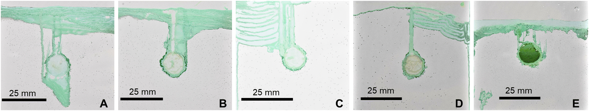 | ||
| Fig. 2 Labyrinth experiment ∼20 hours after the start of the reaction, using a copper chloride (CuCl2) pill inside a Hele-Shaw cell and submerged in (A) 1 M, (B) 2 M, (C) 3 M, (D) 4 M, and (E) 5 M sodium silicate solution. | ||
Copper chloride [CuCl2] labyrinths
In experiments with CuCl2 we observed that different structures formed for each sodium silicate concentration tested (Fig. 2a–e). 1 M (Fig. 2a) and 2 M (Fig. 2b) silicate experiments exhibited vertical precipitate tubes growing upwards and precipitation of a “roof” (Stages 1 and 2). The width of the labyrinth tube in Stage 1 was determined by the bubble size; however, during Stage 3 (reached at 3 M silicate) the growth followed a laminar pattern with layer separation of ∼0.2 mm (Fig. 2C). Well-defined labyrinths were only observed in 3 M (Fig. 2c) and 4 M (Fig. 2d) silicate experiments. The thickness of the tubes forming the labyrinth varied from 0.8 mm to 1.5 mm for 3 M and from 1 mm to 2.5 mm for 4 M silicate. At 5 M silicate (Fig. 2e), no labyrinths formed, but thinner bubble-guided tubes were observed growing downwards or upwards.Copper nitrate [Cu(NO3)2] labyrinths
Similar to the CuCl2 experiments, different concentrations of silicate led to formation of different structures with Cu(NO3)2 (Fig. 3). At 1 M silicate (Fig. 3a), all bubbles separated from the pill before forming the initial thick tube (contrary to what we have seen in CuCl2 at 1M), and so the precipitate could not complete Stage 2 (roof growth). With 2 M (Fig. 3b) and 3 M silicate (Fig. 3c) experiments showed similar structures to those obtained with CuCl2: some bubbles were created after filling the cell with the silicate and bubble-guided growth of the initial tube occurred. Afterwards, however, it did not create a periodic labyrinth structure; instead, most of the material formed a laminar structure with small layer separation (∼0.2 mm). On the other hand, with 4 M (Fig. 3d) and 5 M (Fig. 3e) silicate we observed formation of much more defined and periodic labyrinths. | ||
| Fig. 3 Labyrinth experiment ∼20 hours after the start of the reaction, using a copper nitrate (Cu(NO3)2) pill inside a Hele-Shaw cell and submerged in (A) 1 M, (B) 2 M, (C) 3 M, (D) 4 M, and (E) 5 M sodium silicate solution. | ||
Because the width of the tube is controlled by the size of the initial bubble, this width could be reproduced by controlling the bubble. Knowing these variables, we could also decide the approximate length of the tubes, which also depends on the mass of the pill and its distance of the cell roof and sides. On the other hand, the windings and of the labyrinth and the new precipitates are not completely reproducible at the moment, except if we control the growth.
Quantifying the effect of silicate concentration on labyrinths growth with Cu salts
There were similarities between the evolution of the labyrinths depending on silicate concentration for both Cu salts. Both had a range of silicate concentrations where labyrinths were stable, with wider, periodic channels (3 M and 4 M silicate for CuCl2, and 4 M and 5 M silicate for Cu(NO3)2). There was also a silicate concentration range for each in which the precipitate created a layered laminar pattern instead of the usual wider canals (1 M and 2 M silicate for CuCl2, and 2 M and 3 M silicate for Cu(NO3)2). In the case of CuCl2 at 5 M silicate, the precipitate reverted back to this laminar pattern (Fig. 2e).For CuCl2, the labyrinth channel widths increased with time (due to the pressure of the internal fluid) (Fig. 4A); the lower silicate concentration (3 M) created wider channels. The labyrinths obtained with 3 M and 4 M silicate and CuCl2 grew slowly, with velocities on the order of 10−3 mm s−1, with velocity decreasing exponentially over time (Fig. 4B). This may be the result of the mass of the pill decreasing as it dissolved, thus decreasing the internal fluid pressure that pushes the bubble up. The growth rate of the rest of the CuCl2 experiments that show only laminar growth (1 M, 2 M, and 5 M silicate) (Fig. 4C) all show a similar tendency, where the rate of growth diminishes over time until the labyrinth becomes static. This agrees with what we expected: the pressure from the material in the pill decreases as said material transforms into the labyrinth or laminar precipitate, finally stopping the growth when the pill is completely dissolved. However, CuCl2 experiments at different silicate concentrations vary in their area growth over time, with less concentration causing a more rapid growth than higher ones. Also, note that these curves do not start at the zero origin because there were already some black pixels before filming; that is the pill as well as the borders of the Hele-Shaw cell.
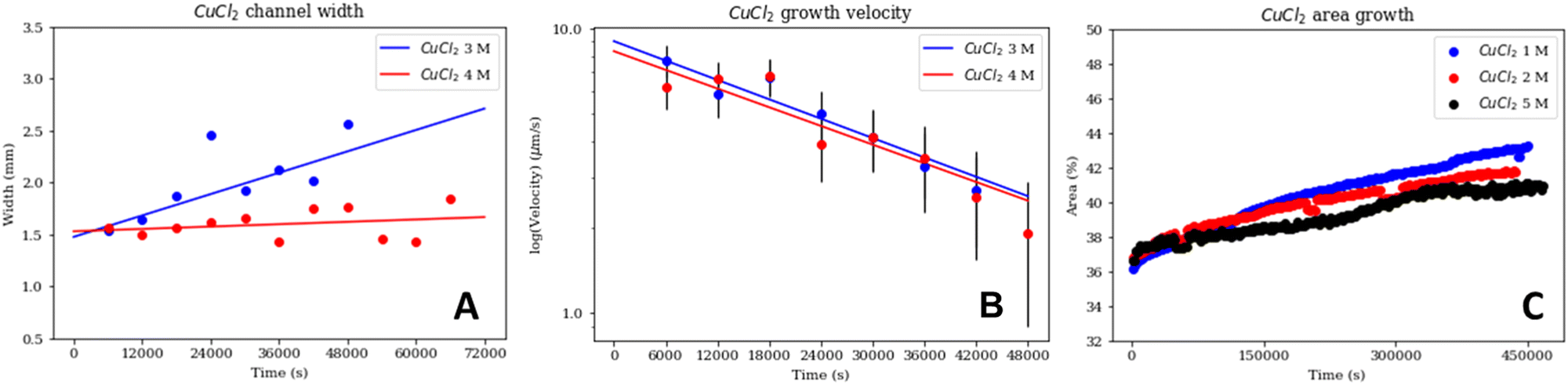 | ||
| Fig. 4 Graphical representation of the evolution of the (A) 2D tube or channel width and (B) tube growth velocity of the CuCl2 + 3 M (blue) and 4 M (red) sodium silicate labyrinths during the first ∼20 hours with an error of 1 μm; as well as of the (C) rate of growth of the labyrinth through the percentage of the cell area covered by the CuCl2 + 1 M (blue), 2 M (red), and 5 M (black) sodium silicate chemical gardens. The coefficients of determination for the fit lines in (A) are R2 = 0.567 (blue) and R2 = 0.693 (red), and in (B) R2 = 0.923 (blue) and R2 = 0.869 (red). The error in the width in 4a is approximately 3%, not great enough to be represented. Note that the lines in 4c do not start at 0% because they represent the area in the cell with material, which could include the initial pill and the cell borders. | ||
For Cu(NO3)2, the behaviour of the tube widths for 4 M and 5 M silicate also increased with time (Fig. 5A); however, in this case the 5 M experiment had wider channels than the 4 M experiment, contrary to Fig. 4B. The growth velocities of the labyrinths in the 4 M and 5 M silicate Cu(NO3)2 experiments followed a similar exponentially decreasing tendency, and again in this case the higher concentration experiment (5 M silicate) was slower (Fig. 5B). However, the initial velocities for Cu(NO3)2 were much higher than for CuCl2. Finally, for the silicate concentrations that created laminar structures with Cu(NO3)2 (2 M, and 3 M); we can see that the garden growth rate decreases and tends to become constant (Fig. 5C). There was a bigger difference between the growth curves for the Cu(NO3)2 experiments than for the CuCl2; and in the case of Cu(NO3)2 the higher silicate concentration (3 M) led to faster growth.
 | ||
| Fig. 5 Graphical representation of the evolution of the (A) tube width and (B) tube growth velocity of the Cu(NO3)2 + 4 M (red) and 5 M (blue) sodium silicate labyrinths during the first ∼10 hours with an error of 1 μm; as well as of the (C) rate of growth of the labyrinth through the percentage of the cell area covered by the Cu(NO3)2 + 2 M (red), and 3 M (blue) sodium silicate chemical gardens. The coefficients of determination for the fit lines in (a) are R2 = 0.819 (red) and R2 = 0.795 (blue), and in (b) R2 = 0.812 (red) and R2 = 0.891 (blue). The error in the width in 5a is approximately 3%, not great enough to be represented. Note that the lines in 5c do not start at 0% because they represent the area in the cell with material, which could include the initial pill and the cell borders. | ||
Chemical microanalysis
We conduced further chemical microanalysis on two samples of precipitate from Cu salt experiments that produced the most well-defined labyrinths (3 M silicate + CuCl2, and 5 M silicate + Cu(NO3)2).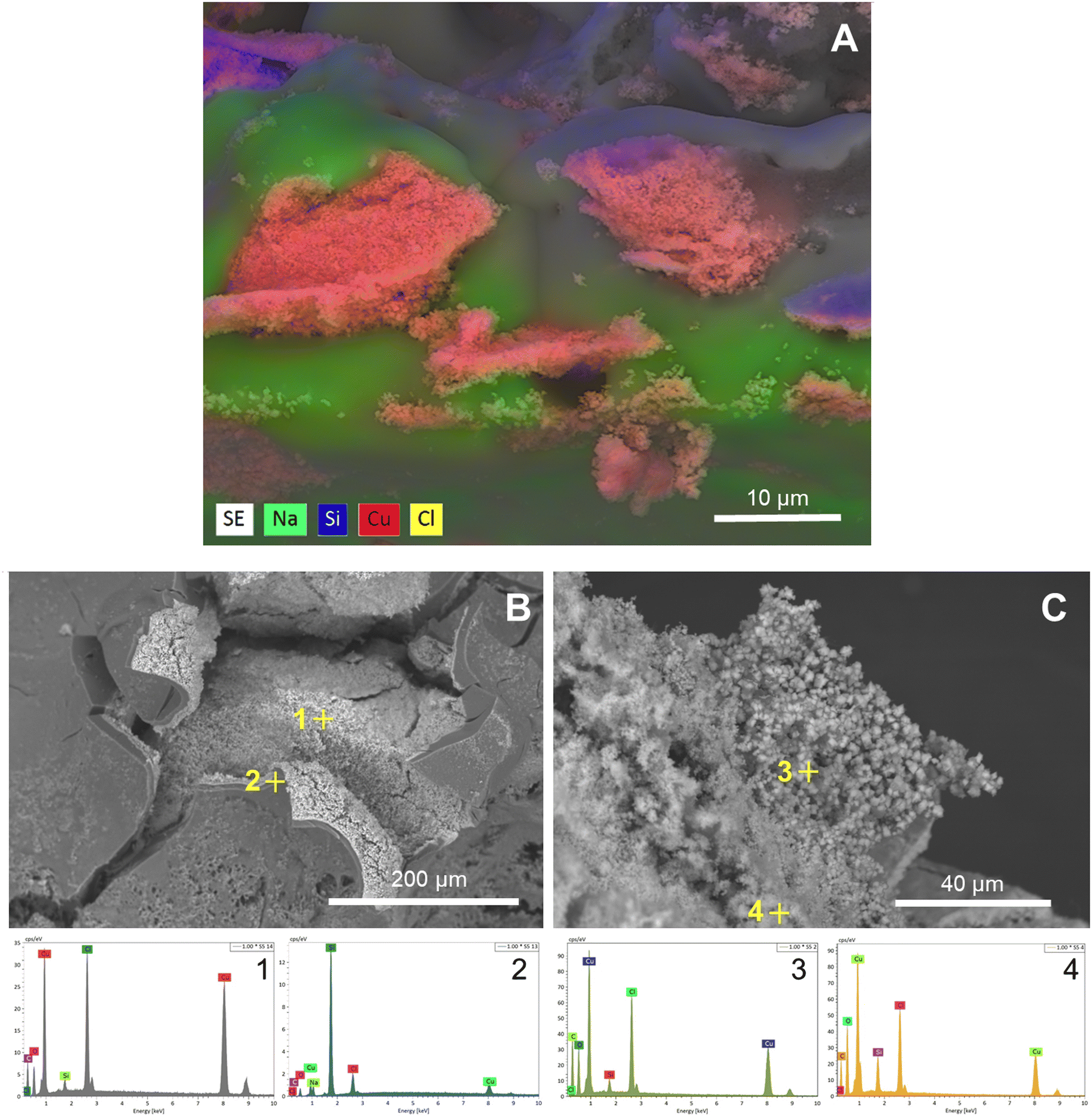 | ||
| Fig. 6 (A) EDX elemental analysis map of a CuCl2 3 M silicate labyrinth showing Na, Si, Cu, and Cl. (B) SEM of the peeled-off Si-layer of a CuCl2 3 M silicate labyrinth with EDX analysis of interior and exterior. (C) SEM of the crystals formed inside of a CuCl2 3 M silicate labyrinth with EDX analysis of the crystals. | ||
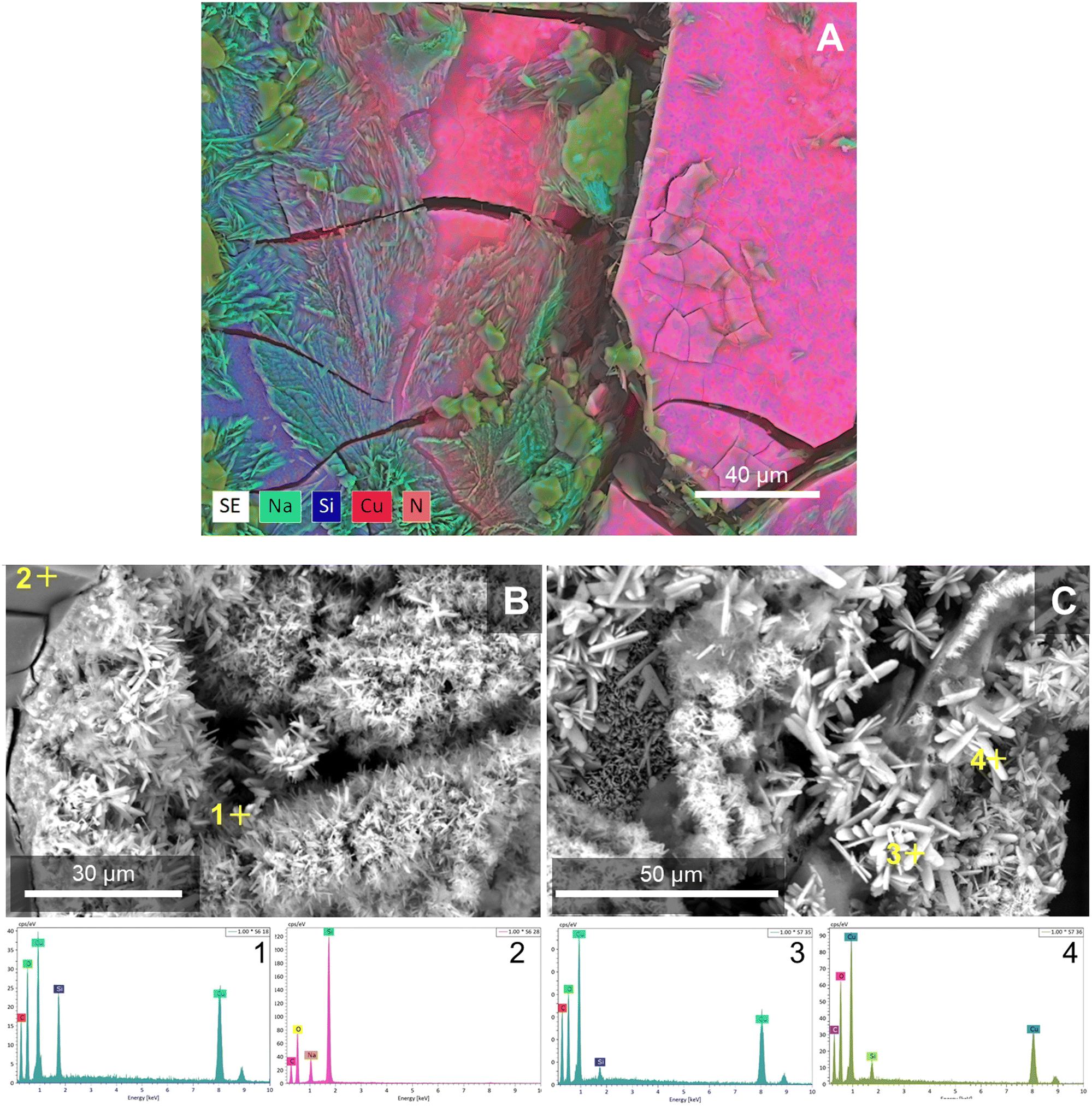 | ||
| Fig. 7 (A) EDX elemental analysis map of a Cu(NO3)2 5 M silicate sample showing Na, Si, Cu, and N on the precipitate surface. (B) SEM of the broken surface of a Cu(NO3)2 5 M silicate labyrinth with EDX analysis of interior and exterior. (C) SEM and EDX of the crystals formed inside of a Cu(NO3)2 5 M silicate labyrinth. | ||
 | ||
| Fig. 8 (a) and (b) XRD patterns of (a) CuCl2 3 M silicate labyrinth sample P are paratacamite peaks and H are halite peaks, and (b) Cu(NO3)2 + 5 M silicate labyrinth sample where R are rouaite -peaks. (c) and (d) Micro-Raman analysis spectra of (c) CuCl2 + 3 M silicate labyrinth sample, and (d) Cu(NO3)2 + 5 M silicate labyrinth sample. P are paracatamite peaks, H are halite peaks, and R are rouaite peaks. | ||
 | ||
| Fig. 9 Labyrinth experiment using a Cu(NO3)2 pill inside a Hele-Shaw cell and submerged in a 5 M sodium silicate solution (A) ∼20 minutes after the start of the reaction rotated 45° to the left; (B) ∼40 minutes after the start of the reaction rotated 45° to the right; and (C) its finished structure after ∼20 hours. The bubble guides the tube to the top of the cell even with the experiment rotated. | ||
Controlling the labyrinth
In an experiment with 5 M silicate + Cu(NO3)2, when the cell was rotated 45° to the left at the start of the experiment, the initial bubble-guided tube grew vertically upward (perpendicular to the ground) (Fig. 9a) rather than parallel to the cell walls as in previous experiments. Moreover, after changing the rotation to 45° to the right, the tube changed direction to similarly grow perpendicular to the ground (Fig. 9b). This is expected since bubble-guided tube growth is buoyancy directed and therefore changing the orientation of the cell relative to gravity will allow the ability to direct the direction of tube growth as long as a bubble is present. As we can see in Fig. 9c, after some time the final labyrinth also stayed parallel to the ground instead of following the rotation of the cell. Although this is a simple test, it was enough to affirm that the labyrinth's geometry can be changed at will through external modifications. For example, changing the direction of the cell so that the labyrinth is always growing downwards may increase the velocity of its growth.Conclusions
Our experiments studying of the formation of chemical gardens in 2D reactors uncovered a curious phenomenon: the formation of labyrinthine structures. The conditions for this formation are a balance of concentration of the silicate solution and the type of Cu salt of the seed used. One necessary condition needed for this phenomenon is the existence of a gas bubble. The balance between the buoyancy forces of this gas bubble and the osmotic pressure of the internal solution, along with the mechanical properties of the precipitate that forms the labyrinth walls, allows the formation of these structures. One property that varies between the Cu salts is their solubility. Lower solubilities can decrease the reactivity of the pellet or increase the mechanical resistance to the bubble movement. The Cu salts used have high solubility allowing the formation of these labyrinths. However, solubility cannot be too high, as then a higher concentration of silicate would be needed to reach the balance necessary for the labyrinth formation (as seen with the highly soluble Cu(NO3)2).Even though the labyrinths in this study were based on only two Cu metal salts (CuCl2 and Cu(NO3)2), chemical gardens can be formed with a wide variety of metal salt seed crystals,19 and so it would be worthwhile to explore which other chemistries could also produce labyrinth structures. As commented previously, the formation of labyrinths (as opposed to laminar precipitates) in other chemistries would be dependent upon the details of the system including the metal salt cation and anion, and silicate concentration. The growth stages we present for these 2D chemical garden systems are generally useful since for any metal salt plus silicate chemistry that is able to reach stage 3 (labyrinth growth from bubble-guided tube formation), it would be theoretically possible to control the geometry of the labyrinth by rotating the experiment as shown in Fig. 9. The walls of the two labyrinth structures studied here exhibited crystals related to the metal salt coating the inner walls and silicate on the exterior, as has been observed in previous chemical garden studies. Chemical garden systems such as these serve as an interesting example of inorganic self-organization, and could be used to create microfluidic labyrinths which could facilitate reactivity on the interior crystalline walls, the composition and orientation of which could be externally controlled.
Author contributions
S.T.M., T.H.M., and P.K. conducted the lab experiments. J.H.E.C. and C.I.S.D. developed the 2D reactor technique. S.T.M. and C.I.S.D. conducted microscopy analysis. S.T.M., L.M.B., C.I.S.D., and J.H.E.C. wrote the paper.Conflicts of interest
There are no conflicts to declare.Acknowledgements
L. M. B. was supported by JPL Topical Research & Technology Development and a NASA PECASE award; L. M. B's research was carried out at the Jet Propulsion Laboratory, California Institute of Technology, under a contract with the National Aeronautics and Space Administration (80NM0018D0004). S. T. and T. H. thank the CSIC and Spanish Andalusian ‘Garantía Juvenil’ project AND21_IACT_M2_058. The authors would like to acknowledge the contributions of the European COST Action CA17120 supported by the EU Framework Programme Horizon 2020.Notes and references
- J. Kingsley, The Art Book, 2010, 17, 90–92 CrossRef.
- K. Suzuno, D. Ueyama and I. Lagzi, Curr. Phys. Chem., 2015, 5, 29 CrossRef CAS.
- A. Adamatzky, Shortest Path Solvers. From Software to Wetware, Springer, 2018, pp. 421–438 Search PubMed.
- O. Steinbock, Á. Tóth and K. Showalter, Science, 1995, 267, 868 CrossRef CAS PubMed.
- I. Lagzi, S. Soh, P. J. Wesson, K. P. Browne and B. A. Grzybowski, J. Am. Chem. Soc., 2010, 132, 1198 CrossRef CAS PubMed.
- A. Reynolds, Phys. Rev. E, 2010, 81, 062901 CrossRef CAS PubMed.
- K. Suzuno, D. Ueyama, M. Branicki, R. Tóth, A. Braun and I. Lagzi, Langmuir, 2014, 30, 9251 CrossRef CAS PubMed.
- A. Adamatzky, A. Chiolerio and K. Szaciłowski, Soft Matter, 2020, 16, 1455 RSC.
- G. Zhao and M. Pumera, Lab Chip, 2014, 14, 2818 RSC.
- J. Qin and A. R. Wheeler, Lab Chip, 2007, 7, 186 RSC.
- B. Sandnes, H. Knudsen, K. Måløy and E. Flekkøy, Phys. Rev. Lett., 2007, 99, 038001 CrossRef CAS PubMed.
- S. Kobayashi, et al. , Appl. Phys. Lett., 2013, 102, 231911 CrossRef.
- H. J. Bae, S. Bae, J. Yoon, C. Park, K. Kim, S. Kwon and W. Park, Sci. Adv., 2017, 3, e1700071 CrossRef PubMed.
- J. Dickstein, S. Erramilli, R. E. Goldstein, D. P. Jackson and S. A. Langer, Science, 1993, 261, 1012 CrossRef PubMed.
- D. Walker, P. K. Verma, L. M. D. Cranswick, R. L. Jones, S. M. Clark and S. Buhre, Am. Mineral., 2004, 89, 204–210 CrossRef CAS.
- S. Chu, P. Müller, D. G. Nocera and Y. S. Lee, Appl. Phys. Lett., 2011, 98, 092508 CrossRef.
- H. Effenberger, Z. Kristallogr., 1983, 165, 127–135 CrossRef CAS.
- L. Kong, X. Chen, G. Yang, L. Yu and P. Zhang, Appl. Surf. Sci., 2008, 254, 7255–7258 CrossRef CAS.
- R. L. Frost, W. Martens, J. T. Kloprogge and P. A. Williams, J. Raman Spectrosc., 2002, 33, 801–806 CrossRef CAS.
- L. M. Barge, et al. , Chem. Rev., 2015, 115(16), 8652–8703 CrossRef CAS PubMed.
- S. Thouvenel-Romans, J. J. Pagano and O. Steinbock, Phys. Chem. Chem. Phys., 2005, 7, 2610–2615 RSC.
- F. Haudin, J. H. E. Cartwright, F. Brau and A. De Wit, PNAS, 2014, 111(49), 17363–17367 CrossRef CAS PubMed.
- M. Copisarow, J. Chem. Soc., 1927, 222–234 RSC.
- G. J. T. Cooper and L. Cronin, J. Am. Chem. Soc., 2019, 131, 8368–8369 CrossRef PubMed.
- G. J. T. Cooper, R. W. Bowman, E. P. Magennis, F. Fernandez-Trillo, C. Alexander, M. J. Padgett and L. Cronin, Angew. Chem., 2012, 51, 12754–12758 CrossRef CAS PubMed.
- S. Hussein, J. Maselko and J. T. Pantaleone, Langmuir, 2016, 32(3), 706–711 CrossRef CAS PubMed.
- M. R. Bentley, B. C. Batista and O. Steinbock, J. Phys. Chem., 2016, 120(25), 4294–4301 CrossRef CAS PubMed.
Footnote |
| † Electronic supplementary information (ESI) available. See DOI: https://doi.org/10.1039/d3cp02929h |
| This journal is © the Owner Societies 2023 |