 Open Access Article
Creative Commons Attribution 3.0 Unported Licence
Preparation of carbon–sulphur composite electrodes by solution impregnation and application to all-solid-state lithium–sulphur batteries
Sakura
Niwa
a,
Yuta
Fujii
 *b,
Nataly Carolina
Rosero-Navarro
 bc,
Akira
Miura
 b,
Kiyoharu
Tadanaga
 b,
Riku
Maniwa
 d,
Misaki
Fujimoto
d,
Harumi
Takada
d and
Masahiro
Morooka
d
d,
Misaki
Fujimoto
d,
Harumi
Takada
d and
Masahiro
Morooka
d
aGraduate School of Chemical Sciences and Engineering, Hokkaido University, Kita-ku, Sapporo, Hokkaido 060-8628, Japan
bFaculty of Engineering, Hokkaido University, Kita-ku, Sapporo, Hokkaido 060-8628, Japan. E-mail: fujii.yuta@eng.hokudai.ac.jp
cInstitute of Ceramics and Glasses, CSIC, Madrid, Spain
dNissan Motor Co., Ltd, Natsushima, Yokosuka, Kanagawa 237-8523, Japan
First published on 29th January 2024
Abstract
All-solid-state lithium–sulphur batteries have attracted attention because of their high theoretical capacity and suppression of polysulphide dissolution in organic liquid electrolytes. In this study, sulphur–carbon composites were prepared by impregnating sulphur and a solid electrolyte into the pores of carbon particles using the liquid phase. First, sulphur was impregnated into porous carbon using sulphur-dissolved in toluene and the solvent was subsequently removed. Then, sulphur–carbon composites with and without heat treatment at 155 °C were prepared. Solid electrolyte (SE, Li6PS5Cl) was impregnated into the sulphur–carbon composites using an ethanol solution of Li6PS5Cl. All-solid-state lithium–sulphur batteries were fabricated using the solid electrolyte–sulphur–carbon composites and Li2S–P2S5 solid electrolyte. The batteries showed almost the same capacity despite heating and not heating at 155 °C after sulphur solution impregnation.
Introduction
Lithium-ion secondary batteries have been widely used as power sources because of their high energy density and good cycling ability.1–4 However, the development of lithium-ion secondary batteries with higher energy density is still required, especially for application in electronic vehicles. Elemental sulphur has attracted much attention as a cathode material because of its large theoretical capacity (1672 mA h g−1), and low cost.5–7 However, lithium–sulphur (Li–S) batteries have some problems, such as (1) the rapid capacity fading due to the dissolution of lithium polysulphide (Li2Sn) species as the intermediate product into organic liquid electrolytes, (2) low electron conductivity of both elemental sulphur and lithium sulphide and (3) large volume change between sulphur and lithium sulphide (approximately 80%) during cycling. These problems are still preventing commercial and practical applications.One of the critical issues is the formation of the conduction paths in the cathode. In Li–S batteries using organic liquid electrolytes, the embedding of sulphur into the pores of conductive additive carbon has been investigated.8,9 This hybridization of sulphur and carbon is expected to form an electron conduction path in the cathode and suppress the dissolution of polysulphide species into liquid electrolytes. The melt-diffusion process, in which sulphur is impregnated into carbon by pre-mixing sulphur and carbon and subsequent heat treatment at a temperature slightly above the melting point of sulphur (155 °C), is widely used to prepare sulphur–carbon composites. Because elemental sulphur can dissolve in some organic solvents such as toluene and CS2, sulphur can also be embedded in carbon pores by impregnating a sulphur solution.10–14 Some researchers have reported the combination of solution impregnation and subsequent melt-diffusion.11–13 This process has the potential to uniformly distribute sulphur in fine carbon particles of several micrometres to tens of micrometres in size. In this process, carbon is mixed with a solution of sulphur, the solvent is removed by evaporation, and then the sulphur with carbon is heated to sulphur-impregnation by melting into carbon. It is also expected that the use of porous carbon as a conductive additive can buffer the large volume change of sulphur.
On the other hand, all-solid-state Li–S batteries using a solid electrolyte instead of an organic liquid electrolyte can prevent the dissolution of lithium polysulphide species into liquid electrolytes.15–17 Furthermore, all-solid-state Li–S batteries using flame-retardant solid electrolytes are expected to improve safety issues.6 Sulphide-based solid electrolytes have been reported to have high ionic conductivities close to those of liquid electrolytes.18,19 In addition, they can be densified by cold pressing.20 Because of these characteristics, sulphide-based solid electrolytes are advantageous for all-solid-state batteries in which the starting materials are a powder.
In all-solid-state Li–S batteries, contact between the sulphur in the carbon pores and the solid electrolyte is difficult because the electrolyte does not penetrate, unlike liquid electrolyte.21,22 In order to form a favourable contact between the sulphur and solid electrolyte, the liquid phase synthesis of the solid electrolyte can be used. Our group has reported the synthesis of sulphide-based solid electrolytes in the liquid phase.23–25 There are mainly two processes for liquid-phase synthesis. The first one is the suspension process, in which the raw materials, such as Li2S and P2S5, are dispersed in a solvent to form a suspension. The other one is the dissolution–precipitation process, in which a solid electrolyte is dissolved in a solvent to form a uniform solution, and then the solvent is removed to deposit the solid electrolyte. Liquid-phase synthesis has the advantage of easy scale-up and expected particle size control. Solid electrolyte solutions are also suitable for generating thin solid electrolyte layers by removing the solvent. Our group reported coating the active material with a solid electrolyte.26,27 The study using Li(Ni, Mn, Co)O2 (NMC) as the active material showed that coating the solid electrolyte with NMC increased the capacity. The study using graphite as the active material also revealed that the battery using graphite coated with solid electrolyte showed excellent rate performance.
In this study, composites for all-solid-state Li–S batteries were prepared by impregnating both sulphur and solid electrolyte in the liquid phase within porous carbon particles. First, the composites of sulphur and carbon were prepared by impregnating sulphur in porous carbon using a solution of sulphur dissolved in toluene. The effect of melt-diffusion by heat treatment at 155 °C after solution impregnation was investigated. Then, the solid electrolyte–sulphur–carbon composites were prepared by impregnating a small quantity of a solid electrolyte into the sulphur–carbon composite by using a liquid phase process. By the liquid phase process, lithium-ion paths are expected to be formed in the pores, leading to the high performance of the batteries. Finally, the composite cathodes were prepared by using these solid electrolyte–sulphur–carbon composites, and their performance in all-solid-state Li–S batteries was evaluated.
Experimental
Sulphur–carbon composites (S–C) were prepared using toluene (Wako chemical, super hydrated) as a solvent to dissolve sulphur. Elemental sulphur (0.6 g) was added to toluene (10 mL) and dissolved by magnetic stirring at 90 °C (Fig. 1a). Porous carbon (0.12 g) with a specific surface area of approximately 1300 m2 g−1 and a pore volume of approximately 3.0 cm3 g−1 was added to this sulphur solution, and then the solution was stirred and dried at 90 °C. The carbon was used without any treatment before the addition process into the sulphur solution. The sample (S–C_H.T.) was prepared by heating S–C at 155 °C for 12 hours. The weight ratio of sulphur to carbon in the prepared composites was 5![[thin space (1/6-em)]](https://www.rsc.org/images/entities/char_2009.gif) :
:![[thin space (1/6-em)]](https://www.rsc.org/images/entities/char_2009.gif) 1.
1.
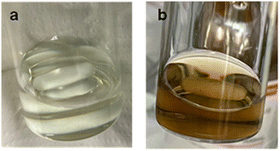 | ||
| Fig. 1 The image of the (a) sulphur solution using toluene and (b) solid electrolyte (Li6PS5Cl) solution using ethanol. | ||
Li6PS5Cl, soluble in ethanol, was selected as a solid electrolyte impregnated in the sulphur–carbon composites (S–C/S–C_H.T.). Li6PS5Cl (0.03 g) was dissolved in ethanol (3 mL) (Fig. 1b). The samples, SE–S–C/SE–S–C_H.T., were prepared by adding S–C/S–C_H.T. to this Li6PS5Cl solution, and the solution was dried at 80 °C. The samples, SE–S–C/SE–S–C_H.T., were prepared in the following weight ratio: solid electrolyte (Li6PS5Cl)![[thin space (1/6-em)]](https://www.rsc.org/images/entities/char_2009.gif) :
:![[thin space (1/6-em)]](https://www.rsc.org/images/entities/char_2009.gif) sulphur
sulphur![[thin space (1/6-em)]](https://www.rsc.org/images/entities/char_2009.gif) :
:![[thin space (1/6-em)]](https://www.rsc.org/images/entities/char_2009.gif) carbon = 0.5
carbon = 0.5![[thin space (1/6-em)]](https://www.rsc.org/images/entities/char_2009.gif) :
:![[thin space (1/6-em)]](https://www.rsc.org/images/entities/char_2009.gif) 5
5![[thin space (1/6-em)]](https://www.rsc.org/images/entities/char_2009.gif) :
:![[thin space (1/6-em)]](https://www.rsc.org/images/entities/char_2009.gif) 1. Here, Li6PS5Cl (1.2 × 10⁻³ S cm−1) was synthesized by mechanical milling of Li2S (Mitsuwa Chemical, 99.9%), P2S5 (Aldrich, 99%), and LiCl (Aldrich, 99.95%). Li2S, P2S5, and LiCl were mixed using an agate mortar. The mixture was mechanically milled using a planetary ball mill (Fritsch, Pulverisette 7) with a zirconia pot (45 mL volume) and 10 zirconia balls (ϕ = 10 mm) in a dry Ar atmosphere at 600 rpm for 40 hours.
1. Here, Li6PS5Cl (1.2 × 10⁻³ S cm−1) was synthesized by mechanical milling of Li2S (Mitsuwa Chemical, 99.9%), P2S5 (Aldrich, 99%), and LiCl (Aldrich, 99.95%). Li2S, P2S5, and LiCl were mixed using an agate mortar. The mixture was mechanically milled using a planetary ball mill (Fritsch, Pulverisette 7) with a zirconia pot (45 mL volume) and 10 zirconia balls (ϕ = 10 mm) in a dry Ar atmosphere at 600 rpm for 40 hours.
The X-ray diffraction (XRD) patterns of the prepared samples were measured using an X-ray diffractometer (Miniflex 600, Rigaku) under Cu-Kα radiation. In the measurement of the samples containing air-sensitive materials such as SE–S–C, SE–S–C_H.T., or Li6PS5Cl, a sample stage covered with Kapton film to avoid undesired reaction of the samples with air was used. Nitrogen adsorption/desorption isotherms were obtained by using a Microtrac BEL (Belsorp mini II, Microtrac Corp.) at liquid N2 temperature. The specific surface area and pore size distribution of carbon, S–C, and S–C_H.T. were estimated using the Brunauer–Emmett–Teller (BET) and Barrett–Joyner–Halenda (BJH) methods, respectively. The morphology and elemental mapping were studied using a scanning electron microscope (SEM; TM3030Plus Miniscope, HITACHI) and focused ion beam-scanning electron microscopy (FIB-SEM; JIB-4600, JEOL) in conjunction with an energy dispersive spectroscopy (EDS) system. The sulphur contents of S–C and S–C_H.T. were determined by thermogravimetry (TG-DTA; STA 300, HITACHI) run to 500 °C at the rate of 10 °C min−1 under Ar flow.
The sulphur composite cathodes for all-solid-state Li–S batteries were prepared by mixing SE–S–C/SE–S–C_H.T. with additional solid electrolyte, 60Li2S·40P2S5 (mol%) glass (3.2 × 10⁻⁶ S cm−1).28 The weight ratio of SE–S–C/SE–S–C_H.T. and 60Li2S·40P2S5 was set to 65![[thin space (1/6-em)]](https://www.rsc.org/images/entities/char_2009.gif) :
:![[thin space (1/6-em)]](https://www.rsc.org/images/entities/char_2009.gif) 35, so that SE (Li6PS5Cl + 60Li2S·40P2S5)
35, so that SE (Li6PS5Cl + 60Li2S·40P2S5)![[thin space (1/6-em)]](https://www.rsc.org/images/entities/char_2009.gif) :
:![[thin space (1/6-em)]](https://www.rsc.org/images/entities/char_2009.gif) S
S![[thin space (1/6-em)]](https://www.rsc.org/images/entities/char_2009.gif) :
:![[thin space (1/6-em)]](https://www.rsc.org/images/entities/char_2009.gif) C = 40
C = 40![[thin space (1/6-em)]](https://www.rsc.org/images/entities/char_2009.gif) :
:![[thin space (1/6-em)]](https://www.rsc.org/images/entities/char_2009.gif) 50
50![[thin space (1/6-em)]](https://www.rsc.org/images/entities/char_2009.gif) :
:![[thin space (1/6-em)]](https://www.rsc.org/images/entities/char_2009.gif) 10 (wt%) in the prepared sulphur composite cathodes. SE–S–C/SE–S–C_H.T. and 60Li2S·40P2S5 (total 0.4 g) were hand-mixed in an agate mortar and then mechanically milled using a planetary ball mill with a zirconia pot (45 mL volume) and zirconia balls (ϕ = 5 mm, 40 g) in a dry Ar atmosphere at 370 rpm for 15 min. This mechanical milling process was performed eight times with one-minute intervals.
10 (wt%) in the prepared sulphur composite cathodes. SE–S–C/SE–S–C_H.T. and 60Li2S·40P2S5 (total 0.4 g) were hand-mixed in an agate mortar and then mechanically milled using a planetary ball mill with a zirconia pot (45 mL volume) and zirconia balls (ϕ = 5 mm, 40 g) in a dry Ar atmosphere at 370 rpm for 15 min. This mechanical milling process was performed eight times with one-minute intervals.
75Li2S·25P2S5 (mol%) glass, which has higher ion conductivity than 60Li2S·40P2S5 (mol%), was employed as the separator of the all-solid-state battery. All-solid-state Li–S batteries were fabricated in the following process. Sulphur composite electrodes (10 mg) and the 75Li2S·25P2S5 glass solid electrolyte (2.2 × 10⁻⁴ S cm−1, 120 mg) were placed into a polycarbonate tube (ϕ = 10 mm) and pressed under 360 MPa. A Li–In alloy foil was attached to the bilayer pellet consisting of the sulphur composite electrode and the solid electrolyte layers by uniaxially pressing them together at 120 MPa. These pellets were sandwiched by two stainless-steel disks as current collectors. The assembled all-solid-state Li–S batteries were discharged and charged under constant current constant voltage (CCCV) mode using a discharge–charge measuring device (Scribner Associates, 580 battery-type system). The discharge–charge measurement was initiated with discharge. The cut-off voltage was set to 0.5 V vs. Li–In for discharging and 2.5 V vs. Li–In for charging.
Results and discussion
Fig. 2 shows the XRD patterns of the prepared S–C and S–C_H.T. The XRD pattern of the raw material sulphur is also shown for comparison. In the S–C sample, the peaks attributed to α-S8 corresponding to the raw material were mainly observed. On the other hand, the peaks due to β-S8 and a halo pattern, which can be the amorphous sulphur inside the carbon nanopores, were confirmed in S–C_H.T. These results indicated that sulphur melted by heating at 155 °C and a part of the sulphur impregnated in the carbon pores in S–C_H.T.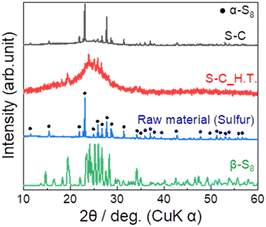 | ||
| Fig. 2 The XRD patterns of the prepared S–C and S–C_H.T. For comparison, the XRD patterns of the raw material α-sulphur (black circles ●) and β-sulphur are also shown. | ||
Fig. 3a shows the N2 adsorption/desorption isotherms of the prepared S–C and S–C_H.T. Fig. 3b exhibits the enlarged figure. The isotherms of the raw material carbon before sulphur impregnation are also shown in Fig. 3a for comparison. The enlarged N2 adsorption/desorption isotherms for S–C and S–C_H.T. are shown on the bottom. The specific surface area of the raw material, S–C and S–C_H.T. was determined to be 1.3 × 10³ m2 g−1, 11 m2 g−1, and 7.6 m2 g−1, respectively. The specific surface area was significantly decreased by sulphur impregnation to carbon. In addition, the specific surface area of S–C_H.T. prepared by melt-diffusion at 155 °C after solution impregnation is only slightly smaller than that of S–C, indicating that melt-diffusion leads to a slight decrease in the specific surface area. These results suggest that sulphur can fill most of the entrances of the carbon pores by solution impregnation alone without the melt-diffusion process.
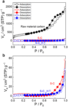 | ||
| Fig. 3 (a) The N2 adsorption/desorption isotherms of the raw material carbon, S–C and S–C_H.T. (b) The enlarged N2 adsorption/desorption isotherms are also shown. | ||
Fig. 4a–c shows the SEM images of the raw material carbon, S–C, and S–C_H.T. The morphologies of S–C and S–C_H.T. are almost the same as the raw material. The results of N2 adsorption/desorption isotherms and SEM images suggest that sulphur particles were embedded within the carbon pores in S–C and S–C_H.T. by using a solution of sulphur.
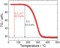
Fig. 5 shows the TG profiles of S–C and S–C_H.T. In both samples, the abrupt weight loss attributed to the sublimation of sulphur between 170 °C and 350 °C was confirmed, and the weight loss of S–C and S–C_H.T. was 83.2 wt% and 82.3 wt%, respectively. Because the S–C and S–C_H.T. samples were prepared with sulphur![[thin space (1/6-em)]](https://www.rsc.org/images/entities/char_2009.gif) :
:![[thin space (1/6-em)]](https://www.rsc.org/images/entities/char_2009.gif) carbon = 5
carbon = 5![[thin space (1/6-em)]](https://www.rsc.org/images/entities/char_2009.gif) :
:![[thin space (1/6-em)]](https://www.rsc.org/images/entities/char_2009.gif) 1 (wt ratio), the theoretical weight of sulphur in these composites is 83.3 wt%. The calculated weight loss of sulphur in both S–C and S–C_H.T. is close to this value, although the sulphur content is slightly reduced.
1 (wt ratio), the theoretical weight of sulphur in these composites is 83.3 wt%. The calculated weight loss of sulphur in both S–C and S–C_H.T. is close to this value, although the sulphur content is slightly reduced.
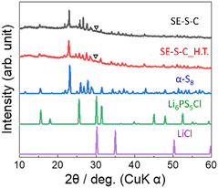
Fig. 6 shows the XRD patterns of the prepared SE–S–C and SE–S–C_H.T. In both samples, the peaks were mainly attributed to α-S8. While the peaks of S–C_H.T. were attributed to β-S8, the peaks of SE–S–C_H.T. after the solid electrolyte impregnation were mainly attributed to α-S8. These different XRD patterns suggest that the metastable phase β-S8 transformed into the stable phase α-S8 during the process of solid electrolyte impregnation. In addition, there is also a small peak at around 30°, which could be attributed to the strongest peak of Li6PS5Cl or LiCl.
Fig. 7a–e show the SEM image and EDS mapping of S, C, Cl, and P of SE–S–C, respectively. Cl and P were distributed throughout. These results confirmed that the solid electrolyte was uniformly impregnated. On the other hand, there are some points where only the Cl mapping is bright, indicating that small particles containing Cl are present in addition to the impregnated solid electrolyte Li6PS5Cl. This suggests that Li6PS5Cl synthesized by mechanical milling was partially precipitated as LiCl when it was reprecipitated with ethanol. Despite this phenomenon, the lithium-ion conductivity of the reprecipitated Li6PS5Cl has been reported to be maintained on the order of 10−5 S cm−1,26 which is expected to not significantly affect the battery performance.
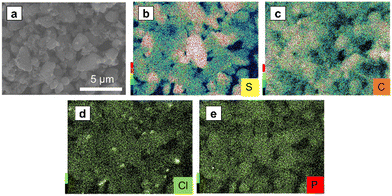 | ||
| Fig. 7 (a) The SEM images of SE–S–C under an Ar atmosphere, and the EDS mapping of (b) S, (c) C, (d) Cl, and (e) P. | ||
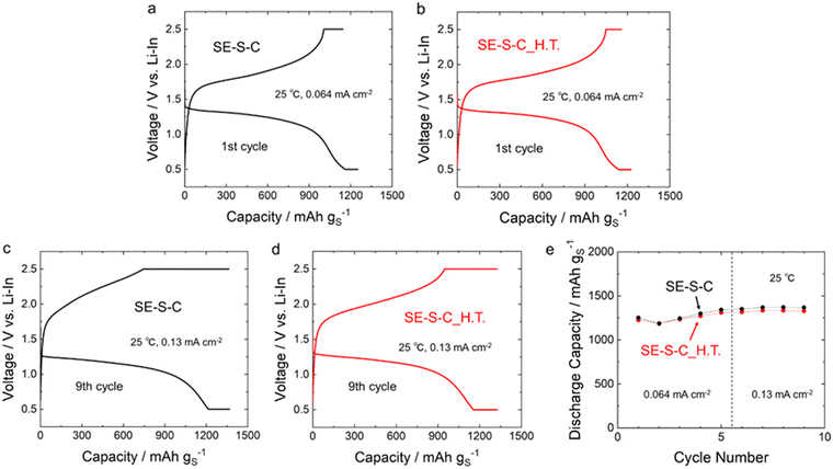
Fig. 8a–d shows the 1st and 9th discharge–charge curves of the all-solid-state Li–S batteries with the sulphur composite cathodes prepared by adding the 60Li2S·40P2S5 solid electrolyte into SE–S–C/SE–S–C_H.T. Fig. 8e shows the cycling performance of these batteries. The measurements for both batteries were performed under the current density of 0.064 mA cm−2 and 0.13 mA cm−2 at 25 °C. These batteries exhibited similar discharge–charge behaviour, and the discharge and charge capacities were almost the same as shown in Table 1 and Fig. 8e, although the charging voltage reached the cut-off voltage (2.5 V (vs. Li–In)) a little early at the 9th charge when using SE–S–C_H.T. This result suggests that even solution impregnation alone, without the melt-diffusion process, can form a favourable contact between sulphur and carbon.
| Cathode | 1st cycle | 9th cycle | ||
|---|---|---|---|---|
| Discharge capacity/mA h g−1 | Charge capacity/mA h g−1 | Discharge capacity/mA h g−1 | Charge capacity/mA h g−1 | |
| SE–S–C | 1252 | 1144 | 1367 | 1363 |
| SE–S–C_H.T. | 1225 | 1157 | 1327 | 1325 |
Conclusions
A sulphur–carbon composite was prepared by impregnating porous carbon with sulphur using sulphur solution, and the effect of the melt-diffusion after solution impregnation on the properties as the cathode for all-solid-sate Li–S batteries was investigated. The specific surface areas of the sulphur–carbon composite prepared by solution impregnation with and without melt-diffusion were 11 m2 g−1 and 7.6 m2 g−1, which were significantly lower than the value of raw material carbon, 1.3 × 10³ m2 g−1. This suggests that most of the entrance of the carbon pores can be filled with sulphur by solution impregnation alone. The all-solid-state Li–S batteries assembled using the cathode composites, which were prepared by mixing the sulphur composites and sulphide solid electrolytes, exhibited the discharge–charge behaviour. The capacities were almost the same with and without the melt-diffusion process after sulphur solution impregnation. Thus, the sulphur–carbon composite prepared by solution impregnation, even without melt-diffusion, would be effective for all-solid-state Li–S batteries, which require efficient conductive paths with as few conductive additives as possible.Conflicts of interest
There are no conflicts to declare.Acknowledgements
The authors thank Mr Hikaru TOKIWA for his support for the charge–discharge measurement.References
- M. Armand and J.-M. Tarascon, Nature, 2008, 451, 652–657 CrossRef PubMed.
- J. B. Goodenough and Y. Kim, Chem. Mater., 2010, 22, 587–603 CrossRef.
- P. G. Bruce, S. A. Freunberger, L. J. Hardwick and J. M. Tarascon, Nat. Mater., 2012, 11, 19–29 CrossRef.
- T. Kim, W. Song, D. Y. Son, L. K. Ono and Y. Qi, J. Mater. Chem. A, 2019, 7, 2942–2964 RSC.
- A. Manthiram, Y. Fu, S. H. Chung, C. Zu and Y. S. Su, Chem. Rev., 2014, 114, 11751–11787 CrossRef PubMed.
- Z. W. Seh, Y. Sun, Q. Zhang and Y. Cui, Chem. Soc. Rev., 2016, 45, 5605–5634 RSC.
- H. J. Peng, J. Q. Huang, X. B. Cheng and Q. Zhang, Adv. Energy Mater., 2017, 7, 1700260 CrossRef.
- X. Ji, K. T. Lee and L. F. Nazar, Nat. Mater., 2009, 8, 500–506 CrossRef.
- D.-W. Wang, Q. Zeng, G. Zhou, L. Yin, F. Li, H.-M. Cheng, I. R. Gentle and G. Q. M. Lu, J. Mater. Chem. A, 2013, 1, 9382–9394 RSC.
- D. W. Susanne, M. Hagen, H. Althues, J. Tübke, S. Kaskel and M. J. Hoffmann, Chem. Commun., 2012, 48, 4097–4099 RSC.
- G. Zheng, Q. Zhang, J. J. Cha, Y. Yang, W. Li, Z. Wei She and Y. Cui, Nano Lett., 2013, 13, 1265–1270 CrossRef PubMed.
- X. Li, Y. Wang, C. Xu and L. Pan, J. Solid State Electrochem., 2017, 21, 1101–1109 CrossRef.
- C. Oh, N. Yoon, J. Choi, Y. Choi, S. Ahn and J. K. Lee, J. Mater. Chem. A, 2017, 5, 5750–5760 RSC.
- D. Gueon, M.-Y. Ju and J. H. Moon, Proc. Natl. Acad. Sci. U. S. A., 2020, 117, 12686–12692 CrossRef.
- A. Hayashi, T. Ohtomo, F. Mizuno, K. Tadanaga and M. Tatsumisago, Electrochem. Commun., 2003, 5, 701–705 CrossRef.
- M. Nagao, A. Hayashi and M. Tatsumisago, Electrochim. Acta, 2011, 56, 6055–6059 CrossRef.
- J. Wu, S. Liu, F. Han, X. Yao, C. Wang, J. Wu, X. Yao, S. Liu, F. Han and C. Wang, Adv. Mater., 2021, 33, 2000751 CrossRef PubMed.
- N. Kamaya, K. Homma, Y. Yamakawa, M. Hirayama, R. Kanno, M. Yonemura, T. Kamiyama, Y. Kato, S. Hama, K. Kawamoto and A. Mitsui, Nat. Mater., 2011, 10, 682–686 CrossRef.
- Y. Kato, S. Hori, T. Saito, K. Suzuki, M. Hirayama, A. Mitsui, M. Yonemura, H. Iba and R. Kanno, Nat. Energy, 2016, 1, 1–7 Search PubMed.
- A. Sakuda, A. Hayashi and M. Tatsumisago, Sci. Rep., 2013, 3, 2261 CrossRef PubMed.
- X. Sun, Q. Li, D. Cao, Y. Wang, A. Anderson and H. Zhu, Small, 2022, 18, 2105678 CrossRef CAS.
- B. Chen, S. Deng, M. Jiang, M. Wu, J. Wu and X. Yao, Chem. Eng. J., 2022, 448, 1385–8947 Search PubMed.
- A. Miura, N. C. Rosero-Navarro, A. Sakuda, K. Tadanaga, N. H. H. Phuc, A. Matsuda, N. Machida, A. Hayashi and M. Tatsumisago, Nat. Rev. Chem., 2019, 3, 189–198 CrossRef CAS.
- M. Calpa, N. C. Rosero-Navarro, A. Miura and K. Tadanaga, RSC Adv., 2017, 7, 46499–46504 RSC.
- R. Maniwa, M. Calpa, N. C. Rosero-Navarro, A. Miura and K. Tadanaga, J. Mater. Chem. A, 2021, 9, 400–405 RSC.
- N. C. Rosero-Navarro, A. Miura and K. Tadanaga, J. Sol-Gel Sci. Technol., 2019, 89, 303–309 CrossRef CAS.
- M. Calpa, N. C. Rosero-Navarro, A. Miura and K. Tadanaga, J. Sol-Gel Sci. Technol., 2022, 101, 8–15 CrossRef CAS.
- H. Nagata and Y. Chikusa, J. Power Sources, 2014, 263, 141–144 CrossRef CAS.
| This journal is © The Royal Society of Chemistry 2024 |


