 Open Access Article
Visible-light driven fumarate synthesis from pyruvate and gaseous CO2 with a hybrid system of photocatalytic NADH regeneration and dual biocatalysts†
Mika
Takeuchi
a and
Yutaka
Amao
 *ab
*ab
aGraduate School of Science, Osaka Metropolitan University, 3-3-138 Sugimoto, Sumiyoshi-ku, Osaka 558-8585, Japan
bResearch Centre of Artificial Photosynthesis (ReCAP), Osaka Metropolitan University, 3-3-138 Sugimoto, Sumiyoshi-ku, Osaka 558-8585, Japan. E-mail: amao@omu.ac.jp
First published on 7th September 2023
Abstract
Fumarate is a useful unsaturated dicarboxylate utilized as a precursor for unsaturated polyester resin and biodegradable plastics. Fumarate is partially produced from petroleum-derived materials; thus, it is necessary to establish a synthesis from renewable raw materials such as gaseous CO2 and biobased compounds with an external renewable energy source such as solar light. In this work, the visible-light driven synthesis of fumarate from biobased pyruvate is reported, which uses CO2 directly captured from the gas phase by a 4-(2-hydroxyethyl)-1-piperazineethanesulfonic acid (HEPES)–NaOH buffer solution in combination with the NAD+ reduction system of triethanolamine (TEOA), water-soluble zinc porphyrin, zinc meso-tetra(4-sulfonatophenyl) porphyrin tetrasodium salt (ZnTPPS) and the Rh coordination complex ([Cp*Rh(bpy)(H2O)]2+; Cp* = pentamethylcyclopentadienyl, bpy = 2,2′-bipyridyl). In addition, dual-biocatalysts consisting of malate dehydrogenase (oxaloacetate-decarboxylating; MDH; EC 1.1.1.38) from Sulfobus tokodaii and fumarase from porcine heart (FUM; EC 4.2.1.2) were used. It was found that pyruvate can be converted into L-malate with MDH by directly using CO2 gas as a carboxylating agent in the presence of NADH. Moreover, the development of visible-light driven fumarate synthesis from gaseous CO2 and pyruvate, employing a system with NADH regeneration and dual-biocatalysts as raw materials was also established.
Sustainability spotlightThis research focuses on synthesizing precursors for biodegradable polymers from gaseous CO2 and biomass-derived molecules using visible-light energy and dual-biocatalysts in aqueous media under mild conditions compared with the conventional industrial method for the synthesis of precursors for biodegradable polymers. Therefore, this research contributes to CO2 fixation and to alternative plastic precursor production for a more sustainable society. This system can fix gaseous CO2 into organic molecules and convert it into high-value-added materials, resulting in long-term storage of CO2 in molecules. This work aligns with the UN's Sustainable Development Goals, particularly Goal 7 “Affordable and Clean Energy” and 12 “Responsible Consumption and Production”. |
Introduction
Carbon capture utilization and sequestration (CCUS) technology aims to reduce CO2 emissions. CCUS basically captures CO2 released from power plants, factories, and fuel-burning industrial facilities and physically stores it geologically or converts it into useful materials.1–5 In CCUS technologies, CO2 can also be used as a raw material to produce C1 based fuels, chemicals, and polymers.6 One key issue facing CCUS technologies is research and development of effective catalysts for CO2 conversion into useful materials. Investigation and development of effective catalysts for converting CO2 into useful materials is a pressing and important challenge in CCUS technology. Among the various catalysts, biocatalysts with the function of CO2 conversion are also attracting a great deal of attention in CCUS technology. Biocatalysts with the function of CO2 conversion are classified into two categories: those which reduce CO2 to form C1 compounds such as CO or formate and those which build C–C bonds from CO2 and organic molecules to produce carboxylate. CO2, the final combustion product of carbohydrates, shows high stability but low reactivity, so external energy is required to convert it into useful materials.7–12 Studies on visible light-driven CO2 conversion systems, which hybridize a biocatalyst with a photoredox system consisting of a dye molecule or a photocatalyst and an electron mediator have been reported.7,13–15 In particular, many studies have reported hybrid systems of formate dehydrogenase (FDH), which catalyzes the reduction of CO2 to formate in the presence of NADH and photoredox systems.16–31 On the other hand, visible-light driven CO2 fixation to organic molecules has also garnered much attention in the research field of green chemistry.7–12 For example, CO2 as a feedstock is bound to an organic molecule as a carboxy-group based on building C–C bonds to produce a carboxylate. Malate dehydrogenase, decarboxylating (EC 1.1.1.39)32,33 or oxaloacetate-decarboxylating (EC 1.1.1.40)34,35 is an enzyme that catalyzes the reaction of decarboxylating L-malate into pyruvate and CO2 and the reverse reaction of the introduced CO2 as a carboxy-group to pyruvate to form L-malate in the presence of NAD(P)+/NAD(P)H. Some studies on the visible-light driven L-malate production from pyruvate and bicarbonate with a system of an electron donor (D), a photosensitizer (P), methylviologen (MV) as an electron mediator, ferredoxin-NADP+ reductase (FNR), NAD(P)+ and MDH as shown in Fig. 1 have been reported.36–38L-Malate is used in various applications in the food industry as an acidulant, pH adjuster and emulsifier. In contrast, poly(L-malic acid) (PMLA) polymerized with L-malate as a precursor (Fig. 2) has the outstanding features of biocompatibility, biodegradability, water solubility, and non-immunogenicity, and can be easily chemically modified.39–44
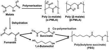 | ||
| Fig. 2 Chemical structures of 3-hydroxybutyrate, poly-3-hydroxybutyrate (PHB) and poly (3-hydroxybutyrate)-co-(hydroxyvalerate) (PHB-co-PHV). | ||
One candidate for the more effective use of L-malate synthesized from CO2 is conversion to fumarate with a higher added value by intramolecular dehydration. Fumarate, an unsaturated dicarboxylic acid, is a chemical building block with many uses, including in the polymer industry.45–49 In the field of polymer chemistry, fumarate is useful as a precursor for biodegradable plastic poly (butylene succinate) (PBS)50 as shown in Fig. 2.
In the system shown in Fig. 1, visible light-driven regeneration of NAD(P)H was achieved. However, this system is very complicated. Moreover, FNR used in this system is a very expensive biological reagent. Thus, it is necessary to simplify it by using a novel catalyst instead of FNR for selective NAD(P)+ reduction to NAD(P)H. The Rh complex ([Cp*Rh(bpy)(H2O)]2+; Cp* = pentamethylcyclopentadienyl, bpy = 2,2′-bipyridyl) and colloidal Rh nanoparticles are candidates for selective reduction of NAD(P)+ to NAD(P)H.51–55
We previously reported biocatalytic fumarate production from bicarbonate and pyruvate viaL-malate as an intermediate with two biocatalysts malate dehydrogenase (NAD+-dependent oxaloacetate-decarboxylating; MDH EC 1.1.1.38) and fumarase (FUM; EC 4.2.1.2) in the presence of NADH in aqueous media, and the conversion yield for pyruvate to fumarate was estimated to be 14.4% after 25 h.56,57 Since this system uses NADH as a sacrificial reagent, it is necessary to integrate the NAD+ into NADH regeneration system. Thus, visible-light driven fumarate production from pyruvate and bicarbonate with the combination of NAD+ reduction to the NADH system of triethanol amine (TEOA) as an electron donor, a water-soluble zinc porphyrin, zinc meso-tetra(4-sulfonatophenyl)porphyrin tetrasodium salt (ZnTPPS) as a photosensitizer and [Cp*Rh(bpy)(H2O)]2+, as well as dual biocatalysts (MDH and FUM) has also been reported, as shown in Fig. 3.58
In this system, bicarbonate was used as a carboxylating agent for pyruvate instead of CO2. For this reason, the MDH-catalyzed pyruvate carboxylation process requires bicarbonate.
Therefore, we devised the direct utilization of CO2 gas instead of bicarbonate in the visible-light driven fumarate synthesis as a CO2 capture and utilization (CCU) system, as shown in Fig. 3. One of the candidates for capturing gaseous CO2 in an aqueous solution is a method using a basic aqueous solution containing amines. It was found that a pH of the reaction solution above pH 7.0 was optimal for the visible light-driven NADH regeneration in the system shown in Fig. 3. Furthermore, it was also reported that the enzymatic activities of MDH and FUM were optimal between pH 7.0 and 7.5 of the reaction solution. In other words, by using a weakly basic buffer such as 4-(2-hydroxyethyl)-1-piperazineethanesulfonic acid (HEPES)–NaOH solution in the system shown in Fig. 3, CO2 in the gas phase can be directly captured and converted to bicarbonate.59
In this study, the visible-light driven fumarate synthesis from pyruvate and CO2 directly captured from the gas phase by a HEPES–NaOH buffer solution with the combination of the NAD+ reduction system of TEOA, ZnTPPS and [Cp*Rh(bpy)(H2O)]2+, as well as MDH and FUM was investigated.
Experimental
Materials
NAD+ and NADH were purchased from Oriental Yeast Co., Ltd. Sodium pyruvate, sodium bicarbonate, magnesium chloride hexahydrate and triethanolamine (TEOA) were purchased from FUJIFILM Wako Pure Chemical Corporation. (Pentamethylcyclopentadienyl) rhodium(III) dichloride dimer ([Cp*RhCl2]2) and 2,2′-bipyridyl were purchased from Tokyo Chemical Industry Co., Ltd. Zinc meso-tetra(4-sulfonatophenyl) porphyrin tetrasodium salt (ZnTPPS) was purchased from Frontier Scientific Inc. 4-(2-Hydroxyethyl)-1-piperazineethanesulfonic acid (HEPES) was purchased from NACALAI TESQUE, INC. Malate dehydrogenase decarboxylating type (MDH, EC 1.1.1.38 code: MDH-73-01 was obtained from Sulfobus tokodaii; the commercially available reagent, 14 mg mL−1; 0.55 units mg−1) was purchased from Thermostable Enzyme Laboratory Co., Ltd. One activity unit of ME converted 1.0 μmol of NADH to NAD+ in the presence of 10 mM sodium pyruvate, 0.3 mM NADH, 10 mM sodium bicarbonate and 10 mM magnesium chloride in 50 mM 1,4-piperazinediethanesulfonic acid–KOH buffer per min at pH 6.5 at 37 °C, according to the data sheet provided by Thermostable Enzyme Laboratory Co., Ltd. The molecular weight of ME was estimated to be 40 kDa based on the SDS-page using electrophoresis. Fumarase (FUM) from porcine heart (EC 4.2.1.2; molecular weight: 200 kDa)60,61 was purchased from Merck Co., Ltd. One activity unit of FUM converted 1.0 μmol of L-malate to fumarate in potassium phosphate buffer per min at pH 7.6 at 25 °C.Pentamethylcyclopentadienyl(2,2′-bipyridyl)rhodium(III) chloride ([Cp*Rh(bpy)(H2O)]2+) was synthesized from [Cp*RhCl2]2 and 2,2′-bipyridine according to a previous report.62
Estimation of the amount of CO2 in the gas phase captured in a sample solution
The estimation method for CO2 in the gas phase captured in the sample solution are as follows. The reaction is an isobaric system, as shown in Fig. 4.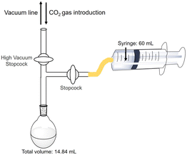 | ||
| Fig. 4 Outline of the experimental setup for the estimation of the amount of CO2 in the gas phase captured in a sample solution. | ||
The HEPES–NaOH buffer (500 mM; pH 7.8) was used as a sample solution. The sample solution was deaerated by freeze–pump–thaw cycles repeated 6 times and then flushed in the gas phase and syringed with the CO2 gas. The total pressure was maintained at 1.01325 × 10⁵ Pa. The volume change in the syringe was measured and the amount of CO2 dissolved in the liquid phase was estimated. Here, CO2 was regarded as a real gas, and the amount of CO2 (n) in the gas phase was calculated using the following eqn (1).
 | (1) |
Kinetic parameters for L-malate production from pyruvate and bicarbonate with MDH in the presence of NADH
The reaction mixture consisted of sodium pyruvate (5.0 mM), magnesium chloride (10 mM), NADH (5.0 mM), sodium bicarbonate and MDH (0.7 U; ca. 1.6 μM) in 5.0 mL of 500 mM HEPES buffer–NaOH (pH 7.0). The concentration of sodium bicarbonate was varied from 0 to 100 mM. The amount of L-malate produced was detected by ion chromatography (Metrohm, Eco IC; electrical conductivity detector) with an ion exclusion column (Metrosep Organic Acids 250/7.8 Metrohm; column size: 7.8 × 250 mm; composed of 9 μm polystyrene–divinylbenzene copolymer with sulfonic acid groups). Details of pyruvate or L-malate quantification by ion chromatography are described in the ESI.† The pyruvate and L-malate concentration were determined from the calibration curve based on the chromatogram of a standard sample (Fig. S1 and S2†) using the eqn (S1) and (S2).† The concentration of L-malate production for 30 min was estimated as the initial rate.L-Malate production from the pyruvate and directly captured CO2 with MDH
The reaction mixture consisted of sodium pyruvate (5.0 mM), magnesium chloride (5.0 mM), NADH (5.0 mM) and MDH (0.7 U; ca. 1.6 μM) in 5.0 mL of 500 mM HEPES buffer–NaOH (pH 7.8). The reaction vessel is a clear glass vial (11.0 mL) and an isobaric system by feeding CO2 gas into the vessel gas phase. The total pressure was maintained at 1.01325 × 10⁵ Pa. The amount of pyruvate or L-malate was detected by ion chromatography.Fumarate synthesis from the pyruvate and directly captured CO2 with MDH and FUM
The reaction mixture consisted of sodium pyruvate (5.0 mM), magnesium chloride (5.0 mM), NADH (5.0 mM), MDH (0.7 U; 1.6 μM) and FUM (0.5 U; 1.3 nM) in 5.0 mL of 500 mM HEPES–NaOH buffer (pH 7.8). This reaction is also an isobaric system similar to the above. The total pressure was maintained at 1.01325 × 10⁵ Pa. The concentrations of pyruvate, L-malate and fumarate were detected by ion chromatography. The fumarate concentration was determined from the calibration curve based on the chromatogram of a standard sample (Fig. S3†) using the eqn (S3).†Visible-light driven NAD+ reduction to NADH with a system of TEOA, ZnTPPS and [Cp*Rh(bpy)(H2O)]2+ under various pH conditions
The reaction mixture consisted of TEOA (0.2 M), ZnTPPS (10 μM), [Cp*Rh(bpy)(H2O)]2+ (10 μM) and NAD+ (0.5 mM) in 5.0 mL of 500 mM HEPES–NaOH buffer. The pH of the sample solution was varied from 6.4 to 8.1. The reaction is an isobaric system as shown in Fig. 5. The sample solution was deaerated by freeze–pump–thaw cycles repeated 6 times and then flushed in the gas phase with Ar gas for 10 min. The sample solution was irradiated with a 250 W halogen lamp (Panasonic) as a visible-light source (light intensity: 200 J m−2 s−1) at 30 °C. The concentration of NADH was monitored by the absorption spectrum change using UV-visible absorption spectroscopy (SHIMADZU, MaltiSpec-1500) with the molar coefficient at 340 nm (ε = 6220 cm−1 M−1).63 The concentration of NADH production for 30 min was estimated as the initial rate.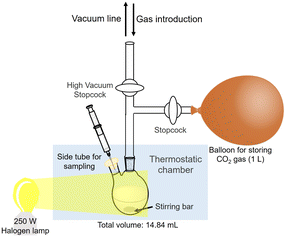 | ||
| Fig. 5 Outline of the experimental setup of the isobaric system utilized for direct capture of CO2 gas. | ||
Visible-light driven L-malate synthesis from pyruvate and direct capture of CO2 with the system of TEOA, ZnTPPS, [Cp*Rh(bpy)(H2O)]2+, NAD+ and MDH
The reaction mixture consisted of sodium pyruvate (5.0 mM), magnesium chloride (5.0 mM), TEOA (0.2 M), ZnTPPS (10 μM), [Cp*Rh(bpy)(H2O)]2+ (10 μM), NAD+ (0.5 mM) and MDH (0.7 U; 1.6 μM) in 5.0 mL of 500 mM HEPES–NaOH buffer (pH 7.8). The sample solution was deaerated by freeze–pump–thaw cycles repeated 6 times and then flushed in the gas phase and a balloon with CO2 gas for 10 min. The sample solution was irradiated with a 250 W halogen lamp as a visible-light source (light intensity: 200 J m−2 s−1) at 30 °C. The reaction is also an isobaric system, as shown in Fig. 5. The total pressure was maintained at 1.01325 × 10⁵ Pa. The concentration of L-malate was detected by ion chromatography using the eqn (S2).†Visible-light driven fumarate synthesis from pyruvate and directly captured CO2 with the system of TEOA, ZnTPPS, [Cp*Rh(bpy)(H2O)]2+, NAD+, MDH and FUM
The reaction mixture consisted of sodium pyruvate (5.0 mM), magnesium chloride (5.0 mM), TEOA (0.2 M), ZnTPPS (10 μM), [Cp*Rh(bpy)(H2O)]2+ (10 μM), NAD+ (0.5 mM), MDH (0.7 U; 1.6 μM) and FUM (0.5 U; 1.3 nM) in 5.0 mL of 500 mM HEPES–NaOH buffer (pH 7.8). The sample solution was deaerated by freeze–pump–thaw cycles repeated 6 times and then flushed in the gas phase and a balloon with the mixture gas of N2 and CO2 prepared in a mixing chamber for 10 min. The sample solution was irradiated with a 250 W halogen lamp (light intensity: 200 J m−2 s−1) as a visible-light source at 30.5 °C. The reaction is also an isobaric system as shown in Fig. 5. The total pressure was maintained at 1.01325 × 10⁵ Pa. The concentrations of L-malate and fumarate were detected by ion chromatography using the eqn (S2) and (S3).†Results and discussion
Estimation of the capture of CO2 in the gas phase into a sample solution
Fig. 6 shows the time dependence of the volume (ΔV) of the syringe of the experimental apparatus shown in Fig. 4. As shown in Fig. 6, the volume of the syringe decreased with increasing incubation time. Fig. 6 also shows the result of calculating the amount of CO2 from the volume change of the syringe using eqn (1). In addition, it is predicted that CO2 is more soluble in aqueous media more than pH 7. Therefore, the observed volume decrease is due to the dissolution of CO2 gas into the buffer solution.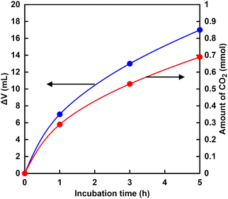 | ||
Fig. 6 Time dependence of the volume change (ΔV) of the syringe of the experimental apparatus ( ) and calculating the amount of CO2 from the volume change of the syringe ( ) and calculating the amount of CO2 from the volume change of the syringe ( ). ). | ||
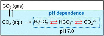
As shown in Fig. 6, the amount of CO2 dissolved into the HEPES buffer solution was estimated to be ca. 0.7 mmol (ca. 140 mM in 5.0 mL of buffer solution). The results of this experiment indicated that CO2 in the gas phase was captured in the sample solution over time by HEPES buffer. Here, CO2 gas dissolves in aqueous media and then the hydrated CO2 reacts with water to produce H2CO3. Dissociation of H2CO3 produces bicarbonate and carbonate depending on the pH of the solution, as shown in Fig. 7.64
The distribution ratio of CO2 (aq) and bicarbonate were estimated to be ca. 18 and 82% at pH 7.0 calculated using the Plummer and Busenberg equation.65 As shown in Fig. 6, the estimated CO2 concentration was calculated to be 140 mM. Thus, the bicarbonate concentration was estimated to be 115 mM in the HEPES buffer solution (pH 7.0).
Next, the bicarbonate concentration required for the MDH catalytic reaction was determined by using Michaelis–Menten analysis and the possibility of using CO2 gas captured into a sample solution from the gas phase as a raw material was also investigated. Fig. 8 shows the relationship between the sodium bicarbonate concentration and the initial rate for L-malate production with MDH (v0). The v0 was calculated from the concentration of L-malate production with MDH after 30 min incubation. As shown in Fig. 8, the v0 was increased with increasing sodium bicarbonate concentration until 50 mM and then was saturated. The plot in Fig. 8 obeyed the Michaelis–Menten relationship. The Michaelis–Menten constant Km and the maximum rate (Vmax) of MDH for carboxylation of pyruvate with bicarbonate was estimated to be 14 mM and 0.03 mM min−1. Therefore, it is estimated that the concentration of bicarbonate produced from CO2 captured by HEPES from the gas phase into the sample solution has about 8.2 times the Km of MDH.
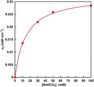 | ||
| Fig. 8 Relationship between the sodium bicarbonate concentration and the initial rate for L-malate production with MDH (v0). | ||
In general, a substrate concentration three times higher than the Km value is required for a stable enzymatic reaction. Thus, it was suggested that the bicarbonate captured from CO2 gas could be used in MDH-catalyzed carboxylation of pyruvate L-malate production.
L-Malate synthesis from the pyruvate and directly captured CO2 with MDH
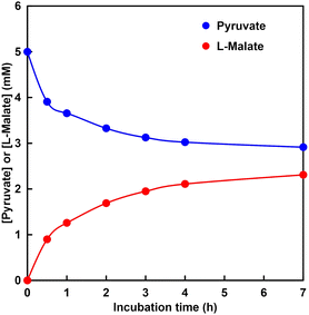
Fig. 9 shows the time dependence of the concentration of pyruvate or L-malate with MDH in HEPES–NaOH buffer (the ion chromatograph chart during the reaction is shown in Fig. S4†).The gas phase was filled with 100% CO2. The L-malate concentration was increased with increasing incubation time. In contrast, the pyruvate concentration decreased with increasing incubation time. After 7 h incubation, the L-malate concentration was estimated to be 2.3 mM. The conversion yield for pyruvate to L-malate was estimated to be 46%. The initial reaction rate in this system was estimated to be 0.03 mM min−1. On the other hand, the Vmax of MDH for the carboxylation of pyruvate with bicarbonate was calculated to be 0.03 mM min−1 under the condition of 5.0 mM pyruvate from the result of Fig. 8. These results indicate that pyruvate is carboxylated using gaseous CO2 as a starting material instead of bicarbonate.
Fumarate synthesis from the pyruvate and directly captured CO2 with MDH and FUM
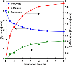
Fig. 10 shows the time dependence of the concentration of pyruvate, L-malate or fumarate with MDH and FUM in HEPES–NaOH buffer (the ion chromatograph chart during the reaction is shown in Fig. S5†). The gas phase was filled with 100% CO2.L-Malate and fumarate concentrations increased with incubation time. On the other hand, pyruvate concentration decreased with incubation time. After 7 h incubation, the concentration of fumarate produced was estimated to be 0.61 mM. The conversion yield for pyruvate to fumarate was estimated to be ca. 12% after 7 h incubation. On the other hand, in a fumarate synthesis system using sodium bicarbonate as a raw material under the same conditions, the concentration of fumarate produced and the conversion yield after 7 h incubation are reported to be 0.65 mM and ca. 13%, respectively. It was shown that there is no significant difference between the two systems. Thus, it shows that CO2 in the gas phase can be used directly as a carboxylating agent for pyruvate instead of bicarbonate.
The pH dependence of visible-light driven NAD+ reduction to NADH with the system of TEOA, ZnTPPS and [Cp*Rh(bpy)(H2O)]2+
The NADH production rate is an important factor rather than the NADH accumulation concentration within a certain period of time in the visible-light driven fumarate or L-malate synthesis from pyruvate and gaseous CO2. Fig. 11 shows the NADH production rate (v) in the system of TEOA, ZnTPPS and [Cp*Rh(bpy)(H2O)]2+ under various pH conditions.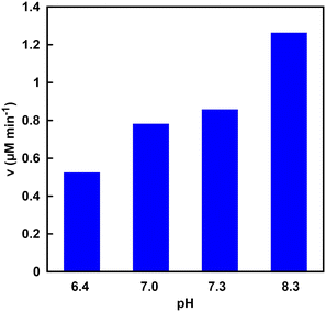 | ||
| Fig. 11 Visible-light driven NADH production rate (v) in the system of TEOA, ZnTPPS and [Cp*Rh(bpy)(H2O)]2+ under various pH conditions. | ||
As shown in Fig. 11, it was found that the rate of NADH production increased with increasing the pH of the sample solution. This phenomenon is due to the ionization of the nitrogen atom of TEOA as an electron donor. Fig. 12 shows the single-electron transfer (SET) process from TEOA to the accepter molecule.
 | ||
| Fig. 12 The relationship between protonated TEOA (TEOAH+) and TEOA, and the single-electron oxidation process to produce TEOAox. | ||
As shown in Fig. 12, TEOAox is produced by releasing a single electron of the lone pair on the nitrogen atom of TEOA. Thus, it is suggested that the electron donating capability of TEOAH+ without a lone pair on the nitrogen decreases. The pKa of TEOAH+ was reported to be 7.54 at 30 °C.66 As the pH of the sample solution increased, thus, the distribution of TEOA increased, resulting in an increase in the NADH production rate. Although the visible-light driven reduction of NAD+ depends on the pH of the sample solution, NADH was regenerated from NAD+ by visible light irradiation even under neutral pH conditions, which is the optimal pH for MDH and FUM (pH 7.0–7.5). These results suggest that the visible-light driven reduction of the NAD+ system is applicable to hybridize the dual-biocatalysts.
Visible-light driven L-malate synthesis from pyruvate and directly captured CO2 with the system of TEOA, ZnTPPS, [Cp*Rh(bpy)(H2O)]2+, NAD+ and MDH
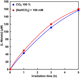
The visible-light driven L-malate synthesis from pyruvate and bicarbonate with the system of sodium pyruvate, magnesium chloride, TEOA, ZnTPPS, [Cp*Rh(bpy)(H2O)]2+, NAD+, and MDH has been reported previously. Therefore, utilization of directly captured CO2 gas instead of bicarbonate in this system was investigated. Fig. 13 shows the time dependence of L-malate concentration in the sample solution of sodium pyruvate, magnesium chloride, TEOA, ZnTPPS, [Cp*Rh(bpy)(H2O)]2+, NAD+, and MDH under irradiation (the ion chromatography chart during the reaction is shown in Fig. S6†). The gas phase was filled with CO2 gas. Fig. 13 also shows the time dependence of the L-malate concentration in the sample solution of sodium pyruvate, magnesium chloride, TEOA, ZnTPPS, [Cp*Rh(bpy)(H2O)]2+, NAD+, sodium bicarbonate and MDH under irradiation. In this system, the gas phase was also filled with CO2 gas.As shown in Fig. 13, L-malate concentration increased constantly over the irradiation time and 157 μM of L-malate was produced after 5 h. This linear increase in L-malate over the irradiation time indicates that bicarbonate was captured from CO2 gas continuously and fixed to pyruvate with MDH in the presence of NADH produced by visible light irradiation. As shown in Fig. 13, it was shown that there is no significant difference between the systems using bicarbonate and CO2 gas as a carboxylating agent for pyruvate. In addition, the catalytic turnover number of MDH in the visible-light driven L-malate synthesis was estimated to be 100, suggesting that CO2 fixation to pyruvate proceeded effectively with MDH. From these results, it can also be seen that CO2 in the gas-phase can be used directly as a carboxylating agent for pyruvate instead of bicarbonate in the visible-light driven L-malate synthesis. However, compared to the system using NADH as a sacrificial reagent, as shown in Fig. 9, the efficiency of the visible light-driven L-malate synthesis is low. This is presumed to be due to the slow visible light reduction rate of NAD+ in the system of TEOA, ZnTPPS, and [Cp*Rh(bpy)(H2O)]2+.
Visible-light driven fumarate synthesis from pyruvate and directly captured CO2 with the system of TEOA, ZnTPPS, [Cp*Rh(bpy)(H2O)]2+, NAD+, MDH and FUM
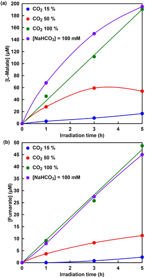
Finally, visible-light driven fumarate synthesis from pyruvate and directly captured CO2 with the system of TEOA, ZnTPPS, [Cp*Rh(bpy)(H2O)]2+, NAD+, MDH and FUM was investigated.Fig. 14 shows the time dependence of L-malate (a) and fumarate (b) concentration in the sample solution of sodium pyruvate, magnesium chloride, TEOA, ZnTPPS, [Cp*Rh(bpy)(H2O)]2+, NAD+, MDH and FUM with a mixed gas with different mixing ratios of CO2 and N2 under irradiation (the ion chromatography chart during the reaction is shown in Fig. S7†). As shown in Fig. 14, the L-malate and fumarate concentrations increase with the irradiation time under all conditions. It was clarified that concentration of visible-light driven fumarate synthesis depends on CO2 gas concentration in the gas phase. No significant difference in fumarate synthesis was observed under 100% CO2 in the gas phase and the presence of sodium bicarbonate conditions. On the other hand, the synthesis of L-malate and fumarate with the visible-light driven system decreased under the conditions of CO2 concentration of 50 or 15% in the gas phase. The first step in the visible-light driven fumarate synthesis, the dissolution process of CO2, requires a supply of bicarbonate, which is necessary for the MDH-catalyzed carboxylation of pyruvate to produce L-malate. As shown in Fig. 14, under the conditions of a CO2 concentration of 50 or 15%, not only fumarate synthesis but also L-malate synthesis greatly depends on the gas-phase CO2 concentration. Thus, it is proposed that the low concentration of L-malate synthesis is due to the low CO2 gas concentration in the gas phase and the slow dissolution rate in the reaction solution. Next, let us compare L-malate synthesis in the visible-light driven fumarate synthesis under 100% CO2 in the gas phase and the presence of sodium bicarbonate conditions. Under the presence of sodium bicarbonate conditions, the initial rate of L-malate synthesis in the visible-light driven fumarate synthesis is higher than that under 100% CO2 in the gas phase condition. This is presumed to be due to the fact that the MDH-catalyzed carboxylation of pyruvate under the condition of 100% CO2 involves the dissolution of CO2 in the gas phase into the reaction solution and the production of bicarbonate. On the other hand, there was no significant difference between under 100% CO2 in the gas phase and the presence of sodium bicarbonate conditions in the FUM-catalyzed fumarate synthesis. After 5 h irradiation, moreover, the ratios of L-malate and fumarate production concentrations under 15, 50 and 100% CO2 in the gas phase are estimated to be 0.14, 0.29 and 0.26, respectively. These results suggest that the rate-limiting step in the overall reaction system is fumarate synthesis based on FUM-catalyzed dehydration of L-malate. Thus, CO2 could be directly used as a raw material without using bicarbonate, because of CO2 in the gas-phase trapping function of the HEPES buffer solution used in the reaction. Additionally, the captured CO2 was converted to bicarbonate in the HEPES buffer and acted as a carboxylating agent for pyruvate with MDH. In order to improve fumarate synthesis efficiency, it is necessary to investigate the effect of each reaction element in the visible-light driven system on FUM catalytic activity.
Conclusions
In conclusion, we have demonstrated visible-light driven fumarate synthesis from pyruvate and CO2 captured from the gas phase using HEPES–NaOH buffer solution with the combination of the NAD+ reduction system of TEOA, ZnTPPS and [Cp*Rh(bpy)(H2O)]2+, as well as dual biocatalysts of MDH and FUM without any bicarbonate. It was shown that pyruvate can be converted into L-malate with MDH by directly using CO2 gas as a carboxylating agent in the presence of NADH. Moreover, the development of the visible light-driven fumarate synthesis from gaseous CO2 and biobased pyruvate as raw materials with the combination of a NAD+ reduction system of TEOA, ZnTPPS and [Cp*Rh(bpy)(H2O)]2+, as well as dual biocatalysts of MDH and FUM was accomplished. Notably, no significant difference was observed between under 100% CO2 in the gas phase and the presence of sodium bicarbonate conditions as a raw material in the visible light-driven fumarate synthesis. This system is the first example of achieving direct gaseous CO2 fixation into pyruvate using the electron accumulation in NAD+ with visible-light energy.Conflicts of interest
There are no conflicts to declare.Acknowledgements
This work was partially supported by Grant-in-Aid for Scientific Research (B) (22H01872) and (22H01871), the Fund for the Promotion of Joint International Research (Fostering Joint International Research (B)) (19KK0144), and by the Institute for Fermentation, Osaka (IFO) (G-2023-3-050).Notes and references
- A. Abdulla, R. Hanna, K. R. Schell, O. Babacanand and D. G. Victor, Environ. Res. Lett., 2020, 16, 014036 CrossRef.
- N. Mac Dowell, N. Florin, A. Buchard, J. Hallett, A. Galindo, G. Jackson, C. S. Adjiman, C. K. Williams, N. Shah and P. Fennell, Energy Environ. Sci., 2010, 3, 1645 RSC.
- M. Bui, C. S. Adjiman, A. Bardow, E. J. Anthony, A. Boston, S. Brown, P. S. Fennell, S. Fuss, A. Galindo, L. A. Hackett, J. P. Hallett, H. J. Herzog, G. Jackson, J. Kemper, S. Krevor, G. C. Maitland, M. Matuszewski, I. S. Metcalfe, C. Petit, G. Puxty, J. Reimer, D. M. Reiner, E. S. Rubin, S. A. Scott, N. Shah, B. Smit, J. P. M. Trusler, P. Webley, J. Wilcox and N. M. Dowell, Energy Environ. Sci., 2018, 11, 1062 RSC.
- GCCSI, Large-scale CCS Projects, Global CCS Institute, http://www.globalccsinstitute.com/projects/large-scale-ccs-projects, accessed July 2017 Search PubMed.
- BEIS, UK Carbon Capture and Storage: Government Funding and Support, Department for Business, Energy & Industrial Strategy (BEIS), London, UK, https://www.gov.uk/guidance/uk-carbon-capture-and-storage-government-funding-and-support, accessed June 2017 Search PubMed.
- Nova-Institute, Bio-based Building Blocks and Polymers, Hurth (Germany), 2019 Search PubMed.
- T. Katagiri and Y. Amao, Green Chem., 2020, 22, 6682 RSC.
- L. Yuan, M. Y. Qi, Z. R. Tang and Y. J. Xu, Angew. Chem., Int. Ed., 2021, 60, 21150 CrossRef CAS PubMed.
- C. Han, Y. H. Li, J. Y. Li, M. Y. Qi, Z. R. Tang and Y. J. Xu, Angew. Chem., Int. Ed., 2021, 60, 7962 CrossRef CAS PubMed.
- F. Zhang, Y. H. Li, M. Y. Qi, Y. M. A. Yamada, M. Anpo, Z. R. Tang and Y. J. Xu, Chem Catal., 2021, 1, 272 CrossRef CAS.
- J. Y. Li, L. Yuan, S. H. Li, Z. R. Tang and Y. J. Xu, J. Mater. Chem. A, 2019, 7, 8676 RSC.
- K. Q. Lu, Y. H. Li, F. Zhang, M. Y. Qi, X. Chen, Z. R. Tang, Y. M. A. Yamada, M. Anpo, M. Conte and Y. J. Xu, Nat. Commun., 2020, 11, 5181 CrossRef CAS PubMed.
- Y. Amao, Sustainable Energy Fuels, 2018, 2, 1928 RSC.
- Y. Amao, Chem. Lett., 2017, 46, 780 CrossRef CAS.
- Y. Amao, J. CO2 Util., 2018, 26, 623 CrossRef CAS.
- D. Mandler and I. Willner, J. Chem. Soc., Perkin Trans. 2, 1988, 997 RSC.
- I. Willner and D. Mandler, J. Am. Chem. Soc., 1989, 111, 1330 CrossRef CAS.
- I. Willner, N. Lapidot, A. Riklin, R. Kasher, E. Zahavy and E. Katz, J. Am. Chem. Soc., 1994, 116, 1428 CrossRef CAS.
- I. Willner, I. Willner and N. Lapidot, J. Am. Chem. Soc., 1990, 112, 6438 CrossRef CAS.
- R. Miyatani and Y. Amao, Biotechnol. Lett., 2002, 24, 1931 CrossRef CAS.
- R. Miyatani and Y. Amao, J. Mol. Catal. B: Enzym., 2004, 27, 121 CrossRef CAS.
- R. Miyatani and Y. Amao, J. Jpn. Pet. Inst., 2004, 47, 27 CrossRef CAS.
- Y. Amao, R. Abe and S. Shiotani, J. Photochem. Photobiol., A, 2015, 313, 149 CrossRef CAS.
- I. Tsujisho, M. Toyoda and Y. Amao, Catal. Commun., 2006, 7, 173 CrossRef CAS.
- M. Kodaka and Y. Kubota, J. Chem. Soc., Perkin Trans. 2, 1999, 891 RSC.
- A. Miyaji and Y. Amao, New J. Chem., 2021, 45, 5780 RSC.
- A. Miyaji and Y. Amao, ChemNanoMat, 2021, 7, 626 CrossRef CAS.
- R. K. Yadav, G. H. Oh, N.-J. Park, A. Kumar, K. J. Kong and J. O. Baeg, J. Am. Chem. Soc., 2014, 136, 16728 CrossRef CAS PubMed.
- R. K. Yadav, J. O. Baeg, G. H. Oh, N. J. Park, K. J. Kong, J. Kim, D. W. Hwang and S. K. Biswas, J. Am. Chem. Soc., 2012, 134, 11455 CrossRef CAS PubMed.
- W. S. Choi, S. H. Lee, J. W. Ko and C. B. Park, ChemSusChem, 2016, 9, 1559 CrossRef CAS PubMed.
- S. K. Kuk, R. K. Singh, D. H. Nam, R. Singh, J. K. Lee and C. B. Park, Angew. Chem., Int. Ed., 2017, 129, 3885 CrossRef.
- J. A. Milne and R. A. Cook, Biochemistry, 1979, 18, 3605 CrossRef PubMed.
- M. A. Tronconi, M. C. Gerrard Wheeler, V. G. Maurino, M. F. Drincovich and C. S. Andreo, Biochem. J., 2010, 430, 295 CrossRef CAS PubMed.
- Z. Fu, Z. Zhang, Z. Liu, X. Hu and P. Xu, Biol. Plant., 2011, 55, 196 CrossRef CAS.
- Y. Wang, S. P. Long and X. G. Zhu, Plant Physiol., 2014, 164, 2231 CrossRef CAS PubMed.
- Y. Amao and M. Ishikawa, J. Jpn. Pet. Inst., 2007, 50, 272 CrossRef CAS.
- Y. Amao and M. Ishikawa, Catal. Commun., 2007, 8, 423 CrossRef.
- T. Itoh, H. Asada, K. Tobioka, Y. Kodera, A. Matsushima, M. Hiroto, H. Nishimura, T. Kamachi, I. Okura and Y. Inada, Bioconjugate Chem., 2000, 11, 8 CrossRef CAS PubMed.
- E. Holler, B. Angerer, G. Achhammer, S. Miller and C. Windisch, FEMS Microbiol. Rev., 1992, 9, 109 Search PubMed.
- S. J. Liu and A. Steinbuchel, Biotechnol. Lett., 1997, 19, 11 CrossRef CAS.
- J. A. P. Arias, M. G. Alvarez, A. M. de Ilarduya, E. Holler, J. A. Galbis and S. M. Guerra, Macromol. Biosci., 2008, 8, 540 CrossRef PubMed.
- M. Vert, Polym. Degrad. Stab., 1998, 59, 169 CrossRef CAS.
- B. S. Lee, M. Fujita, N. M. Khazenzon, K. A. Wawrowsky, S. Wachsmann-Hogiu, D. L. Farkas, K. L. Black, J. Y. Ljubimova and E. Holler, Bioconjugate Chem., 2006, 17, 317 CrossRef CAS PubMed.
- B. He, E. Wan and M. B. Chan-Park, Chem. Mater., 2006, 18, 3946 CrossRef CAS.
- B. D. Ahn, S. H. Kim, Y. H. Kim and J. S. Yang, J. Appl. Polym. Sci., 2001, 82, 2808 CrossRef CAS.
- I. Bechthold, K. Bretz, S. Kabasci, R. Kopitzky and A. Springer, Chem. Eng. Technol., 2008, 31, 647 CrossRef CAS.
- Y. Jiang, A. J. J. Woortman, G. O. R. Alberda van Ekenstein and K. Loos, Polym. Chem., 2015, 6, 5451 RSC.
- A. Pellis, A. E. Herrero, L. Gardossi, V. Ferrario and G. M. Guebitz, Polym. Int., 2016, 65, 861 CrossRef CAS.
- N. A. Rorrer, J. R. Dorgan, D. R. Vardon, C. R. Martinez, Y. Yang and G. T. Beckham, ACS Sustainable Chem. Eng., 2016, 4, 6867 CrossRef CAS.
- N. Jacquel, F. Freyermouth, F. Fenouillot, A. Rousseau, J. P. Pascault, P. Fuertes and R. Saint-Loup, J. Polym. Sci., Part A: Polym. Chem., 2011, 49, 5301 CrossRef CAS.
- R. Ruppert, S. Herrmann and E. Steckhan, Tetrahedron Lett., 1987, 28, 6583 CrossRef CAS.
- E. Steckhan, S. Herrmann, R. Ruppert, J. Thömmes and C. Wandrey, Angew. Chem., Int. Ed. Engl., 1990, 29, 388 CrossRef.
- H. C. Lo, O. Buriez, J. B. Kerr and R. H. Fish, Angew. Chem., Int. Ed., 1999, 38, 1429 CrossRef CAS PubMed.
- H. C. Lo, C. Leiva, O. Buriez, J. B. Kerr, M. M. Olmstead and R. H. Fish, Inorg. Chem., 2001, 40, 6705 CrossRef CAS PubMed.
- C. L. Pitman, O. N. L. Finster and A. J. M. Miller, Chem. Commun., 2016, 52, 9105 RSC.
- M. Takeuchi and Y. Amao, React. Chem. Eng., 2022, 7, 1931 RSC.
- M. Takeuchi and Y. Amao, RSC Sustainability, 2023, 1, 90 RSC.
- M. Takeuchi and Y. Amao, Sustainable Energy Fuels, 2023, 7, 355 RSC.
- Y. Kita and Y. Amao, Green Chem., 2023, 25, 2699 RSC.
- J. C. Sacchettini, M. W. Frazier, D. C. Chiara, L. J. Banaszak and G. A. Grant, Biochem. Biophys. Res. Commun., 1988, 153, 435 CrossRef CAS PubMed.
- S. Beeckmans and E. Van Driessche, J. Biol. Chem., 1998, 273, 31661 CrossRef CAS PubMed.
- U. Kölle, B. S. Kang, P. Infelta, P. Comte and M. Grätzel, Chem. Ber., 1989, 122, 1869 CrossRef.
- R. B. McComb, L. W. Bond, R. W. Burnett, R. C. Keech and G. N. Bowers Jr, Clin. Chem., 1976, 22, 141 CrossRef CAS.
- K. Teramura, K. Hori, Y. Terao, Z. Huang, S. Iguchi, Z. Wang, H. Asakura, S. Hosokawa and T. Tanaka, J. Phys. Chem. C, 2017, 121, 8711 CrossRef CAS.
- L. N. Plummer and E. Busenberg, Geochim. Cosmochim. Acta, 1982, 46, 1011 CrossRef CAS.
- M. R. Simond, J. Solution Chem., 2012, 41, 130 CrossRef CAS.
Footnote |
| † Electronic supplementary information (ESI) available. See DOI: https://doi.org/10.1039/d3su00194f |
| This journal is © The Royal Society of Chemistry 2023 |


