Amorphous entangled active matter†
William
Savoie‡
a,
Harry
Tuazon‡
 b,
Ishant
Tiwari
 b,
M. Saad
Bhamla
 b and
Daniel I.
Goldman
*a
aSchool of Physics, Georgia Institute of Technology, Atlanta, GA 30318, USA
bSchool of Chemical and Biomolecular Engineering, Georgia Institute of Technology, Atlanta, GA 30318, USA. E-mail: daniel.goldman@physics.gatech.edu
First published on 13th January 2023
Abstract
The design of amorphous entangled systems, specifically from soft and active materials, has the potential to open exciting new classes of active, shape-shifting, and task-capable ‘smart’ materials. However, the global emergent mechanics that arise from the local interactions of individual particles are not well understood. In this study, we examine the emergent properties of amorphous entangled systems in an in silico collection of u-shaped particles (“smarticles”) and in living entangled aggregate of worm blobs (L. variegatus). In simulations, we examine how material properties change for a collective composed of smarticles as they undergo different forcing protocols. We compare three methods of controlling entanglement in the collective: external oscillations of the ensemble, sudden shape-changes of all individuals, and sustained internal oscillations of all individuals. We find that large-amplitude changes of the particle's shape using the shape-change procedure produce the largest average number of entanglements, with respect to the aspect ratio (l/w), thus improving the tensile strength of the collective. We demonstrate applications of these simulations by showing how the individual worm activity in a blob can be controlled through the ambient dissolved oxygen in water, leading to complex emergent properties of the living entangled collective, such as solid-like entanglement and tumbling. Our work reveals principles by which future shape-modulating, potentially soft robotic systems may dynamically alter their material properties, advancing our understanding of living entangled materials, while inspiring new classes of synthetic emergent super-materials.
1 Introduction
Physically-entangled active matter is an emerging area in both living and human-made systems, where mechano-functionality of the collective emerges through physical interaction of individual elements. These are different from flocks of birds or swarms of fish that are not physically connected into an amorphous emergent material.1 Biological examples include cellular slime molds, fire ant rafts, and worm blobs, where the dynamics of the individual agent (a cell, an ant or a worm) contributes to emergent functionality of the collective.2–4 Synthetic or biohybrid systems include xenobots,5,6 acto-myosin assemblies,7–9 granular materials,10 stochastic robot collectives,11,12 and super-smarticles.13 In contrast to their biological counterparts, robotic active matter systems have been traditionally limited to spheroidal elements (low-aspect ratio), low density, non-interacting particles, or weakly actuating elements. Thus, P. W. Anderson's famous observation that ‘More is different’ remains true, and foundational understanding through both theory and experiments that can guide bottom-up mechano-functional entangled active matter systems remains tantalizingly elusive.14In soft condensed matter systems composed of particle ensembles, particle shape can influence rheological and structural properties like viscosity,15–17 yield-stress,16,18–20 packing density,21–25 and packing stiffness.26 In granular media for example, there has been significant research in the evolution of the macroscopic granular properties like shear strength and volume fraction, most research was performed by introducing external loading or forcing.10,19 Less is known about how structural properties evolve as particle shape evolves, despite such transitions existing in nature (as in ant systems, in cytoskeleton and f-actin, in polymer rheology, and in aquatic worm blobs).4,27–34 In this work, we focus on an active matter system composed of shape-changing particles, where as we demonstrate below, rich and non-intuitive material physics can be uncovered. How macroscopic material properties are affected by the microscopic movements of its constituents is under-studied.35 Moreover, for many-agent systems where elements can actuate, much of the research is either limited to two-dimensional planar systems,36,37 or low density non-interacting three-dimensional systems.38,39 Yet as both computational units and actuating elements become smaller and lower cost, smaller and more highly interactive robotic systems may become more commonplace.
We seek to discover and understand the formation of solid or semi-solid structures in entangling collectives by open-loop dynamics of constituent elements. Using simulation, we examine how material properties change for a collective composed of dynamic particles whose form (a three-linked two degree-of-freedom shape) is based on the robotic particle called “smarticles”.40,41 By implementing different shape-altering procedures, and probing the final structures, we gain insight into possible material properties attainable for future real-world robotic systems. We compare some of these properties to biological experiment using California blackworms (Lumbriculus variegatus), whose collectives demonstrate a non-trivial macroscopic rheological analogue with features and properties from microscopic entanglement.4,32,42
2 Materials and methods
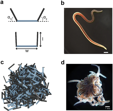
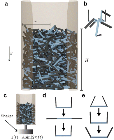
To test the material properties of non-convex granular aggregates, we constructed a three-link robot in simulation Fig. 1(a and c) and compared the dynamics of entangling robots to the entangled collective behavior demonstrated by entangling collectives of blackworms Fig. 1(b and d). Additionally, using stress–strain tests on an entangled chain of robotic smarticles, we report various properties related to their emergent auxeticity (see ESI† section).2.1 Multibody simulation of smarticles
We developed a 3D multibody simulated model of many u-shaped three-link smart active particles, henceforth called “smarticles”. The simulated smarticles (Fig. 1(a)), are capable of actuating their outer links in response to stimuli but we do not utilize their “smart”, e.g. closed-loop sensing and responding capabilities in this study. The smarticle's form was inspired by Purcell's three-link swimmer43,44 and the dynamic properties of these shape changing active system have been studied in 2D (planar) experiment13,45 in and the geometry and dimensions were inspired by previous work from Gravish et al.10 Two outer links (or barbs) were connected to a middle segment by rotational actuators, making the smarticle a planar system with two degrees-of-freedom. The middle link was of width w = 1.17 cm and the barbs are of length l = [0 − 1.1]w (all simulation parameters are shown in Table 1). The multibody simulation was implemented using ProjectChrono,46,47 an open-source physics dynamics engine.| Parameter | Value |
|---|---|
| w | 1.17 cm |
| dt | 2 × 10⁻⁴ s |
| f | 30 Hz |
| Γ | 2 |
| ρ | 7850 kg m−3 |
| τ | 1 |
| ω | 6 rads s−1 |
| t 1 | 1.27 mm |
| t 2 | 0.5 mm |
| μ particle–wall | 0.4 |
| μ particle–particle | 0.4 |
| r | 2w |
| H T(ti) | 20t2 |
| H B(ti) | 10t2 |
Since smarticles can actuate their barbs to specific positions, each motor was velocity-controlled with a maximum allowable torque. Smarticle barbs were controlled to move with an angular velocity of ω = 6 rad s−1. The maximum allowable torque, τmax, was set to the torque required to lift a mass equivalent to a smarticle of l/w = 0.7, a distance w away from the actuator's axis. For τi ≥ τmax, the ith barb's movement was halted until the first time step where the condition τi < τmax was satisfied.
Each simulation consisted of three phases: a deposition phase Fig. 2(a), an activity phase, and a final testing phase for certain simulations. A relaxation period was added between each activity phase (when energy is added to the system) and testing phase. During this period, no activity was added to the system. We chose a relaxation period of 0.5 seconds, which was determined to provide sufficient amount of time for the system to settle. In the deposition phase, smarticles were given a random initial and rotation position, and were released to fall, by gravity, into a hollow cylinder of radius r = 2w. All barbs were held static at the position: (α1, α2) = (π/2, π/2) during this phase (see Fig. 1(a)). The activity phase began once all smarticles were deposited in the system. This phase was responsible for changing the material properties of the collective by affecting the average entanglement between smarticles Fig. 2(a and b). We define entanglement as the interpenetration of concave particles through a plane defined by the barbs on a smarticle.
In the activity phase, activity was added to the system in one of three ways, where each active procedure represented a categorically different type of motion: an external sinusoidal oscillation of the confining cylinder (“externally-oscillated”) Fig. 2(c), a single cycle of a large angular change of each particles' barbs (“shape-change”) Fig. 2(d), and finally, many in-phase small amplitude oscillations of each particles' barbs (“internally-oscillated”) Fig. 2(e). In the externally-oscillated procedure, the container was shaken with a peak acceleration Γ = 2 (in units of gravitational acceleration g) at f = 30 Hz and oscillated for 20 s (600 cycles) Fig. 2(c). The shape-change procedure represented large amplitude movements. In shape-change simulations, the barbs were given 1.5 s to actuate from (α1, α2) = (90°, 90°) to (α1, α2) = (0°, 0°), then another 1.5 s to actuate back to their original position (α1, α2) = (90°, 90°) (Fig. 2(d)). The internally-oscillated procedure represents small amplitude vibrational motion. The arc length travelled by the barbs' tips, for a given degree amplitude θ, was constant for all l/w in the internally-oscillated trials. The distance travelled by the barb's tips was kept constant for all l/w. The travel distance was set to be equivalent to the arc length traversed by an arm of length l with l/w = 0.7. The arm travelled by an angle θ = ±[5°, 30°]/2 (Fig. 2(e)) from the original (90°, 90°) position. This ensured that the arc length traced by the barb tip was equal, for all l/w, at a single oscillation amplitude θ.
The activity phase in the internally-oscillated procedure lasted 5 s before any subsequent procedures began. These various methods were used to encourage higher entanglement than was achieved in deposition. Following the activity phase was a testing phase.
In the testing phase, we performed “casting” and “sculpting” tests, which examined qualitative material properties of a collective after smarticle activations. After smarticles were deposited in a container of a certain shape and activated, the container walls were removed for testing (see ESI† Video S1).
In all the simulations, the range of aspect ratios tested in the smarticle system for all procedures was l/w ∈ [0.4,1.1]. For the internally-oscillated system, the oscillation amplitude was θ ∈ [5°, 30°].
2.2 Comparing multibody simulations to nature
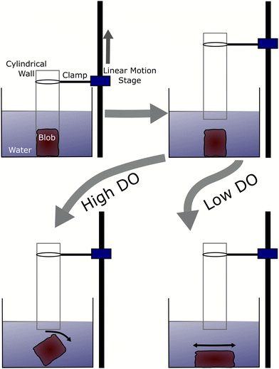
We compared smarticle simulations to emergent physically-entangled behaviors demonstrated by blackworms. Outside of their natural granular or detritivorous habitat, these worms entangle together forming a highly dense worm blob (Fig. 1d) due to their thigmotactic behavior.48,49 Furthermore, depending on the oxygenation of their surrounding, blackworms can disentangle their tails from the collective and lift it up to supplement respiration in hypoxic, or low dissolved oxygen (DO), conditions.48,49 By altering the dissolved oxygen in a container, we can vary the entanglement strength displayed by a worm blob and observe its emergent dynamics. We define low and high DO as <2 mg L−1 and >8 mg L−1, respectively.3 Results and discussion
3.1 Simulation
We test how ϕ evolves for a collective undergoing external oscillation. Fig. 3(a) shows how ϕ evolved over time for different aspect ratios. As l/w decreases, the initial and final volume fraction, ϕ0 and ϕf respectively, increase. The inset in Fig. 3(a) shows l/w = 1.1 with t ∈ [12.375s, 12.625s], the oscillations in the inset are consistent with the applied oscillation frequency f = 30 Hz. Further, the rate at which ϕ increases as a function of l/w, is faster than linear, which is illustrated in Fig. 3(b). This is true for both the ϕ0 and ϕf. Fig. 3(b) shows a comparison of our simulation to results from a similar experimental system.10 Both ϕ0 and ϕf are monotonically decreasing functions of l/w. Our simulation results agree with the experimental system.
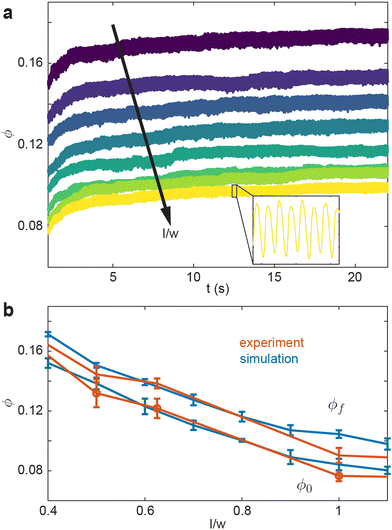 | ||
| Fig. 3 Volume fraction evolution as a function of smarticle aspect ratio under external oscillatory forcing. (a) ϕ vs. time for various smarticles aspect ratios l/w ∈ [0.4,1.1] l/w ∈ [0.4,1.1] The inset is a zoomed in version of the data from l/w = 1.1 over a 0.25 s domain. (b) ϕ as a function of aspect ratio in experiment (orange) and simulation (blue). The bottom two curves represent the volume fraction before activity was added to the system ϕ0 in both simulation and experiment. The top two curves are the final volume fraction after external forcing ϕf. The orange curves were taken from data used in Gravish et al.10 | ||
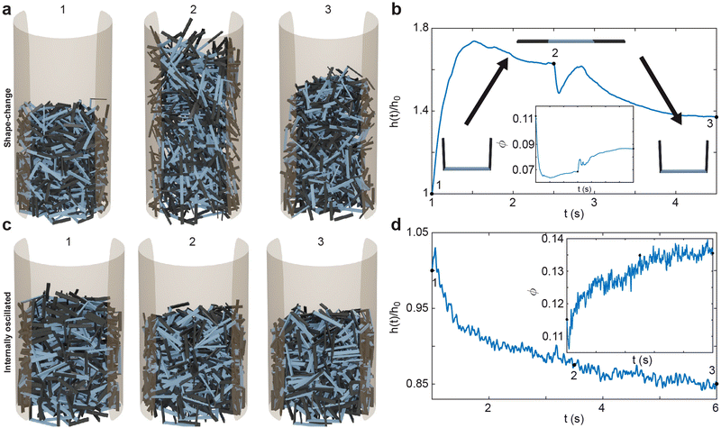
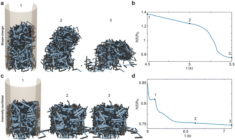
The smarticle collective's height never returns to the initial height of h0, despite all constituents returning to their original shape after deposition. Since the number of smarticles does not change during a trial, the change in height suggests that the procedure has changed the macroscopic state. After performing the shape-change procedure, the smarticles were not as well-molded or sculpted to the container as before. This suggests that the shape-change activation tends to force the smarticles away from the container wall as they transition back to the final u-shape. This inwardly-directed movement during the activation indicates an inwardly pointing attractive force. We suspect that the origin of the force arises from the geometry of the smarticle's final shape, as well as from the confining walls. The now-excluded volume between the outer walls and curled smarticles drives the collective upwards, increasing its height after the initial drop after point 2 in Fig. 4(b).
The internally-oscillated smarticles affect the collective differently than the shape-change procedure, Fig. 4(c). As smarticles vibrate their barbs, each unit interact with their neighbors causing them to rotate and displace. This allows particles to move into empty spaces that may exist between neighbors. Since gravitational force points downward, most rearrangement tends to lead to the compaction of particles until an equivalent random close packing (RCP) value for the smarticle shape is approached.53,54 As smarticles fill voids, the collective tends to decrease in height and becomes denser. This increase in density indicates that the smarticle collective is molding more closely to the container boundary; thereby producing a final height of less than h0. In Fig. 4(d), we see that the majority of the compaction happens rapidly, in fact, the first 50% of the final compaction is reached after only ≈12% of the total activation time has elapsed.
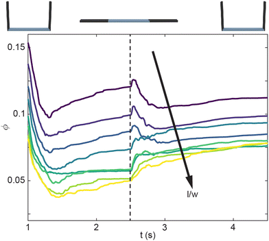
Next, we look at how the geometry of the smarticles, as well as the amplitude of their movements, affects the packing state of each system. In the shape-change procedure, ϕ generally decreases as the aspect ratio increases (Fig. 5). Past l/w > 0.6, ϕ monotonically increases (rather than increasing for a short time then decreases). This behavior suggests the existence of a critical packing fraction, which likely exists between 0.7 < l/wcrit < 0.6.
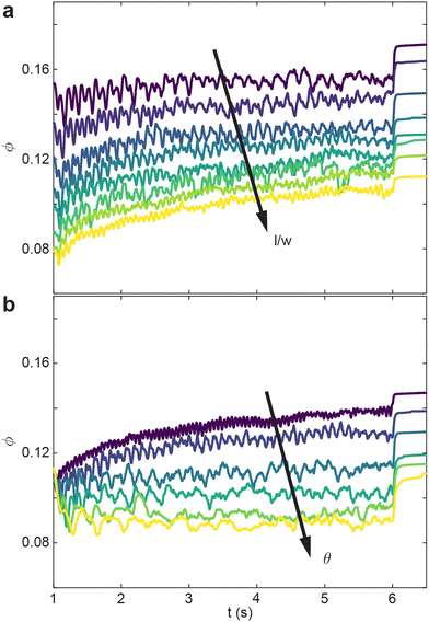
The internally-oscillated procedure is affected similarly as the shape-change with regards to the aspect ratio l/w. In Fig. 6(a)θ = 10° is held constant, and similar with the shape-change procedure, ϕ of the internally-oscillated procedure decreases with increasing l/w. Δϕ = ϕf − ϕ0 also increases with increasing l/w. For a given smarticle in a collective, as the barbs increase in length, the number of neighboring units the smarticle interacts with will generally increase. During internally-activated procedures, longer barbs tend to create more overall motion in, and of, the collective. The increased motion, or collective “temperature”, tends to rearrange smarticles when volume is available. For the simulation, at a given θ, the arc length travelled by barb tips is constant for all l/w. This explains why the oscillations in ϕ tend to decrease as l/w the oscillation frequency increases as l/w increases.
Given a constant l/w = 0.7, in Fig. 6(b) we vary oscillation amplitude θ. We find that ϕ decreases as θ increases. As oscillation amplitude increases, larger vacancies form among neighbors, but the larger θ hinders flow into the temporary vacancies made by the barb motion. While θ increases, Δϕ decreases as well.
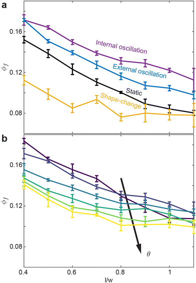
Finally, we compare how ϕf varies with l/w for all activation procedures (Fig. 7(a and b)). The internally-oscillated procedure tends to pack more densely, whereas the shape-change procedure tends to pack the least Fig. 7(a). Among various oscillation amplitudes, lower amplitudes tend to pack more tightly than larger amplitudes Fig. 7(b). Indeed, the largest amplitude shows only a marginal increase in ϕ compared to the static system, where there is no smarticle activation after the deposition phase (Fig. 7(a)).
 | (1) |
 | (2) |
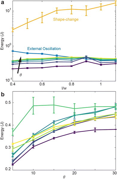
Fig. 8(a) reveals that the shape-change procedure requires the most energy to perform, regardless of the aspect ratio. Indeed, shape-change required greater than an order of magnitude increase in energy compared to the internally-oscillated procedure, which required generally the lowest amount of energy. Plotted in Fig. 8(a) are all oscillation amplitudes in the internally-oscillated procedure. As θ increases, the energy required to perform the procedure also increase. Similarly, the energy to perform the procedure increases with l/w with the exception of local maxima at l/w = 0.9.
Plotted in Fig. 8(b) is the energy as a function of oscillation amplitude for various aspect ratios. Apart from l/w = 0.9, energy tends to increase with amplitude. Next, given each procedure's energy expenditure, we measure how the average entanglement in the collective varies for each procedure.
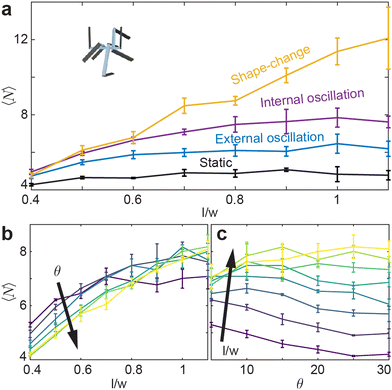
While entanglement is largely independent of aspect ratio in the static, or inactive, procedure, it is more dependent on aspect ratio in the active procedures Fig. 9(a). Apart from the shape-change procedure, all other active procedures tend to display a maximum of l/w ≈ 1.0. As l/w increases, the barbs increase in length, thereby requiring more movement between two entangled components to become disentangled. Larger barbs make disentangling more difficult; this is true to an even greater degree in confined systems. Although smarticles with larger l/w will remain entangled more readily, they are less likely to become entangled.10 The shape-change system does not have this issue: the entangling action happens during the straight to u-shape transition. During this time, a barb's length does not act to restrict a new entanglement from arising, as the smarticle shape starts from a convex (straight) shape. Therefore, larger values of l/w increase the likelihood of entanglements happening in the shape-change system, as the area defining interpenetration is larger.
Now we examine how θ and l/w affect 〈N〉 in the internally-oscillated system. In these trials, we measured entanglements over θ = [5°–30°] for all l/w in Fig. 9(b). At l/w < 0.7, as θ increases, the number of entanglements decrease. At larger l/w, 〈N〉 becomes approximately independent of l/w. The functional form of entanglement, as a function of amplitude, changes as aspect ratio increase. At low aspect ratios, l/w = [0.4–0.5], the curve is monotonically decreasing. However, as l/w increases, the curve is no longer monotonic: a peak forms between θ = [10°–15°]. As barbs increase in length, the location of the peak also increase. Furthermore, the peak's relative amplitude to the rest of the curve also increases. We posit that this is related to the argument stated before: at low l/w, there is an increased likelihood to both entangle and to disentangle; therefore, the barbs can break the entanglements faster than new ones are generated. However, if the arms are longer, the same arc length travelled will not tend to disentangle an existing connection. The amplitude, as well as the energy threshold that is necessary to break pre-existing bonds, is larger.
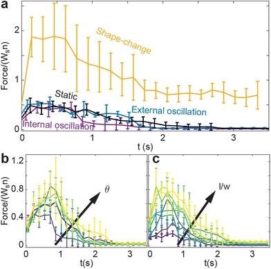
The static system (not shown in the energy plot) has zero energy input, and the 〈N〉 is the lowest for all aspect ratios measured. The internally- and externally-oscillated procedures have similar energy inputs; although the internally-driven system is slightly lower. In the internally-driven system, however, the number of entanglements measured after the deposition phase is noticeably larger. Aside from requiring different amounts of energy to prepare each procedure, each procedure also tends to impart different collective attributes. Since entangling allows a collective to support tensile loads, next we test how well each procedure allows a collective to maintain its structural integrity, to both sculpt to containers of different shapes (“casts”), and keep its shape after the cast is removed.
After the deposition and activation of smarticle collectives, in Fig. 10(a–d) we removed the outer boundary and examined how the unconfined collective settles. The shape-change system, Fig. 10(a and b), does not break apart nor do the particles on the periphery disengage from the collective: the collective holds firmly together. Since shape-change narrows the base and increases the height, this procedure tends to produce less stable structures. Indeed, in the illustrated example, the structure falls onto its side in Fig. 10(a.3). We define this behavior as “toppling” since the unstable collective is unable to maintain its vertical position and falls onto its side. The internally-oscillated system reacts differently than the shape-change system when the confinement is removed. Since the internally-oscillated procedure increases in ϕ, decreasing the height of the collective while maintaining its width, the stability of the final collective is improved compared to the initial state after deposition. However, because the amount of entanglement was lower than in the shape-change procedure after the walls were removed, some smarticles on the outer edge slough off as they are not entangled tightly with neighbors in the structure. We define this behavior as “melting” since the structure dissolves as smarticles are not firmly entangled with one another, causing detachment from the collective. In the next section, we will examine in more detail structure formation using these two procedures.
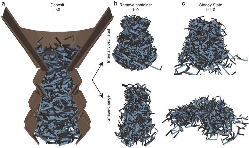 | ||
| Fig. 11 Smarticle aggregate casting and sculpting capabilities. (a) Particles are deposited in in a three-tiered system at l/w = 0.8 with each tier smaller than the one below. In (b), after the activation state has occurred, (top is internally-oscillated at θ = 10° and bottom is the shape-change) the outer walls are removed. (c) The piles one second after the container is removed for the internally-oscillated (top) and shape-change (bottom) procedures procedures.(Movie S1, ESI†) | ||
While activation procedures tend to compact a collection, they do so in distinct ways; these distinctions lead to the macroscopic differences visible in the remaining structure after the container is removed. Internal oscillation imparts the fluid-like property of being able to fill its container, and the activity tends to help smarticles flow into voids. While the container is filled more completely (as shown by the increase in ϕ), this does not imply increases in entanglement. This is evident in Fig. 11(b) in the instant the walls were removed. The system has the shape of the container but, shortly afterward, the overhangs tend to fall apart. For the shape-change procedure, while the collective becomes more compact, it is not due to an improved container space usage. The walls serve to give a basic conical shape, but the particle structure consolidates inward and grows upward, rather than outward. Previously, we showed how we can affect the number of entanglements by using different procedures (Fig. 9). Shape-change produces greater entanglement allowing particles to stay together more readily, but it does not sculpt to the container as easily as the internally-oscillated procedure. After the activation procedure completion in the shape-change procedure, the system exhibits properties of a hardened structure, whereas the internally-oscillated procedure tends to flow apart and is comparably softer, eroding at its surface after the removal of the walls. We find analogies between the shape-change and internal oscillation procedure and rapid and slow quenching in metallic systems. In metals, rapid temperature reduction in the quenching process tends to leave a metal harder but more brittle, with a great deal of internal stress. Conversely, a slowly quenched metal will see a reduction in the internal stress as well as becoming softer.50 These effects are further supported through quantitative tests in the simulated fracture tests and in the biological experiments performed in the next sections.
To investigate how material properties are affected, we performed various fracture tests. In Fig. 13(a) for the three procedures, the peak force output, which we define as fracture force, and the entanglements (Fig. 9(a)) do not keep the same ordering. The shape-change system shows the highest peak force output, whereas internal oscillation displays the least amount of tensile strength. There is agreement between force generated as a function of internal oscillation as shown in Fig. 13(b) and in the number of entanglements for a given oscillation amplitude as shown in Fig. 9(b). Using this simulated system, we found a connection between tensile strength and number of entanglements. We measure tensile strength through the fracture test, and found the system which had highest strength was the shape-change system, which also exhibited the largest number of average entanglements. Next, we compare emergent properties that arises from simulations to physically-entangled collective dynamics found in biology.
3.2 Biological Experiment
Inspired by the results from simulations, we conducted experiments using an analogous entangled system found in nature. Similar to how smarticles display the metallurgical dynamics of annealing, worm blobs can emergently display a few of these behaviors from their entanglement. Of course, we note that in contrast to smarticles, blackworms are highly dynamic and flexible with aspect ratios >40 and can generate thrust using muscles across its body length.32,55,56 Additionally, a worm can display a range of length as it extends and contracts its body.As an analogy to states achieved upon shape-changes, worms blobs can display either very high or very low entanglement in steady state environmental parameters. Similar to the smarticle simulations, low levels of entanglement occur when worms are extended (Fig. 1(b)) similar to when the barbs travel π/2 outwards (Fig. 2(d)). However, when transitioning between levels of environmental parameters, worms can reversibly vary their activity levels and change their level of entanglement, an analogy for internal oscillations. For example, according to Tuazon, et al., worm blobs show less activity and less exposed structural surface area in high DO (>8 mg L−1) as opposed to hypoxic conditions (<2 mg L−1).42 Furthermore, worm blobs in high DO shows higher internal mechanical stress, which was demonstrated by lifting worm blobs using a 3D-printed serrated endpiece in two extreme levels of DO. Additionally, according to Ozkan-Aydin, et al.,4 a highly entangled, “solid-like” blob was observed in lower temperatures (T < 25 °C). However, when exposed to higher temperatures T > 25 °C, the blob slowly disentangled into a “fluid-like” aggregate which demonstrates that higher temperature leads to higher internal oscillations, followed by full disentanglement. In short, worm blobs in low temperatures and/or in high DO environments tend to display solid-like structural properties and vice versa.
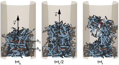
 , of the blob is plotted as a function of time in (Fig. 14(b)). As individual worms move to obtain oxygen, the height of centroid monotonically decreases.
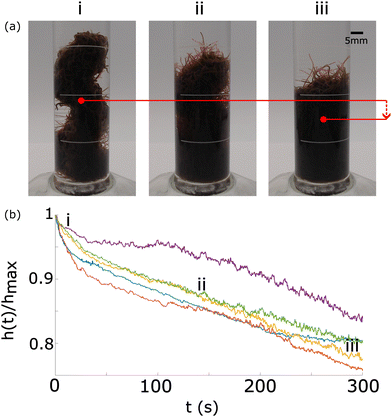 | ||
Fig. 14 Evolution of a worm blob from a rigid structure at high concentration of DO to a loosely entangled state in a lower concentration of DO. (a) The red dot depicts the centroid, which move downwards over time as DO is consumed by the worms. Blackworms supplement respiration by disentangling their posterior segments and raising it upwards, emergently relaxing the structure. (b) The normalized height of the blob's centroid,  , plotted as a function of time. Numbers in the time series correspond to the snapshots shown in (a). n = 5 trials (Movie S2, ESI†). , plotted as a function of time. Numbers in the time series correspond to the snapshots shown in (a). n = 5 trials (Movie S2, ESI†). | ||
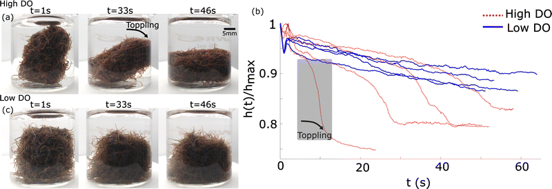 | ||
Fig. 16 Tumbling worm blobs. Timelapse of a tumbling worm blob (∼8 g) at three instances when present in a (a) high DO and a (b) low DO environment. (c) Timeseries of the normalized height of the blob's centroid,  , over time. T = 0 s represents the instance where the inside wall was lifted outside of the water in high DO (blue dotted curves). The gray shaded region indicates the large drop in centroid height when toppling occured for one trial in high DO conditions. n= 4 trials for each DO levels. (Movie S3, ESI†) , over time. T = 0 s represents the instance where the inside wall was lifted outside of the water in high DO (blue dotted curves). The gray shaded region indicates the large drop in centroid height when toppling occured for one trial in high DO conditions. n= 4 trials for each DO levels. (Movie S3, ESI†) | ||
In low DO concentration, the blob is more “relaxed” and exhibits significantly less rigidity. Once the wall is removed, the worm ensemble slowly adjusts to the shape of the container (Fig. 16(c)). The corresponding time series for the normalized height of the blob's projected centroid is plotted in Fig. 16(b).
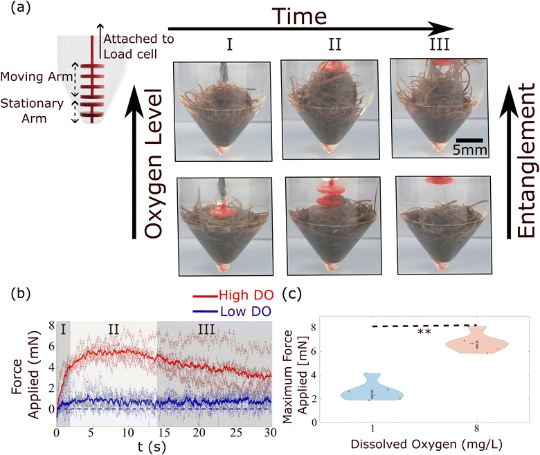
In high DO, worm blobs resist the removal of the 3D-printed piece. The timeseries of the force applied on the load cell in the two DO conditions is plotted in Fig. 17(b). This plot shows that worm blobs applies significantly greater amount of force under tensile stress in a high DO (high entanglement) environment. The maximum force applied by the blobs from 6 repetitions of this experiment is presented in Fig. 17(c) for two different DO concentrations. We find that the maximum force applied under tensile stress is significantly different (p < 0.01) for the case of high DO compared to that of low DO environments.
4 Conclusions
We performed, to our knowledge, the first study of time-dependent material-properties of soft amorphous entangled matter through numerical simulations and in living systems. Despite the seemingly complex interactions which comprise the material properties of a collective, we found that in simulation the amount of entanglement, which encodes much of the material properties, is controllable. Building upon previous studies of entangleable materials, we found that fracture force increased with the degree of entanglement in a simulation. Next, we compared our simulations to the physically-entangled collective behavior of blackworms. By exposing the animals to varying DO conditions, worm blobs displayed both solid- and fluid-like structural dynamics. We found that worms in high DO conditions interweave strongly with one another and exert significantly more force than in low DO conditions.In the future, we envision an adaptable material capable of maximal or minimal entanglement in response to stimuli (i.e. fire ants’ raft formations in the presence of flooding3,29). To achieve this, it is important to consider factors affecting the material properties and behavior, including the orientation of the particles. Thus, we advocate investigation of the presence of biaxial nematic, cholesteric, or twist-bend properties of the smarticles, which may have a significant impact on the overall entanglement of the system. With this understanding, the entanglement response of the material can be spread through the collective ‘‘organically’’, or via local communication, allowing for greater control and efficiency in adjusting its level of entanglement.57 We posit that insights from our study could lead to barb activation procedures which optimize energy. Due to improvements in computational modeling and simulation, material science, and design engineering in the field of rheology over the last century, there has been an explosion in the number of goods with designed material properties based on their purpose: from detergents, to plastics, to hydrophobic clothing.58 We posit that by improving our understanding of the emergent collective dynamics of mutable active particles, we can take steps towards creating adaptive, shape-shifting and task-capable soft, supermaterials.59
Author contributions
W. S. designed and carried out the smarticles simulations and experiments, analyzed, and interpreted the results. H. T. and I. T. observed, designed, and carried out the biological experiments, analyzed, and interpreted the results. D. I. G. and M. S. B. reviewed the design and execution of experiments, the data analysis, the interpretations, and the manuscript. All authors contributed to writing the manuscript.Conflicts of interest
There are no conflicts to declare.Acknowledgements
H. T. acknowledges funding support from the NSF graduate research fellowship program (GRFP) and Georgia Tech's President's Fellowship. D. I. G. acknowledges funding support from ARO MURI award (W911NF-19-1-023), NSF Physics of Living Systems Grant (PHY-1205878), and the Dunn Family Professorship award. M. S. B. acknowledges funding support from NIH Grant R35GM142588; NSF Grants MCB-1817334; CMMI-2218382; CAREER IOS-1941933; and the Open Philanthropy Project. We thank members of the Bhamla lab and Goldman lab for useful discussions. We especially want thank Akash Vardhan for experimental assistance, Dana Randall, Andréa W. Richa, and Paul Umbanhowar for helpful discussions. Finally, we thank Dr Prateek Seghal for assisting with the image analysis of the biological experiment.References
- D. Hu, S. Phonekeo, E. Altshuler and F. Brochard-Wyart, Eur. Phys. J.: Spec. Top., 2016, 225, 629–649 Search PubMed.
- C. R. Reid, T. Latty, A. Dussutour and M. Beekman, Proc. Natl. Acad. Sci U. S. A., 2012, 109, 17490–17494 CrossRef CAS PubMed.
- N. J. Mlot, C. A. Tovey and D. L. Hu, Proc. Natl. Acad. Sci U. S. A., 2011, 108, 7669–7673 CrossRef CAS PubMed.
- Y. Ozkan-Aydin, D. I. Goldman and M. S. Bhamla, Proc. Natl. Acad. Sci U. S. A., 2021, 118, e2010542118 CrossRef CAS PubMed.
- D. Blackiston, E. Lederer, S. Kriegman, S. Garnier, J. Bongard and M. Levin, Sci. Robot., 2021, 6, eabf1571 CrossRef PubMed.
- S. Kriegman, D. Blackiston, M. Levin and J. Bongard, Proc. Natl. Acad. Sci U. S. A., 2020, 117, 1853–1859 CrossRef CAS PubMed.
- S. Dumont and M. Prakash, Mol. Biol. Cell, 2014, 25, 3461–3465 CrossRef PubMed.
- F. Ndlec, T. Surrey, A. C. Maggs and S. Leibler, Nature, 1997, 389, 305–308 CrossRef PubMed.
- T. Surrey, F. Nédélec, S. Leibler and E. Karsenti, Science, 2001, 292, 1167–1171 CrossRef CAS PubMed.
- N. Gravish, S. V. Franklin, D. L. Hu and D. I. Goldman, Phys. Rev. Lett., 2012, 108, 208001 CrossRef PubMed.
- J.-F. Boudet, J. Lintuvuori, C. Lacouture, T. Barois, A. Deblais, K. Xie, S. Cassagnere, B. Tregon, D. Brückner and J.-C. Baret, et al. , Sci. Robot., 2021, 6, eabd0272 CrossRef PubMed.
- S. Li, R. Batra, D. Brown, H.-D. Chang, N. Ranganathan, C. Hoberman, D. Rus and H. Lipson, Nature, 2019, 567, 361–365 CrossRef CAS PubMed.
- W. Savoie, T. A. Berrueta, Z. Jackson, A. Pervan, R. Warkentin, S. Li, T. D. Murphey, K. Wiesenfeld and D. I. Goldman, Sci. Robot., 2019, 4, eaax4316 CrossRef PubMed.
- P. Anderson, More is different Science l77, 393–399 (1972), CV Negoita, Fuzzy Systems, 1980.
- C. H. Hsueh and W. C. J. Wei, J. Appl. Phys., 2010, 107, 024905 CrossRef.
- E. Brown, H. Zhang, N. A. Forman, B. W. Maynor, D. E. Betts, J. M. DeSimone and H. M. Jaeger, Phys. Rev. E: Stat., Nonlinear, Soft Matter Phys., 2011, 84, 031408 CrossRef PubMed.
- R. G. Egres and N. J. Wagner, J. Rheol., 2005, 49, 719–746 CrossRef CAS.
- R. C. Kramb and C. F. Zukoski, J. Rheol., 2011, 55, 1069–1084 CrossRef.
- K. A. Murphy, A. K. MacKeith, L. K. Roth and H. M. Jaeger, Granular Matter, 2019, 21, 1–6 CrossRef.
- A. Z. Nelson, K. S. Schweizer, B. M. Rauzan, R. G. Nuzzo, J. Vermant and R. H. Ewoldt, Curr. Opin. Solid State Mater. Sci., 2019, 100758 CrossRef CAS.
- W. Man, A. Donev, F. H. Stillinger, M. T. Sullivan, W. B. Russel, D. Heeger, S. Inati, S. Torquato and P. M. Chaikin, Phys. Rev. Lett., 2005, 94, 198001 CrossRef PubMed.
- K. Desmond and S. V. Franklin, Phys. Rev. E: Stat., Nonlinear, Soft Matter Phys., 2006, 73, 031306 CrossRef CAS PubMed.
- M. Z. Miskin and H. M. Jaeger, Soft Matter, 2014, 10, 3708–3715 RSC.
- M. Trepanier and S. V. Franklin, Phys. Rev. E: Stat., Nonlinear, Soft Matter Phys., 2010, 82, 011308 CrossRef CAS PubMed.
- J. Blouwolff and S. Fraden, EPL, 2006, 76, 1095–1101 CrossRef CAS.
- M. Z. Miskin and H. M. Jaeger, Nat. Mater., 2013, 12, 326 CrossRef CAS PubMed.
- M. L. Gardel, M. T. Valentine, J. C. Crocker, A. R. Bausch and D. A. Weitz, Phys. Rev. Lett., 2003, 91, 158302 CrossRef CAS PubMed.
- P. C. Foster, N. J. Mlot, A. Lin and D. L. Hu, J. Exp. Biol., 2014, 217, 2089–2100 CrossRef PubMed.
- N. J. Mlot, C. Tovey and D. L. Hu, Commun. Integr. Biol., 2012, 5, 590–597 CrossRef PubMed.
- T. McLeish, Phys. Today, 2008, 61, 40–45 CrossRef CAS.
- O. Lieleg, K. M. Schmoller, C. J. Cyron, Y. Luan, W. A. Wall and A. R. Bausch, Soft Matter, 2009, 5, 1796–1803 RSC.
- C. Nguyen, Y. Ozkan-Aydin, H. Tuazon, D. I. Goldman, M. S. Bhamla and O. Peleg, Front. Phys., 2021, 9, 1–12 Search PubMed.
- A. Deblais, A. Maggs, D. Bonn and S. Woutersen, Phys. Rev. Lett., 2020, 124, 188002 CrossRef CAS PubMed.
- A. Deblais, S. Woutersen and D. Bonn, Phys. Rev. Lett., 2020, 124, 208006 CrossRef CAS PubMed.
- C. M. Henein and T. White, Phys. A, 2007, 373, 694–712 CrossRef.
- A. Garcimartn, J. Pastor, L. Ferrer, J. Ramos, C. Martn-Gómez and I. Zuriguel, Phys. Rev. E: Stat., Nonlinear, Soft Matter Phys., 2015, 91, 022808 CrossRef PubMed.
- X. Zheng, T. Zhong and M. Liu, Build. Environ., 2009, 44, 437–445 CrossRef.
- N. Michael, C. Belta and V. Kumar, Proceedings 2006 IEEE International Conference on Robotics and Automation, 2006. ICRA 2006., 2006, pp. 964-969.
- D. H. Kelley and N. T. Ouellette, Sci. Rep., 2013, 3, 1073 CrossRef CAS PubMed.
- W. Savoie, T. A. Berrueta, Z. Jackson, A. Pervan, R. Warkentin, S. Li, T. D. Murphey, K. Wiesenfeld and D. I. Goldman, Sci. Robot., 2019, 4, eaax4316 CrossRef PubMed.
- W. Savoie, S. Cannon, J. J. Daymude, R. Warkentin, S. Li, A. W. Richa, D. Randall and D. I. Goldman, Artif. Life Robot., 2018, 23, 459–468 CrossRef.
- H. Tuazon, E. Kaufman, D. I. Goldman and M. S. Bhamla, Integr. Comp. Biol., 2022, 62(4), 890–896 CrossRef PubMed.
- E. M. Purcell, Am. J. Phys., 1977, 45, 3–11 CrossRef.
- R. L. Hatton, Y. Ding, H. Choset and D. I. Goldman, Phys. Rev. Lett., 2013, 110, 078101 CrossRef PubMed.
- P. Chvykov, T. A. Berrueta, A. Vardhan, W. Savoie, A. Samland, T. D. Murphey, K. Wiesenfeld, D. I. Goldman and J. L. England, Science, 2021, 371(6524), 90–95 CrossRef CAS PubMed.
- P. Chrono, Chrono: An Open Source Framework for the Physics-Based Simulation of Dynamic Systems, https://projectchrono.org, 2019, Accessed: 2019-01-17.
- A. Tasora, R. Serban, H. Mazhar, A. Pazouki, D. Melanz, J. Fleischmann, M. Taylor, H. Sugiyama and D. Negrut, International Conference on High Performance Computing in Science and Engineering, 2015, pp. 19-49.
- T. Timm and P. J. Martin, Clitellata: Oligochaeta, Elsevier, 2015, pp. 529–549 Search PubMed.
- C. D. Drewes, J. Iowa Acad. Sci., 1990, 97, 112–114 Search PubMed.
- W. Callister, Materials science and engineering: an introduction, Wiley, Hoboken, NJ, 2014 Search PubMed.
- N. Gravish, P. B. Umbanhowar and D. I. Goldman, Phys. Rev. E: Stat., Nonlinear, Soft Matter Phys., 2014, 89, 042202 CrossRef PubMed.
- S. Agarwal, C. Senatore, T. Zhang, M. Kingsbury, K. Iagnemma, D. I. Goldman and K. Kamrin, J. Terramechanics, 2019, 85, 1–14 CrossRef.
- G. Scott and D. Kilgour, J. Phys. D: Appl. Phys., 1969, 2, 863 CrossRef.
- B. Andreotti, Y. Forterre and O. Pouliquen, Granular media: between fluid and solid, Cambridge University Press, 2013 Search PubMed.
- C. D. Drewes and C. R. Fourtner, Biol. Bull., 1989, 177, 363–371 CrossRef.
- C. D. Drewes, Hydrobiologia, 1999, 406, 263–269 CrossRef.
- N. A. Kasian, L. N. Lisetski and I. A. Gvozdovskyy, Liq. Cryst., 2022, 49, 142–152 CrossRef CAS.
- H. A. Barnes, J. F. Hutton and K. Walters, An introduction to rheology, Elsevier, 1989 Search PubMed.
- M. A. McEvoy and N. Correll, Science, 2015, 347, 1261689 CrossRef CAS PubMed.
Footnotes |
| † Electronic supplementary information (ESI) available. See DOI: https://doi.org/10.1039/d2sm01573k |
| ‡ These authors contributed equally to this work. |
| This journal is © The Royal Society of Chemistry 2023 |

![[thin space (1/6-em)]](https://www.rsc.org/images/entities/i_char_2009.gif)
