Stabilizing a zinc anode via a tunable covalent organic framework-based solid electrolyte interphase†
Vipada
Aupama
 a,
Wathanyu
Kao-ian
 a,
Jinnawat
Sangsawang
 a,
Gopalakrishnan
Mohan
 a,
Suttipong
Wannapaiboon
 b,
Ahmad Azmin
Mohamad
 c,
Prasit
Pattananuwat
 de,
Chakrit
Sriprachuabwong
 f,
Wei-Ren
Liu
 g and
Soorathep
Kheawhom
 *aeh
*aeh
aDepartment of Chemical Engineering, Faculty of Engineering, Chulalongkorn University, Bangkok 10330, Thailand. E-mail: soorathep.k@chula.ac.th
bSynchrotron Light Research Institute, 111 University Avenue, Muang District, Nakhon Ratchasima 30000, Thailand
cSchool of Materials and Mineral Resources Engineering, Universiti Sains Malaysia, Nibong Tebal, Pulau Pinang 14300, Malaysia
dDepartment of Materials Science, Faculty of Science, Chulalongkorn University, Bangkok 10330, Thailand
eCenter of Excellence on Advanced Materials for Energy Storage, Chulalongkorn University, Bangkok 10330, Thailand
fNational Science and Technology Development Agency, Pathum Thani 12120, Thailand
gDepartment of Chemical Engineering, Research Center for Circular Economy, Chung Yuan Christian University, Chung Li, Taiwan, Republic of China
hBio-Circular-Green-Economy Technology & Engineering Center (BCGeTEC), Faculty of Engineering, Chulalongkorn University, Bangkok 10330, Thailand
First published on 17th April 2023
Abstract
Zinc (Zn) is an excellent material for use as an anode for rechargeable batteries in water-based electrolytes. Nevertheless, the high activity of water leads to Zn corrosion and hydrogen evolution, along with the formation of dendrites on the Zn surface during repeated charge–discharge (CD) cycles. To protect the Zn anode and limit parasitic side reactions, an artificial solid electrolyte interphase (ASEI) protective layer is an effective strategy. Herein, an ASEI made of a covalent organic framework (COFs: HqTp and BpTp) was fabricated on the surface of a Zn anode via Schiff base reactions of aldehyde and amine linkers. It is seen that COFs can regulate the Zn-ion flux, resulting in dendritic-free Zn. COFs can also mitigate the formation of an irreversible passive layer and the hydrogen evolution reaction (HER). Zn plating/stripping tests using a symmetrical cell suggest that HqTpCOF@Zn shows superior stability and greater coulombic efficiency (CE) compared to bare Zn. The full cell having COFs@Zn also displays much improved cyclability. As a result, the COF proves to be a promising ASEI material to enhance the stability of the Zn anode in aqueous media.
1. Introduction
Due to their cost-effectiveness, eco-friendliness, and intrinsic safety, aqueous zinc-ion batteries (AZIBs) are promising alternatives for grid-scale energy storage systems (ESSs).1,2 AZIBs store and convert energy by relocating Zn2+ between the cathode and the anode. As for the electrolyte, AZIBs typically employ an aqueous solution containing Zn2+ ions.3,4 Zn is an ideal anode material showing a high theoretical specific capacity (5851 mA h cm−3 and 820 mA h g−1), and a low redox potential (−0.76 V SHE).5 A metallic Zn anode can be used in conjunction with different cathode materials such as manganese oxides and vanadium oxides. In terms of performance and cyclability, a number of recently proposed AZIBs are thought to be very promising, specifically those with a specific capacity of more than 200 mA h g−1 and those with thousands of cycles of repeated charge–discharge capabilities. As yet, no ZIBs have been suggested for commercialization. According to the literature, there are many obstacles that restrict their practical application:(I) Hydrogen evolution reaction (HER): water is a protic solvent that can dissociate and provide protons (H+), thus the contribution of H+ upon charging is inevitable.6 As a result, the reduction of H+, producing H2 gas is regarded as a competitive reaction that lowers charging efficiency and increases pressure inside the battery cell.
(II) Formation of dendrites: dendritic growth is not a new problem in battery research, particularly in systems utilizing metallic anodes. Due to the non-uniform Zn-ion flux and electric field on the Zn anode, Zn dendrites can grow in AZIBs and induce short-circuits. In addition, operational parameters such as current density and areal capacity can influence the development of the Zn morphology and may even contribute to the emergence of dendritic structures during prolonged cycling.7
(III) Zn corrosion: the HER is different from the self-corrosion of Zn. Since protons (H+), which have a greater standard potential than Zn2+, are always present in aqueous mild-acid electrolytes, these protons can accept electrons from metallic Zn. Hence, H2 is generated so Zn corrodes, changing into Zn2+, and pressure builds up inside the cell. Such a result is possible even in an inactive state.8,9
(IV) Passivation: production of a passive layer, which impairs AZIB's performance over prolonged cycling, is of much concern. Zinc hydroxysulfate (ZHS) is discovered to be the primary passivation species in most commonly used electrolytes, i.e., aqueous ZnSO4 electrolytes. Because of the redox reaction, which includes the HER and H+ intercalation, ZHS can develop effectively at the specific location where H+ is consumed. In this situation, hydroxide ions (OH−) build up and combine with Zn2+ and SO42− to create ZHS, which adversely affects the performance of ZIBs.10
These problems have been addressed using different strategies, including electrolyte engineering, 3D structures of Zn anodes,11 modification of separators,12,13 and modification of surface.14 To regulate the Zn2+ flux, as well as decrease nucleation overpotential and suppress side reactions, the implementation of a solid electrolyte interphase on Zn anodes is seen to overcome this issue.15,16 To date, several artificial SEIs generated from metal–organic frameworks (MOFs)17 or covalent organic frameworks (COFs) have been investigated.15,18,19
Recently, COFs have been examined as potential candidates for ASEI materials because of their robust framework, perfectly tunable porous morphology, and fully active sites that are suitable channels for metal ion transfer (Li+, Na+, Mg2+, Zn2+, etc.), and also variable molecular configurations for improving electrochemical performance.20–24 These features have attractive applicability in batteries such as a host material in the cathode,23,25 a selective membrane as a separator,26–28 and a coating layer on the anode.15,19
Many reversible organic reactions have been used to synthesize COF structures, namely, trimerization of nitriles, boronic acid trimerization, boronate ester formation, and especially the Schiff base reaction, which can generate a stable form of the structure of COFs.29 The Schiff base reaction has been used for the synthesis of COFs whereby emerging crystalline porous materials linked via covalent bonding can be adjusted and modified for suitable and efficient use for any application.29 Banerjee et al.25 demonstrated that the β-ketonimine form of a COF was synthesized via condensation between an aldehyde linker and an amine linker in AZIBs. This COF provided excellent nucleophilic sites, which can bind with Zn2+ during the CD process. In addition, the interlayer interaction between Zn2+ along with C![[double bond, length as m-dash]](https://www.rsc.org/images/entities/char_e001.gif) O and N–H moieties from the neighboring layers brought about an improvement in the capacity. Both C
O and N–H moieties from the neighboring layers brought about an improvement in the capacity. Both C![[double bond, length as m-dash]](https://www.rsc.org/images/entities/char_e001.gif) O/Zn and N–H/Zn interactions are reversible in nature during the electrochemical redox process. Subsequently, Park et al.19 indicated that the functional group of C
O/Zn and N–H/Zn interactions are reversible in nature during the electrochemical redox process. Subsequently, Park et al.19 indicated that the functional group of C![[double bond, length as m-dash]](https://www.rsc.org/images/entities/char_e001.gif) O enabled a more uniform flux of Zn2+, facilitating uniform Zn nucleation and Zn deposition using a COF film as a coating layer on the Zn anode.
O enabled a more uniform flux of Zn2+, facilitating uniform Zn nucleation and Zn deposition using a COF film as a coating layer on the Zn anode.
Little research has been conducted using COFs as layers to form an ASEI on the Zn anode in ZIBs. In this work, we propose a COF structure, which provides a uniform flux of Zn2+ and limits Zn dendritic growth. The COF's layer consists of ketone (C![[double bond, length as m-dash]](https://www.rsc.org/images/entities/char_e001.gif) O) and imine (N–H) functional groups. The COF's layer is coated on the surface of the Zn anode as a protective layer between the Zn metal and the electrolyte. In Fig. 1, it is seen that the COF layers are generated by a condensed reaction between 2,4,6-triformylphloroglucinol (Tp), 2,5-diaminohydroquinone (Hq) and 4,4′-diaminobenzophenone (Bp). The two COFs (denoted as HqTpCOF and BpTpCOF) in this work provide suitable coating films, which have the following advantages: (1) C
O) and imine (N–H) functional groups. The COF's layer is coated on the surface of the Zn anode as a protective layer between the Zn metal and the electrolyte. In Fig. 1, it is seen that the COF layers are generated by a condensed reaction between 2,4,6-triformylphloroglucinol (Tp), 2,5-diaminohydroquinone (Hq) and 4,4′-diaminobenzophenone (Bp). The two COFs (denoted as HqTpCOF and BpTpCOF) in this work provide suitable coating films, which have the following advantages: (1) C![[double bond, length as m-dash]](https://www.rsc.org/images/entities/char_e001.gif) O and N–H in the structure of COF films can be coordinated with Zn2+, resulting in uniform Zn deposition on the surface of an anode to suppress dendritic growth, leading to cyclability. (2) A COF layer can reduce Zn2+ de-solvation energy, decreasing the Zn activation energy on the anode. (3) A COF film can suppress side reactions: Zn corrosion, HER, and ZHS that occur on the Zn anode.
O and N–H in the structure of COF films can be coordinated with Zn2+, resulting in uniform Zn deposition on the surface of an anode to suppress dendritic growth, leading to cyclability. (2) A COF layer can reduce Zn2+ de-solvation energy, decreasing the Zn activation energy on the anode. (3) A COF film can suppress side reactions: Zn corrosion, HER, and ZHS that occur on the Zn anode.
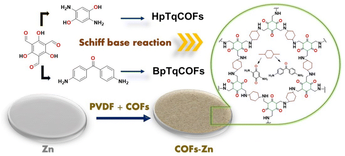 | ||
| Fig. 1 Scheme of structures and the preparation of COF layers: HqTpCOF and BpTpCOF as ASEIs on the Zn anode in AZIBs. | ||
2. Materials and methods
2.1. Materials
All chemicals and materials were commercially available and used as such without any further purification, including 2,4,6-triformylphloroglucinol (Tp) (>98.0% (GC), TCI) as an aldehyde linker, and 2,5-diaminohydroquinone dihydrochloride (Hq) (>97%, Alfa Aesar) and 4,4′-diaminobenzophenone (Bp) (>98.0% (T)(HPLC), TCI) as amine linkers. Mesitylene (98%, Sigma Aldrich), 1,4-dioxane (ACS Reagent, ≥99.0%, Sigma Aldrich), and dimethylformamide (DMF) (99.8+%, ACS Grade, Alfa Aesar) were used as solvents of reactions. Zinc sulfate heptahydrate (ZnSO4·7H2O) (≥99.0%, Kemaus) and manganese(II) sulfate monohydrate (MnSO4·xH2O) (≥99.0%, QREC) were used as metal salts for the battery electrolyte. Zinc foil (thickness 0.1 mm) and copper foil (thickness 0.05 mm) were used as substrates.2.2. Methods
![[thin space (1/6-em)]](https://www.rsc.org/images/entities/char_2009.gif) :
:![[thin space (1/6-em)]](https://www.rsc.org/images/entities/char_2009.gif) 1,4-dioxane
1,4-dioxane![[thin space (1/6-em)]](https://www.rsc.org/images/entities/char_2009.gif) :
:![[thin space (1/6-em)]](https://www.rsc.org/images/entities/char_2009.gif) dimethylformamide (1
dimethylformamide (1![[thin space (1/6-em)]](https://www.rsc.org/images/entities/char_2009.gif) :
:![[thin space (1/6-em)]](https://www.rsc.org/images/entities/char_2009.gif) 1
1![[thin space (1/6-em)]](https://www.rsc.org/images/entities/char_2009.gif) :
:![[thin space (1/6-em)]](https://www.rsc.org/images/entities/char_2009.gif) 2, v/v) for HqTpCOF. 4,4′-Diaminobenzophenone (Bp) (9 mg, 0.042 mmol) and 2,4,6-triformylphloroglucinol (Tp) (5 mg, 0.024 mmol) were dissolved in 40 ml of solvent consisting of mesitylene
2, v/v) for HqTpCOF. 4,4′-Diaminobenzophenone (Bp) (9 mg, 0.042 mmol) and 2,4,6-triformylphloroglucinol (Tp) (5 mg, 0.024 mmol) were dissolved in 40 ml of solvent consisting of mesitylene![[thin space (1/6-em)]](https://www.rsc.org/images/entities/char_2009.gif) :
:![[thin space (1/6-em)]](https://www.rsc.org/images/entities/char_2009.gif) 1,4-dioxane
1,4-dioxane![[thin space (1/6-em)]](https://www.rsc.org/images/entities/char_2009.gif) :
:![[thin space (1/6-em)]](https://www.rsc.org/images/entities/char_2009.gif) dimethylformamide (1 : 1 : 2, v/v) for obtaining BpTpCOF. Then, the solutions were sonicated for 15 min to form homogeneous solutions. Subsequently, polished Zn foils were placed into the solutions and kept for 24 h. The COF layer can grow on the surface of the Zn surface in nature without binders.19 After immersing the Zn foils in the COF solutions for 24 h, the thickness of COF layers was observed by FE-SEM (Fig. S8†). The HqTpCOF and BpTpCOF layers were about 300–400 nm thick. The thickness of layers affected bulk resistance and charge transfer resistance (Fig. S9†).
dimethylformamide (1 : 1 : 2, v/v) for obtaining BpTpCOF. Then, the solutions were sonicated for 15 min to form homogeneous solutions. Subsequently, polished Zn foils were placed into the solutions and kept for 24 h. The COF layer can grow on the surface of the Zn surface in nature without binders.19 After immersing the Zn foils in the COF solutions for 24 h, the thickness of COF layers was observed by FE-SEM (Fig. S8†). The HqTpCOF and BpTpCOF layers were about 300–400 nm thick. The thickness of layers affected bulk resistance and charge transfer resistance (Fig. S9†).
Symmetrical cells. CR2025 coin cells were assembled with COFs coated on Zn foil; HqTpCOF@Zn and BpTpCOF@Zn for both electrodes. A GF/A filter (Whatman®) was used as a separator. An aqueous solution (2 M ZnSO4 + 0.2 M MnSO4) was used as an electrolyte. The COFs coated on copper foil; HqTpCOF@Cu and BpTpCOF@Cu were used as anodes for obtaining coulombic efficiency (CE). Separators and electrolytes were all used under the same conditions in the symmetrical cells and for battery testing.
Full cells. CR2025 coin cells were assembled with COFs coated on Zn foil; HqTpCOF@Zn and BpTpCOF@Zn as the anodes of the electrode and δ-MnO2 as the cathode of the electrode. The cathode material consisted of 80 wt% δ-MnO2, 10 wt% super-P, and 10 wt% binder CMC for testing the rate capability and cycling stability of the battery.
2.3. Characterization and measurement
3. Results and discussion
3.1. Characterization of COF layers
COF layers, HqTp and BpTp, were synthesized via the Schiff base reaction as a condensed reaction. Subsequently, 2,4,6 triformylphoroglucinol (Tp) as an aldehyde linker was condensed with 2,5-diaminohydroquinone (Hq) and 4,4′-diaminobenzophenone (Bp) as amine linkers in 1![[thin space (1/6-em)]](https://www.rsc.org/images/entities/char_2009.gif) :
:![[thin space (1/6-em)]](https://www.rsc.org/images/entities/char_2009.gif) 1
1![[thin space (1/6-em)]](https://www.rsc.org/images/entities/char_2009.gif) :
:![[thin space (1/6-em)]](https://www.rsc.org/images/entities/char_2009.gif) 2 1,4-dioxane
2 1,4-dioxane![[thin space (1/6-em)]](https://www.rsc.org/images/entities/char_2009.gif) :
:![[thin space (1/6-em)]](https://www.rsc.org/images/entities/char_2009.gif) mesitylene
mesitylene![[thin space (1/6-em)]](https://www.rsc.org/images/entities/char_2009.gif) :
:![[thin space (1/6-em)]](https://www.rsc.org/images/entities/char_2009.gif) dimethylformamide. In Fig. 2a and b, the 13C solid-state NMR spectra show signals at 183, 145, and 120 ppm, corresponding to the carbonyl carbon (C
dimethylformamide. In Fig. 2a and b, the 13C solid-state NMR spectra show signals at 183, 145, and 120 ppm, corresponding to the carbonyl carbon (C![[double bond, length as m-dash]](https://www.rsc.org/images/entities/char_e001.gif) O), enamine carbon (
O), enamine carbon (![[double bond, length as m-dash]](https://www.rsc.org/images/entities/char_e001.gif) C–NH), and α-enamine carbon of the keto form, respectively. The formation of an imine group was confirmed by the NMR spectra. The chemical shift values were evaluated and compared with the literature.19,25 Moreover, in Fig. S4 and S5,† the characterization of the ketonimine form via XPS shows binding energies adsorbed at 288.5 eV and 399.1 eV, which confirms the presence of carbonyl carbon (C
C–NH), and α-enamine carbon of the keto form, respectively. The formation of an imine group was confirmed by the NMR spectra. The chemical shift values were evaluated and compared with the literature.19,25 Moreover, in Fig. S4 and S5,† the characterization of the ketonimine form via XPS shows binding energies adsorbed at 288.5 eV and 399.1 eV, which confirms the presence of carbonyl carbon (C![[double bond, length as m-dash]](https://www.rsc.org/images/entities/char_e001.gif) O) and enamine carbon (
O) and enamine carbon (![[double bond, length as m-dash]](https://www.rsc.org/images/entities/char_e001.gif) C–NH) in the structure of COFs. In the deconvoluted C 1s spectra, HqTpCOFs show four peaks correspond to C
C–NH) in the structure of COFs. In the deconvoluted C 1s spectra, HqTpCOFs show four peaks correspond to C![[double bond, length as m-dash]](https://www.rsc.org/images/entities/char_e001.gif) C (285 eV, 47.72%), C–N (286.5 eV, 36%), C
C (285 eV, 47.72%), C–N (286.5 eV, 36%), C![[double bond, length as m-dash]](https://www.rsc.org/images/entities/char_e001.gif) O (288.5 eV, 13.76%), and π–π (290.79, 2.52%), respectively. These results suggest that the COFs were successfully synthesized.
O (288.5 eV, 13.76%), and π–π (290.79, 2.52%), respectively. These results suggest that the COFs were successfully synthesized.
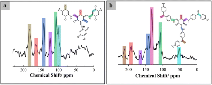 | ||
| Fig. 2 Structural characterization of the COF structure: (a) 13C CP-MAS solid-state NMR spectra of HqTpCOF and (b) 13C CP-MAS solid-state NMR spectra of BpTpCOF. | ||
After Zn was deposited on the anode at a current density of 1 mA cm−2 for 1 h, ex situ GIXAS was employed to specifically characterize the Zn speciation on the electrode surface. Herein, GIXAS was carried out by using the incident X-rays on the electrode surface at a grazing incident angle of 0.3°. Consequently, the corresponding fluorescence signal related to the Zn speciation was detected to measure the XANES and EXAFS spectra at the Zn K-edge. According to XANES and EXAFS data, it is seen that the Zn species deposited on the anode without COF layers (Zn@SS) exhibited Zn(0) characteristics. The addition of COF layers, HqTpCOF@Zn@SS and BpTpCOF@Zn@SS, enabled the absorption edge of XANES spectra at the Zn K-edge to shift to a higher energy, which is relatively close to the absorption edge of Zn2+ species in standard compounds ZnSO4 and (CH3COO)2Zn. This observation indicates the coordination of Zn2+ on the COF structures. It is reported that the hydrated ZnSO4 and (CH3COO)2Zn have a coordination number of 6.32 Thus, via the XANES white-line intensities, the coordination number of COF layers are seen to be less than 6. In Fig. 3, analysis of the local structure regarding the EXAFS data, plotted in the radial distance distribution (R-space), indicates the alteration of the first-shell scattering of Zn species. Herein, the first-shell scattering of BpTpCOF@Zn@SS and HqTpCOF@Zn@SS was observed at around 1.5 Å, which can be assigned to the characteristic Zn2+–O distance in a similar fashion with the standard compounds ZnSO4 and (CH3COO)2Zn. EXAFS data confirm that Zn2+ could be bound with the COF structure before the Zn deposition process occurred on the Zn surface. In Fig. S6 and S7,† the bonding between Zn2+ and the C![[double bond, length as m-dash]](https://www.rsc.org/images/entities/char_e001.gif) O and N–H functional groups in the structure of COFs was confirmed via XPS; the COF powder was soaked in a 2 M ZnSO4 + 0.2 M MnSO4 electrolyte. It is significant that the binding energies adsorbed around 1023 eV and 1045 eV for Zn 2p indicated the Zn2+ binding on the COF structure. In Tables S1 and S2,† to compare COF pristine and COF soaked, the deconvoluted C 1s spectra, both HqTpCOF and BpTpCOF after soaking in the electrolyte indicated the % C
O and N–H functional groups in the structure of COFs was confirmed via XPS; the COF powder was soaked in a 2 M ZnSO4 + 0.2 M MnSO4 electrolyte. It is significant that the binding energies adsorbed around 1023 eV and 1045 eV for Zn 2p indicated the Zn2+ binding on the COF structure. In Tables S1 and S2,† to compare COF pristine and COF soaked, the deconvoluted C 1s spectra, both HqTpCOF and BpTpCOF after soaking in the electrolyte indicated the % C![[double bond, length as m-dash]](https://www.rsc.org/images/entities/char_e001.gif) O decreased. In contrast, the percentage of quaternary nitrogen in the N 1s spectra (C–N+–H3, 401.75 eV) increased, thus the interaction between Zn2+ and the C
O decreased. In contrast, the percentage of quaternary nitrogen in the N 1s spectra (C–N+–H3, 401.75 eV) increased, thus the interaction between Zn2+ and the C![[double bond, length as m-dash]](https://www.rsc.org/images/entities/char_e001.gif) O and N–H functional groups in the COF structure was confirmed.
O and N–H functional groups in the COF structure was confirmed.
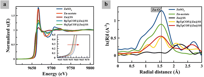 | ||
| Fig. 3 (a) Zn K-edge XANES spectra at the surface of different zinc electrodes and (b) EXAFS spectra in the R-space for different zinc electrodes at 1 mA h cm−2 charged in a symmetrical cell. | ||
3.2. Performance of ZIBs in a symmetrical configuration
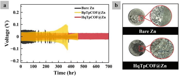
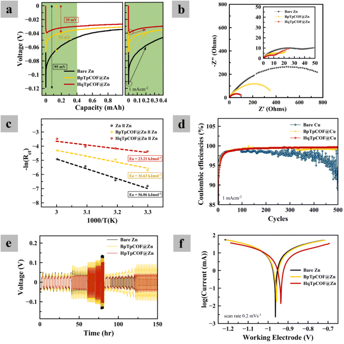
To evaluate the electrochemical performance of the electrodes, GCD tests were carried out. In Fig. 4a, long-term GCD at a current density of 1 mA cm−2 and a capacity of 1 mA h cm−2 was implemented. After 120 h, the bare Zn electrode is seen to a short-circuit due to the growth of dendrites. As for the BpTpCOF@Zn anode, after 370 h, the battery failed because the hydrogen gas present in the battery caused excessive pressure within the battery cell (Fig. S2†). In contrast, the HqTpCOF@Zn anode ran longer than 700 h without any problem. After the battery failed, the coil cell was disassembled and observed. In Fig. 4b, it is clearly seen that the battery failed owing to the accumulation of Zn on the bare Zn electrode. The Zn deposited on HqTpCOF@Zn was more distributed than that on bare Zn. The conjugated ligands to building the COF structure provide from π–π stacking, which can significantly promote the conductivity by inducing the delocalization and distributed electrons resulting in a decrease in the accumulation of Zn on the anode.33In Fig. 5a, the voltage profile of bare Zn and the COF layer coated on the Zn foil (COFs@Zn) for the first plating at a current density of 1 mA cm−2 and a capacity of 1 mA h cm−2 is shown. The overpotentials of bare Zn, BpTpCOF@Zn, and HqTpCOF@Zn were found to be 95, 55, and 39 mV, respectively. Consequently, it is seen that the effect of COFs@Zn (BpTp@Zn and HqTp@Zn) reduced the nucleation overpotential of Zn deposition. In general, nucleation overpotential refers to the difference between the lowest position (sharp potential drop) and the plateau line (equilibrium potential) in the following plating process, which relates to a lower energy barrier for Zn deposition.19 In Fig. 5a, both the tip and plateau potentials clarify Zn nucleation and Zn growth. The sharp profiles induce rapid formation of Zn nuclei in the range of 0–0.4 mA h cm−2 and contribute to the subsequent aggregation into dendrites of 0.01–0.4 mA h cm−2. It is noted that the COFs@Zn electrode exhibits a reduced voltage gap between the tip and plateau potential compared to the bare Zn electrode, which demonstrates more favorable and spontaneous Zn2+ transport through the COF layer.
In Fig. 5b, the Zn nucleation behavior is related to electrochemical impedance spectroscopy (EIS). EIS was performed at the initial cycle and after 50 cycles. The results reveal that charge transfer resistance is improved when compared with bare Zn, accelerating the Zn2+ transfer rate. The COF layer as a solid zinc ion conductor interface can accelerate the Zn ion transfer rate. During the transfer of Zn2+ in the bulk electrolyte, Zn2+ has six molecules of water (Zn(H2O)62+) surrounding it. The de-solvation effect of Zn2+ is significantly promoted by the COF layer. To confirm the ability of the COF interface, the activation energy (Ea) can explain the de-solvation barrier to Zn2+ transport. By performing EIS, fitted with an equivalent circuit (Fig. S10†) with ZSimpWin software, Rct at different temperatures (Table S5†) can calculate Ea, which represents the de-solvation energy barrier, according to the equation:34–36
 | (1) |
![[double bond, length as m-dash]](https://www.rsc.org/images/entities/char_e001.gif) O and N–H functional groups can facilitate Zn2+ transport at the electrode–electrolyte interface and reduce the energy loss in Zn deposit/dissolution processes.
O and N–H functional groups can facilitate Zn2+ transport at the electrode–electrolyte interface and reduce the energy loss in Zn deposit/dissolution processes.
In Fig. 5d, to evaluate the Zn reversibility, CE was determined. The bare Cu electrode was found to be unstable (<98%CE). It is seen that the CE of COFs@Cu provided more stability than bare Cu, especially HqTpCOF@Cu (>99%). In Fig. 5e, the rate performance of the symmetrical cells at various current densities of the COF layer demonstrates the stability of the cycling performance, Zn nucleation decreased.
To investigate anode corrosion, Tafel plots were recorded. In Fig. 5f, the results show that the corrosion potential (Ecorr) of HqTpCOF@Zn slightly shifted towards the positive side. In general, a high Ecorr value represents a good anticorrosion property of the coating and a low icorr value indicates a slow corrosion rate.39,40 In Fig. S11,† the corrosion properties of the COFs@Zn electrodes were determined via the values of the corrosion potential (Ecorr) and corrosion current (icorr). During the process of reduction, it is clearly seen that bubbles of gas occurred on the surface of the electrodes. In the case of the HqTpCOF@Zn electrode, the HqTpCOF layer was protected from the HER. In Fig. S12,† different electrodes were immersed in the electrolyte for 14 days. Similarly, bubbles of gas formed on the surface of the electrodes except for the HqTpCOF@Zn electrode, which confirms that HqTpCOF@Zn not only reduced the HER but also decreased Zn corrosion.
A COF layer is able to protect a Zn metal interface from direct contact with water in the electrolyte. As a result, Zn corrosion and the HER decreased. During the process of reduction on the anode side, the mechanism can be expressed as follows:
| Zn → Zn2+ + 2e− | (2) |
| 2H2O + 2e− ⇌ H2 + OH− | (3) |
| 4Zn2+ + 6OH− + SO42− + xH2O ⇌ ZnSO4(OH)6·xH2O | (4) |
![[double bond, length as m-dash]](https://www.rsc.org/images/entities/char_e001.gif) O and N–H, instead of 6 molecules of H2O is able to reduce the amount of H2O molecules at the surface of the Zn anode upon Zn deposition. Thus, both the HER and OH− are reduced, and the formation of ZHS is also alleviated.
O and N–H, instead of 6 molecules of H2O is able to reduce the amount of H2O molecules at the surface of the Zn anode upon Zn deposition. Thus, both the HER and OH− are reduced, and the formation of ZHS is also alleviated.
In Fig. 6, the XRD results show that after 50 and 100 cycles, the diffraction peaks at 8.068° refer to ZHS. The bare Zn demonstrates a sharp passivation peak higher than HqTpCOF. Such an outcome indicates that HqTpCOF not only reduces the formation of dendrites and the Zn energy barrier but also decreases the side reactions on the surface of the Zn anode.
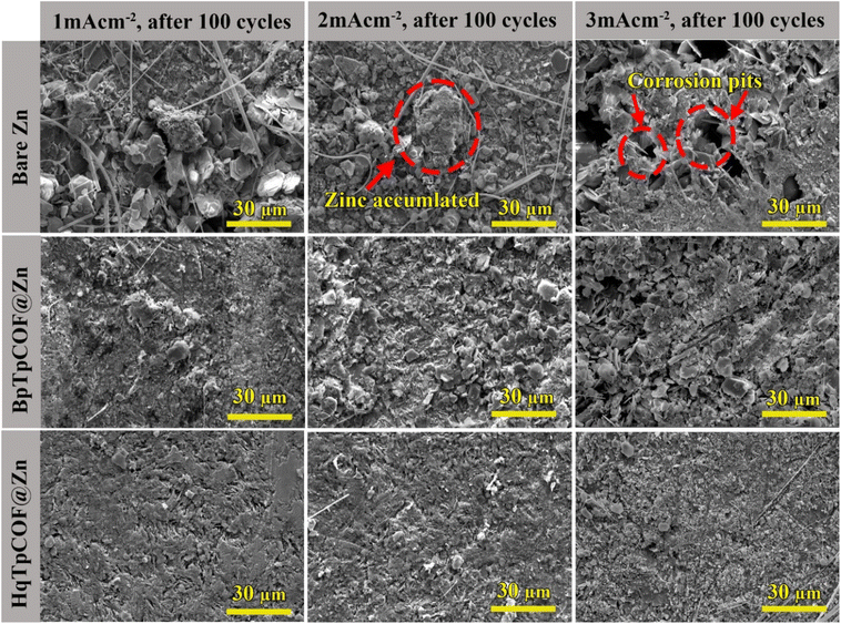
To study the effect of the COF coating layer on the Zn electrodes, the symmetrical cells were tested at various current densities of 1 mA cm−2, 2 mA cm−2 and 3 mA cm−2 for 100 cycles. In Fig. 7, the FE-SEM images of the surface electrodes after being disassembled at various current densities are illustrated. At 3 mA cm−2, bare Zn reveals corrosion pits on the bare Zn electrode caused by Zn corrosion. At 2 mA cm−2, the surface of bare Zn is seen to have an accumulation of Zn. Over long-term cycling, Zn is transformed into Zn dendrites. It is noted that dendrites can be formed if the current goes beyond the ion diffusion limit; current densities can affect the Zn electrodeposition behavior within the metal electrode.41 In contrast, the surfaces of BpTpCOF@Zn and HqTpCOF@Zn remained flat and dense, indicating that COFs can regulate Zn deposition onto their structure at various current densities. The morphologies of the above-mentioned electrodes are related to the voltage profile behavior, as shown in Fig. 5a.
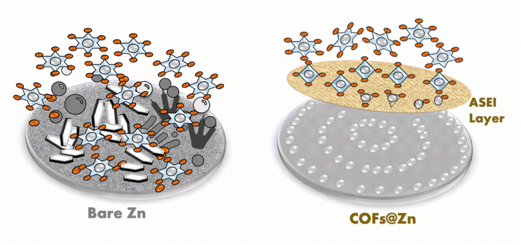
In Fig. 8, the function of COF-ASEIs, as a protective layer for the Zn anode, is illustrated. The COFs improve the plating/stripping kinetics of Zn and provide a uniform Zn2+ diffusion flux by changing the surrounding of Zn2+ at the anode interface, from the water-coordinated Zn2+ to the bonding of Zn2+ with the C![[double bond, length as m-dash]](https://www.rsc.org/images/entities/char_e001.gif) O and N–H functional groups in COFs, resulting in a reduction of desolvation penalty and limiting the activity of water at the anode surface. As a result, side reactions, i.e. HER, Zn-self corrosion, and ZHS, were minimized, providing better stability of the Zn anode upon cycling. In Table S6,† the performance of the Zn anode having an organic framework (ASEIs), as found in the literature, is shown. It is seen that HqTpCOF@Zn showed outstanding stability (>700 h) and exhibited lower overpotential (39 mV) than that of several systems listed in the table. Thus, it is evident that HqTpCOF is one of the most promising ASEI materials for aqueous Zn-based batteries.
O and N–H functional groups in COFs, resulting in a reduction of desolvation penalty and limiting the activity of water at the anode surface. As a result, side reactions, i.e. HER, Zn-self corrosion, and ZHS, were minimized, providing better stability of the Zn anode upon cycling. In Table S6,† the performance of the Zn anode having an organic framework (ASEIs), as found in the literature, is shown. It is seen that HqTpCOF@Zn showed outstanding stability (>700 h) and exhibited lower overpotential (39 mV) than that of several systems listed in the table. Thus, it is evident that HqTpCOF is one of the most promising ASEI materials for aqueous Zn-based batteries.
3.3. Performance of the full cells
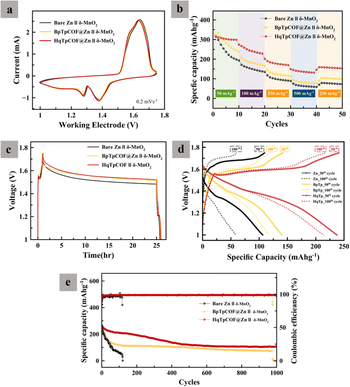
In Fig. 9a, CV curves at different anodes are shown. Both reduction and oxidation have similar redox peaks. The COF layers, HqTp and BpTp films, did not affect the mechanism of redox reactions in the δ-MnO2 cathode. However, when the redox peaks of COFs slightly shifted towards the negative side, Zn reversibility improved in comparison with bare Zn. In Fig. 9b, the capacity of COFs@Zn//δ-MnO2 is seen to be greater than bare Zn//δ-MnO2, proving better redox reaction kinetic behavior in the COFs@Zn system. In Fig. 9c, self-discharge of the batteries was examined. The batteries were charged to 1.75 V and then rested 24 h after that discharged to 1 V. The results revealed the effect of side reactions that occurred in the system. The CEs of HqTp, BpTp, and bare Zn were found to be 97.09, 92.55, and 88.88% respectively, indicating that the COF layers can prevent both Zn corrosion and ZHS that formed on the Zn surface. The CE of the full cells depends on both the cathode and anode. To understand the properties of the anode, a long cycling test is required. In Fig. 9d, it is seen that from the start until the 100th cycle, the specific capacity of the battery faded very fast, especially that of bare Zn//δ-MnO2. After 120 cycles, the bare Zn//δ-MnO2 battery failed because a short-circuit occurred on the Zn anode side due to dendritic corrosion. In Fig. 9e, HqTpCOF@Zn//δ-MnO2 maintained the specific capacity of the battery better than that of bare Zn. It is noted that the ASEI is one of the key parameters to improve the stability of AZIBs and the overall battery performance.4. Conclusion
In this work, two COFs, HqTpCOF and BpTpCOF, which were synthesized via a condensation reaction between the aldehyde linker and amine linkers, were examined. From the XANES and EXAFS results, it was found that the COF-ASEI layer, as a protective layer for the Zn anode, can retard the coordination of water at the electrolyte–Zn interface, signifying an improved Zn plating/stripping kinetics. The use of COFs increases the stability of the Zn anode by regulating the uniform Zn2+ diffusion flux, denoting a uniform Zn deposition at the surface. In addition, side reactions such as HER, Zn corrosion, and ZHS, which occurred due to the contribution of protons, were found to be very minimal compared to that of the use of bare Zn. The Zn anode having HqTpCOF possesses high CE (>99%) and outstanding stability (can cycle at least 700 h at a current density of 1 mA cm−2 and a capacity of 1 mA h cm−2). The full cell (Zn/MnO2) test results showed that the samples having COFs provide much improved cyclability (>1000 cycles at 250 mA g−1) and rate capability, which is in good agreement with that of the half-cell test. Overall, the COFs show promising features as an ASEI material for aqueous Zn-based batteries.Data availability
The authors declare that all data supporting the findings of this study are available within the paper and its ESI.†Author contributions
Conceptualization: V. A. and S. K. Methodology: V. A., W. K., M. G., S. W. and S. K. Experiments: V. A., J. S. and S. W. Formal analysis: V. A., W. K., S. W., A. A. M., P. P., C. S. and S. K. Visualization: V. A. Funding acquisition: S. K. Supervision: S. K. Writing – original draft: V. A. and S. K. Writing – review and editing: all authors.Conflicts of interest
The authors declare no potential competing interests.Acknowledgements
The Program Management Unit for Human Resources & Institutional Development, Research, and Innovation (B16F640166), and the Energy Storage Cluster, Chulalongkorn University are acknowledged. V. A. thanks Chulalongkorn Academic Advancement into its 2nd Century Project. W. L. gratefully acknowledges the National Science of Technology Council (NSTC) project grant no. NSTC 111-2622-E-033-007, 111-2811-E-033-001-MY3, 111-2221-E-033-004-MY3, 111-2923-E-006-009 and 111-3116-F-011-005.References
- G. Fang, J. Zhou, A. Pan and S. Liang, ACS Energy Lett., 2018, 3, 2480–2501, DOI:10.1021/acsenergylett.8b01426.
- A. Konarov, N. Voronina, J. H. Jo, Z. Bakenov, Y.-K. Sun and S.-T. Myung, ACS Energy Lett., 2018, 3, 2620–2640, DOI:10.1021/acsenergylett.8b01552.
- J. Yang, B. Yin, Y. Sun, H. Pan, W. Sun, B. Jia, S. Zhang and T. Ma, Nano-Micro Lett., 2022, 14, 42, DOI:10.1007/s40820-021-00782-5.
- P. Ruan, S. Liang, B. Lu, H. J. Fan and J. Zhou, Angew. Chem., Int. Ed., 2022, 61, e202200598, DOI:10.1002/anie.202200598.
- R. Khezri, S. Rezaei Motlagh, M. Etesami, A. A. Mohamad, F. Mahlendorf, A. Somwangthanaroj and S. Kheawhom, Chem. Eng. J., 2022, 449, 137796, DOI:10.1016/j.cej.2022.137796.
- W. Kao-ian, A. A. Mohamad, W.-R. Liu, R. Pornprasertsuk, S. Siwamogsatham and S. Kheawhom, Batteries Supercaps, 2022, 5, e202100361, DOI:10.1002/batt.202100361.
- Y. Mu, T. Zhou, D. Li, W. Liu, P. Jiang, L. Chen, H. Zhou and G. Ge, Chem. Eng. J., 2022, 430, 132839, DOI:10.1016/j.cej.2021.132839.
- C. Li, L. Wang, J. Zhang, D. Zhang, J. Du, Y. Yao and G. Hong, Energy Storage Mater., 2022, 44, 104–135, DOI:10.1016/j.ensm.2021.10.020.
- W. Kao-ian, M. T. Nguyen, T. Yonezawa, R. Pornprasertsuk, J. Qin, S. Siwamogsatham and S. Kheawhom, Mater. Today Energy, 2021, 21, 100738, DOI:10.1016/j.mtener.2021.100738.
- Y. Zhang, X. Zheng, N. Wang, W.-H. Lai, Y. Liu, S.-L. Chou, H.-K. Liu, S.-X. Dou and Y.-X. Wang, Chem. Sci., 2022, 13, 14246–14263, 10.1039/D2SC04945G.
- Z. Kang, C. Wu, L. Dong, W. Liu, J. Mou, J. Zhang, Z. Chang, B. Jiang, G. Wang, F. Kang and C. Xu, ACS Sustainable Chem. Eng., 2019, 7, 3364–3371, DOI:10.1021/acssuschemeng.8b05568.
- D. Yuan, W. Manalastas, Jr., L. Zhang, J. J. Chan, S. Meng, Y. Chen and M. Srinivasan, ChemSusChem, 2019, 12, 4889–4900, DOI:10.1002/cssc.201901409.
- J. Cao, D. Zhang, X. Zhang, M. Sawangphruk, J. Qin and R. Liu, J. Mater. Chem. A, 2020, 8, 9331–9344, 10.1039/D0TA02486D.
- H. Jia, Z. Wang, B. Tawiah, Y. Wang, C.-Y. Chan, B. Fei and F. Pan, Nano Energy, 2020, 70, 104523, DOI:10.1016/j.nanoen.2020.104523.
- J. Zhao, Y. Ying, G. Wang, K. Hu, Y. D. Yuan, H. Ye, Z. Liu, J. Y. Lee and D. Zhao, Energy Storage Mater., 2022, 48, 82–89, DOI:10.1016/j.ensm.2022.02.054.
- Z. Song, J. Ding, B. Liu, Y. Shen, J. Liu, X. Han, Y. Deng, C. Zhong and W. Hu, Chem. Eng. J., 2022, 429, 132331, DOI:10.1016/j.cej.2021.132331.
- M. Gopalakrishnan, S. Ganesan, M. T. Nguyen, T. Yonezawa, S. Praserthdam, R. Pornprasertsuk and S. Kheawhom, Chem. Eng. J., 2023, 457, 141334, DOI:10.1016/j.cej.2023.141334.
- L. Cao, D. Li, T. Deng, Q. Li and C. Wang, Angew. Chem., Int. Ed., 2020, 59, 19292–19296, DOI:10.1002/anie.202008634.
- J. H. Park, M.-J. Kwak, C. Hwang, K.-N. Kang, N. Liu, J.-H. Jang and B. A. Grzybowski, Adv. Mater., 2021, 33, 2101726, DOI:10.1002/adma.202101726.
- S.-m. Zeng, X.-x. Huang, Y.-j. Ma and L.-j. Zhi, New Carbon Mater., 2021, 36, 1–18, DOI:10.1016/S1872-5805(21)60001-X.
- A. P. Côté, A. I. Benin, N. W. Ockwig, M. O'Keeffe, A. J. Matzger and O. M. Yaghi, Science, 2005, 310, 1166–1170, DOI:10.1126/science.1120411.
- S. Gu, S. Wu, L. Cao, M. Li, N. Qin, J. Zhu, Z. Wang, Y. Li, Z. Li, J. Chen and Z. Lu, J. Am. Chem. Soc., 2019, 141, 9623–9628, DOI:10.1021/jacs.9b03467.
- S. Wang, Q. Wang, P. Shao, Y. Han, X. Gao, L. Ma, S. Yuan, X. Ma, J. Zhou, X. Feng and B. Wang, J. Am. Chem. Soc., 2017, 139, 4258–4261, DOI:10.1021/jacs.7b02648.
- K. Jeong, S. Park, G. Y. Jung, S. H. Kim, Y.-H. Lee, S. K. Kwak and S.-Y. Lee, J. Am. Chem. Soc., 2019, 141, 5880–5885, DOI:10.1021/jacs.9b00543.
- A. Khayum, M. M. Ghosh, V. Vijayakumar, A. Halder, M. Nurhuda, S. Kumar, M. Addicoat, S. Kurungot and R. Banerjee, Chem. Sci., 2019, 10, 8889–8894, 10.1039/C9SC03052B.
- Y. Min, L. Guo, G. Wei, D. Xian, B. Zhang and L. Wang, Chem. Eng. J., 2022, 443, 136480, DOI:10.1016/j.cej.2022.136480.
- L. Sheng, L. Wang, J. Wang, H. Xu and X. He, Chem. Commun., 2020, 56, 10465–10468, 10.1039/D0CC04324A.
- A. Abbasi, Y. Xu, E. Abouzari-Lotf, M. Etesami, R. Khezri, S. Risse, N. Kardjilov, K. Van Tran, H. Jia, A. Somwangthanaroj, I. Manke, Y. Lu and S. Kheawhom, Electrochim. Acta, 2022, 435, 141365, DOI:10.1016/j.electacta.2022.141365.
- S. Kandambeth, A. Mallick, B. Lukose, M. V. Mane, T. Heine and R. Banerjee, J. Am. Chem. Soc., 2012, 134, 19524–19527, DOI:10.1021/ja308278w.
- X. Wang and Y. Li, Chem. – Eur. J., 2003, 9, 300–306, DOI:10.1002/chem.200390024.
- Y. Liu, J. Wei, Y. Tian and S. Yan, J. Mater. Chem. A, 2015, 3, 19000–19010, 10.1039/C5TA05507E.
- H. Liu, G.-M. Chen, J. Ma, Y.-X. Fan and Z.-Y. Tao, Optik, 2022, 253, 168594, DOI:10.1016/j.ijleo.2022.168594.
- C. Li, L. Liu, J. Kang, Y. Xiao, Y. Feng, F.-F. Cao and H. Zhang, Energy Storage Mater., 2020, 31, 115–134, DOI:10.1016/j.ensm.2020.06.005.
- T. Okumura, T. Fukutsuka, K. Matsumoto, Y. Orikasa, H. Arai, Z. Ogumi and Y. Uchimoto, J. Phys. Chem. C, 2011, 115, 12990–12994, DOI:10.1021/jp202967d.
- Z. Zhao, R. Wang, C. Peng, W. Chen, T. Wu, B. Hu, W. Weng, Y. Yao, J. Zeng, Z. Chen, P. Liu, Y. Liu, G. Li, J. Guo, H. Lu and Z. Guo, Nat. Commun., 2021, 12, 6606, DOI:10.1038/s41467-021-26947-9.
- Y. Zhou, G. Li, S. Feng, H. Qin, Q. Wang, F. Shen, P. Liu, Y. Huang and H. He, Adv. Sci., 2023, 10, 2205874, DOI:10.1002/advs.202205874.
- D. Kundu, S. Hosseini Vajargah, L. Wan, B. Adams, D. Prendergast and L. F. Nazar, Energy Environ. Sci., 2018, 11, 881–892, 10.1039/C8EE00378E.
- J. Cao, D. Zhang, R. Chanajaree, Y. Yue, Z. Zeng, X. Zhang and J. Qin, Adv. Powder Mater., 2022, 1, 100007, DOI:10.1016/j.apmate.2021.09.007.
- B. N. Grgur, A. R. Elkais, M. M. Gvozdenović, S. Ž. Drmanić, T. L. Trišović and B. Z. Jugović, Prog. Org. Coat., 2015, 79, 17–24, DOI:10.1016/j.porgcoat.2014.10.013.
- C. Chen, S. Qiu, S. Qin, G. Yan, H. Zhao and L. Wang, Int. J. Electrochem. Sci., 2017, 12, 3417–3431, DOI:10.20964/2017.04.47.
- P. Xiong, Y. Zhang, J. Zhang, S. H. Baek, L. Zeng, Y. Yao and H. S. Park, EnergyChem, 2022, 4, 100076, DOI:10.1016/j.enchem.2022.100076.
Footnote |
| † Electronic supplementary information (ESI) available. See DOI: https://doi.org/10.1039/d3nr00898c |
| This journal is © The Royal Society of Chemistry 2023 |

