A low resistance and stable lithium-garnet electrolyte interface enabled by a multifunctional anode additive for solid-state lithium batteries†
Chencheng
Cao
a,
Yijun
Zhong
 a,
Kimal
Chandula Wasalathilake
a,
Moses O.
Tadé
a,
Xiaomin
Xu
a,
Kimal
Chandula Wasalathilake
a,
Moses O.
Tadé
a,
Xiaomin
Xu
 a,
Hesamoddin
Rabiee
cd,
Md
Roknuzzaman
 e,
Rajib
Rahman
e and
Zongping
Shao
 *ab
*ab
aWA School of Mines: Minerals, Energy and Chemical Engineering (WASM-MECE), Curtin University, Perth, WA 6102, Australia. E-mail: zongping.shao@curtin.edu.au
bState Key Laboratory of Materials-Oriented Chemical Engineering, College of Chemical Engineering, Nanjing Tech University, Nanjing, 211816, China
cCentre for Future Materials, University of Southern Queensland, Springfield Central, QLD 4300, Australia
dAustralia Centre for Water and Environmental Biotechnology (ACWEB), The University of Queensland, St. Lucia, Queensland 4072, Australia
eSchool of Physics, University of New South Wales, Sydney, NSW 2052, Australia
First published on 24th November 2021
Abstract
Solid-state batteries (SSBs) have attracted considerable attention due to their high intrinsic stability and theoretical energy density. As the core part, garnet electrolyte has been extensively investigated due to its high lithium-ion conductivity, wide electrochemical potential window, and easy synthesis. However, the poor and electrochemically unstable interfacial contact between the electrolyte and lithium anode greatly impedes the practical use of garnet based SSBs. Here, we report that such an interface challenge can be perfectly tackled by introducing multifunctional Li0.3La0.5TiO3 (LLTO) as an additive into the lithium anode. The limited reaction between the LLTO and lithium effectively changes the physical properties of the lithium anode, making it perfectly compatible with the garnet surface, and consequently significantly decreasing the interfacial resistance from 200 to only 48 Ω cm2 and greatly improving the interface stability and avoiding dendrite formation. Interestingly, LLTO provides additional lithium storage, and the close interface contact and the high lithium-ion conductivity of LLTO ensure high rate performance. Consequently, the symmetrical cell runs stably at 0.1 mA cm−2 for 400 h without obvious degradation. The SSB assembled with the LiFePO4 cathode and Li-LLTO composite anode demonstrates a specific capacity of 147 mA h g−1 and remarkable cycling stability with only 10% capacity decay over 700 cycles at 1C.
Introduction
Lithium-ion batteries (LIBs) are an important type of electrochemical energy storage device, and have been widely used in personal portable devices and will play an important role in future sustainable energy systems.1,2 However, conventional LIBs that use combustible organic-based electrolytes and intercalation-type graphite anodes suffer from safety issues and limited energy density.3–5 With the quickly rising demand for large-scale electrochemical energy storage and the rapid growth in electric vehicles, new battery systems with higher capacity and safety are urgently needed. In the past, many research studies have been concentrated on the advancement of alternative LIBs with improved energy density and safety.6–9 Among them, solid-state lithium batteries (SSBs) have drawn particular attention because of the non-flammable nature of the solid electrolyte and high theoretical specific capacity (3860 mA h g−1) of metallic lithium (compared to only 375 mA h g−1 for a typical graphite anode).10–13 It is believed that SSBs are the perfect solution for the safety issue of LIBs for use in electric vehicles. Unfortunately, the low conductivity of the solid electrolyte and poor and unstable contact between the lithium anode and solid electrolyte have become the main barriers to the practical use of SSBs.Currently, solid-state electrolytes (SSEs) for SSBs can be divided into two classes: inorganic14–18 and polymer electrolytes.19–22 Among them, inorganic electrolytes are of particular interest due to their higher intrinsic stability. Among the various inorganic electrolytes, garnet-type SSEs23–28 have been broadly studied because of the outstanding chemical compatibility with Li metal, high electrochemical stability, the lowest reduction potential against Li, and high Li-ion conductivity at room temperature.29,30 Based on the theoretical calculations and experimental studies, garnet-type Li7La3Zr2O12 (LLZO) is deemed to be the most promising garnet-type electrolyte material which can reach ionic conductivities over 10−3 S cm−1 at room temperature by element doping of the Zr site with Ta or Nb at an appropriate amount.28,31,32 Although garnet SSEs show distinct merits, their ultimate application in SSBs for commercialisation is still restrained due to the high interface resistance caused by the poor and unstable surface contact between the garnet electrolyte and Li metal, which is related to the lithiophobic nature of the garnet electrolyte surface.33–36 Thus, it is unrealistic to coat Li directly on garnet SSEs because of the poor wettability between SSEs and Li metal. To make matters worse, the interface issue could further deteriorate during the Li plating/stripping process as contact loss and interface voids may appear between Li metal and SSEs. As a result, insufficient point-to-point physical connection between the uneven Li metal anode and the garnet electrolytes could be further triggered by poor surface contact, leading to a heterogeneous Li-ion flux distribution during the charging and discharging process, and consequently dendrite formation.37
To resolve the above interface issues, many attempts have been made to alter the properties of the electrolyte surface from lithiophobic to lithiophilic through surface modification. It is believed that the surface Li2CO3 is the cause of the lithiophobic nature of the garnet. Therefore, to increase the surface contact, some researchers have tried to remove surface debris by adding inorganic additives (such as LiF and Li3PO4)38,39 to impede Li2CO3 formation or carbon to get rid of Li2CO3 through its reaction with the garnet surface Li2CO3 at high temperature.40 Applying high external pressure is an alternative strategy to eliminate the interface resistance by enhancing the physical contact, which can also potentially remove the Li2CO3 passivation layer and control the grain boundary sizes and the garnet microstructure.41 However, these methods/strategies may cause lithium loss and the formation of electrochemically conductive defects. In addition, it is unavoidable to regenerate the surface once it is contaminated accidentally. Other than removing surface contaminants, another method is to improve the wettability of molten Li through adjusting its properties by introducing additives or other components. Various oxide materials have been utilised as additives that can form Li alloys, for instance, Li–Mg,42 Li–Al,43 Li–Mo,44 Li–Sn,45 and Li–Si,46 which effectively improve the surface contact between lithium metal and garnet electrolyte. Apart from that, nitride materials, such as g-C3N4 (ref. 47) and Si3N4,48 have also been used to improve the surface contact on the anode side. In our previous studies, we have found that, by introducing Si3N4 (ref. 48) and α-MoO3 (ref. 44) as anode additives, the resulting composites with reduced surface tension of the lithium anode effectively improved the contact between the electrolyte and the anode. It is noted that, during the melting and coating process, vigorous reactions of these additive components with lithium often occurred, which might lead to unfavourable products (Li2O for example) that have negative effects on the ion and electron transfer at the interface on the one hand and consume partial lithium without contributing to capacity on the other hand. To reduce such negative effects on the overall battery capacity, the additives should be in a minimum amount. However, if a structurally stable additive that not only improves the anode–electrolyte contact but also provides extraordinary benefits for ensuring ion and electron transfer at the interface during the electrochemical Li stripping/plating and contributing additional capacity is used, the above negative effects will be eliminated, and it is thus highly sought after.
Pristine perovskite-type Li0.3La0.5TiO3 (LLTO) was previously reported as a superionic conductor for Li+.49–51 However, partial electrochemical reduction of the Ti element occurs if LLTO is indirect contact with Li, leading to a substantial increase of electronic conductivity.52 Thus, use of LLTO as a solid electrolyte is greatly inhibited. In this work, by taking advantage of the limited reaction of LLTO with Li metal and the high Li+ conductivity of LLTO, we introduce LLTO as an additive to the lithium anode to tackle the poor contact problem of the garnet electrolyte with the lithium anode. Both DFT calculations and experiments confirm that the incorporation of LLTO into the lithium anode significantly improved the wettability of the anode to the garnet surface, thus ensuring superior durability and low interface resistance. The improved surface contact and the lithium-ion conducting and lithium-ion storage capability of the LLTO phase bring about high capacity, rate performance and stability of the cell. Full SSBs with a Li-LLTO composite anode and LiFePO4 cathode demonstrate excellent electrochemical performance from the aspects of capacity and rate performance, as well as excellent cycling stability.
Results
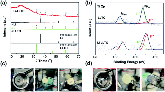
Previously, when using MoO3 as an additive, a violent reaction between MoO3 and Li was observed, so care should be taken to avoid a fire.44 As to the preparation of the Li-LLTO composite, even when a large amount of LLTO was applied, no violent reaction was observed, suggesting the limited reaction between them. To confirm that only a gentle reaction occurred between LLTO and lithium, ex situ XRD characterization was performed. As shown in Fig. 1a, for the metallic Li, one main diffraction peak at 2-theta of 37° was observed, which is in good agreement with the standard pattern of lithium (PDF 00-001-1131). The diffraction patterns of the as-synthesized LLTO powder are well fitted to the standard LLTO phase (PDF 01-070-5198). After thoroughly mixing the lithium and LLTO powder at a weight ratio of 50![[thin space (1/6-em)]](https://www.rsc.org/images/entities/char_2009.gif) :
:![[thin space (1/6-em)]](https://www.rsc.org/images/entities/char_2009.gif) 50 at 250 °C and cooling down to room temperature, the as-obtained mixture (composite) showed an X-ray diffraction (XRD) pattern with the characteristics of both metallic Li and crystalline LLTO, and no additional new phase was observed. The much-reduced peak intensity of lithium suggests that after melting and solidification, the lithium became more amorphous. In addition, as compared to the pristine LLTO, a slight shift of the diffraction peaks of the LLTO phase in the composite to lower angles was also observed, implying lattice expansion. It is likely that the lithium reacted with partial Ti in LLTO, leading to the partial reduction of Ti4+ to Ti3+. To confirm this assumption, X-ray photoelectron spectroscopy (XPS) characterization was conducted on the composite. As shown in Fig. 1b, in the pristine LLTO, most of the Ti is in the +4 oxidation state (85%), while the content of Ti3+ reached 73% in the Li-LLTO composite (Li to LLTO weight ratio of 50
50 at 250 °C and cooling down to room temperature, the as-obtained mixture (composite) showed an X-ray diffraction (XRD) pattern with the characteristics of both metallic Li and crystalline LLTO, and no additional new phase was observed. The much-reduced peak intensity of lithium suggests that after melting and solidification, the lithium became more amorphous. In addition, as compared to the pristine LLTO, a slight shift of the diffraction peaks of the LLTO phase in the composite to lower angles was also observed, implying lattice expansion. It is likely that the lithium reacted with partial Ti in LLTO, leading to the partial reduction of Ti4+ to Ti3+. To confirm this assumption, X-ray photoelectron spectroscopy (XPS) characterization was conducted on the composite. As shown in Fig. 1b, in the pristine LLTO, most of the Ti is in the +4 oxidation state (85%), while the content of Ti3+ reached 73% in the Li-LLTO composite (Li to LLTO weight ratio of 50![[thin space (1/6-em)]](https://www.rsc.org/images/entities/char_2009.gif) :
:![[thin space (1/6-em)]](https://www.rsc.org/images/entities/char_2009.gif) 50). Clearly, the reducing metallic lithium reacted with Ti4+, leading to the partial reduction of Ti4+ to Ti3+. The increase in Ti3+ concentration will introduce partial electronic conductivity to the LLTO, which is unwanted for it as an electrolyte, but beneficial as an anode additive. The limited reaction between LLTO and lithium will minimize the chemical consumption of lithium which will not contribute to the capacity, and thus the negative effect of the additive to the capacity is reduced. In addition, LLTO was reported to have the capability for lithium storage,51 and the store of the LLTO phase in the anode will provide additional capacity for lithium.
50). Clearly, the reducing metallic lithium reacted with Ti4+, leading to the partial reduction of Ti4+ to Ti3+. The increase in Ti3+ concentration will introduce partial electronic conductivity to the LLTO, which is unwanted for it as an electrolyte, but beneficial as an anode additive. The limited reaction between LLTO and lithium will minimize the chemical consumption of lithium which will not contribute to the capacity, and thus the negative effect of the additive to the capacity is reduced. In addition, LLTO was reported to have the capability for lithium storage,51 and the store of the LLTO phase in the anode will provide additional capacity for lithium.
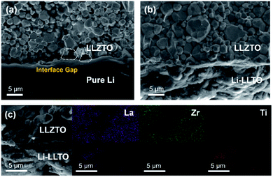
After introducing LLTO into lithium to form a composite, it was found that the surface tension of lithium was greatly reduced, even at a low content of 5 wt%. Our initial test confirms that the pristine molten Li was difficult to coat on the garnet surface due to its lithiophobic nature. It is believed that the surface Li2CO3 impurity may account for this lithiophobic nature. The pure molten lithium showed very high surface tension; as shown in Fig. 1c, once the molten lithium cooled down to room temperature in a stainless-steel (SS) crucible, the lithium solidified into a spherical shape. The SEM image and XRD pattern of the LLZTO pellet are shown in Fig. S1 and S2,† respectively. Also, the surface of garnet was hardly wetted by the lithium as demonstrated in Fig. S3.† Because of the poor wetting behaviour of the pure Li to the garnet electrolyte surface, just a fraction of Li was coated on the garnet surface. As shown in Fig. 2a, an interface void separated the Li and garnet LLZTO. In contrast, even adding just 5 wt% LLTO into molten Li caused the wettability between the garnet surface and molten lithium to be significantly improved, and Li coating on the LLZTO pellet was realized in a short period of time. Above 5 wt% LLTO, the molten Li-LLTO mixture started to become quite flat instead of the spherical shape for the pure molten Li. The surface tension of the lithium was greatly reduced upon introducing LLTO. Once the mixture returned to room temperature, the Li-LLTO composite was still in the form of a drop spread on the top of the crucible and garnet pellet, shown in Fig. 1d and S4,† and within the same surface contact time, the Li-LLTO (5 wt%) composite realized uniform coating on the garnet surface. The SEM images (Fig. 2b) further verified that the Li-LLTO composite can be uniformly coated on the LLZTO pellet. The Li-LLTO composite is firmly attached to the garnet SSE surface without the appearance of any gap at their interface, which further demonstrated the advantage of using LLTO as an anode additive to enhance the compatibility of Li metal with garnet electrolyte. The difference in behaviour of the Li anode melts with/without the LLTO demonstrated the effectiveness of the additive LLTO in modifying the surface contact between the Li metal and the garnet electrolyte. Elemental mapping images of the Li-LLTO and LLZTO garnet interface are shown in Fig. 2c, where the signal of Ti element was distributed on the anode side, as expected.
To understand the origin of the improved compatibility between the Li-LLTO composite and garnet (LLZTO) electrolyte, first-principles density functional theory (DFT) calculations were performed. Firstly, the interaction between Li metal and LLTO perovskite in the composite anode was proven by the binding energy. The binding energy of Li metal on Li0.3La0.5TiO3 (LLTO) was calculated with a variety of Li stoichiometries in LixLa0.5TiO3 (x = 0.5 to 1.2). The results prove a strong interaction between Li metal and LLTO with high binding energies ranging from −10.86 to −25.73 eV. To compare the wettability of Li on LLZTO and Li-LLTO on LLZTO, the interface formation energies of Li| LLZTO and Li-LLTO|LLZTO systems were also evaluated according to46Ef = (Eab − Ea − Eb)/S, where Eab denotes the total energy of the interface, Ea and Eb denote the separated slabs, and S represents the interfacial area. As shown in Fig. 3, the interfacial formation energies of Li|LLZTO and Li-LLTO|LLZTO are −3.31 and −11.31 J m−2, respectively. The Li atoms close to the interface exhibited local disorder while Li atoms far from the interface maintained a relatively ordered structure. The more negative interface formation energy of Li-LLTO|LLZTO than Li|LLZTO indicates the improved wettability of the Li-LLTO composite on the garnet electrolyte.
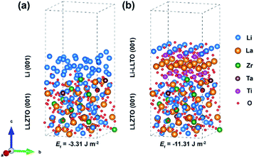 | ||
| Fig. 3 Comparison of interfacial formation energies of anode–electrolyte interfaces validated through DFT calculation: (a) Li|LLZTO and (b) Li-LLTO|LLZTO. | ||
To confirm the beneficial effect of LLTO in the lithium anode for improving the electrochemical performance of SSBs, two types of symmetrical cell were fabricated, which were Li|LLZTO|Li and Li-LLTO|LLZTO|Li-LLTO and their interface resistances were comparatively studied by electrochemical impedance spectroscopy (EIS), from which the electrolyte resistance and the interface resistance can be calculated. As shown in Fig. 4a, the total resistance of the Li|LLZTO|Li cell was around 620 Ω cm,2 while the resistance of the Li-LLTO|LLZTO|Li-LLTO cell was approximately 320 Ω cm2 with 5% LLTO addition in the composite electrode. The semicircle located at the high frequency range can be ascribed to the bulk resistance of the LLZTO electrolyte, while the other semicircle at the low frequency range refers to the interfacial resistance. It can be observed that 5 wt% LLTO addition into the electrode provided the lowest interface resistance and utilised the minimum amount of oxide material which could be beneficial to maintain a superior overall energy density of the anode in practical cells. Therefore, a 5% LLTO ratio was selected for further investigation. The interface polarization resistances are 200 and 48 Ω cm2 for the Li|LLZTO|Li and Li-LLTO|LLZTO|Li-LLTO cells, respectively. It suggests that introducing a small portion of LLTO additive into the electrode effectively improved the Li metal interfacial contact and sped up the Li+ diffusion.51 Electrochemical stripping/plating cycling was conducted to investigate the interfacial stability between the Li-LLTO composite and garnet electrolyte. The critical current density (CCD) is identified as the critical current point where short circuit occurs, which is a crucial factor to describe and examine the Li-garnet interface and an indicator to analyse dendrite growth control. For the CCD test, the current density was raised from 0.05 to 0.8 mA cm−2 with a steady increase. In Fig. 4b, the CCD for the Li|LLZTO|Li cell was only 0.1 mA cm −2 because of the poor interface, while it remained steady and smooth before short circuit happened at 0.4 mA cm−2 for the Li-LLTO|LLZTO|Li-LLTO cell, as demonstrated in Fig. 4c. The improved CCD result can be ascribed to the Li-LLTO composite network which provided a very stable interface between the anode and electrolyte. In addition, the Li-LLTO composite generated a smooth pathway to accelerate Li+ diffusion, while the LLTO particles facilitated the formation of a uniform electric field to prohibit Li dendrite deposition on the anode side. The above-mentioned experimental results imply that the LLTO composite can both improve the interface contact for Li-garnet to minimise the interface resistance, and significantly boost the CCD for the Li-LLTO|LLZTO|Li-LLTO symmetric cells.
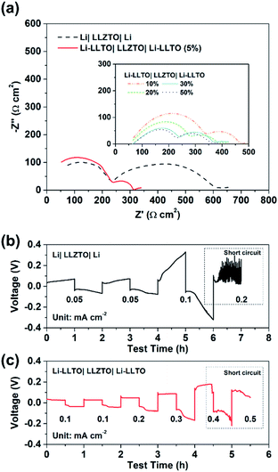 | ||
| Fig. 4 (a) EIS curves for Li symmetric cells with different Li-LLTO compositions. (b) CCD for the pure Li in the Li symmetric cell. (c) CCD for the Li-LLTO composite in the Li symmetric cell. | ||
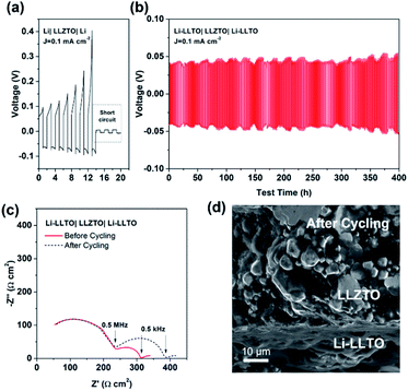
Comparison of the long-term stripping/plating cycling performance for the Li|LLZTO|Li and Li-LLTO|LLZTO|Li-LLTO symmetric cells was also carried out at 0.1 mA cm−2. For the Li|garnet SSE|Li cell, the voltage consistently increased with the cycle numbers (Fig. 5a), implying an unstable solid electrolyte–electrode interface upon cycling. Short circuit happened within the first 15 h of cycling. In comparison, the Li-LLTO|LLZTO|Li-LLTO cell maintained a stable interface resistance during a prolonged Li plating and stripping cycling period of over 400 h (Fig. 5b), and the overall voltage was maintained at around 30–40 mV without an obvious increase. Compared to the Nyquist plot from the EIS before cell cycling, the resistance of the symmetric cells (Fig. 5c) does not show a significant change after a 400 h cycling test. After the cycling, the Li-LLTO|LLZTO|Li-LLTO symmetric cell was disassembled and examined by SEM with the cross-sectional image shown in Fig. 5d. No significant morphological changes were observed at the interface after the long-term cycling test, which should be attributed to the additive LLTO in the Li-LLTO composite anode that made the electrode and electrolyte have better mechanical compatibility.
Based on the above analysis, the two major benefits from the introduction of the LLTO additive into the lithium anode are, as demonstrated in Fig. 6, better contact between the electrolyte and anode and better electron and ion transfer during the electrochemical stripping/plating process. Firstly, better wettability of the molten Li with the LLTO (Fig. 6, left column) led to better anode-electrolyte contact. In contrast, due to the rich surface voids because of the poor wettability of the garnet electrolyte surface by lithium, Li+ and electrons are unable to diffuse efficiently between the anode and the electrolyte for the pure Li cell. This was supported by the digital photos of the garnet electrolyte surface after the anode coating, the low interface resistance value, and the more negative interface formation energy as further revealed by the first-principles DFT calculations. Secondly, the additive LLTO further served as an effective dual ionic-electronic conductor on the anode–electrolyte interface, as demonstrated in Fig. 6 (middle and right columns). It is crucial that the electrochemical reduction of the Ti element took place when LLTO was in direct contact with Li, which could lead to a great enhancement of electronic conductivity for the LLTO. In this work, with a robust LLZTO garnet electrolyte, the LLTO was intentionally integrated into the anode, where such characteristics of the LLTO can be fully utilised for both ionic and electronic conduction. For ion transfer, the LLTO serves as a morphological extension of the electrolyte. For electron transfer, although the electronic conductivity of reduced LLTO may be inferior to that of the metallic Li, the key role of LLTO is to serve as a robust “bridge” between the Li-containing anode and electrolyte. This is very important, especially when the extent of Li stripping is deep. The comparison of the overpotential of Li stripping during the first charging of the symmetric cell clearly supports this assumption. The overpotential remained stable at 30–40 mV during the first charging of the symmetric cell with the Li-LLTO electrode, while the Li|LLZTO|Li symmetric cell demonstrated a high overpotential of ∼30 mV (from 40 to 70 mV). As shown in the Fig. 6 middle column, at the beginning of the Li stripping, the dominant contribution of the overpotential is from the contact between the anode and electrolyte. In this circumstance, the dual conductive feature of the LLTO is supplementary. As the Li stripping went deeper, the Li at the interface was gradually consumed which might have caused more voids and inadequate contact between the electrolyte and Li metal, which brought additional contribution of overpotential (Fig. 6 right column). This resulted in a significant build-up of overpotential for the cell with pure Li. The LLTO “bridge” provided a decent dual electron and ion transport pathway and therefore created no short circuiting or overpotential enlargement. It is also important to note that such a dual conductive characteristic of the LLTO could also benefit the cycling stability of the electrolyte–anode interface. Insufficient interface stability of the Li|LLZTO|Li symmetric cell could be ascribed to the inhomogeneous current distribution and defect Li+ flux. The weak and unstable contact (Fig. 6) between garnet and Li metal is the main reason behind the large cell polarization and short circuit. Owing to the benefits of the LLTO, highly improved and more stable Li+ and electron transfer could be obtained through the interface between the LLZTO electrolyte and Li metal (Fig. 6).
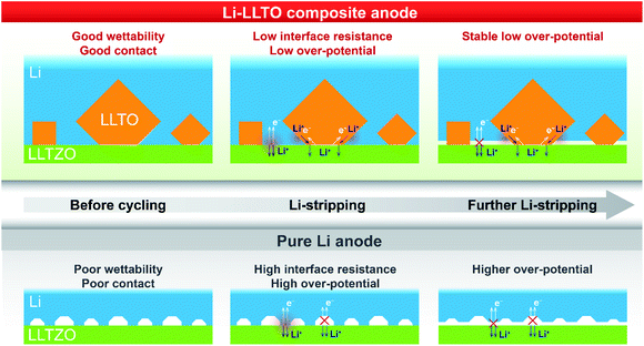 | ||
| Fig. 6 Illustration of electron and ion transfer on the Li|LLZTO interface, the Li|LLZTO interface and the Li-LLTO|LLZTO interface. | ||
To further support the superiority of the Li-LLTO anode, full SSBs were assembled and tested by applying the stable LiFePO4 (LFP) as the cathode with the assembled set-up shown in Fig. 7a. Super P was added due to its electronic conductivity. It was mixed with the cathode and PVDF to form a cathode composite, and a drop of LiPF6 solution was used in between the garnet electrolyte and the cathode to enhance Li+ accessibility to the LFP cathode material to minimize the effect of cathode–electrolyte interface stability on the overall cell performance. Pleasingly, the solid-state LiFePO4|LLZTO|Li-LLTO full cell exhibited a good performance at different charge–discharge rates from 0.1 to 2C. According to Fig. 7b, the specific capacity at rates of 0.1, 0.2, 0.5, 1, and 2C reached 163, 160, 158, 147 and 135 mA h g−1, respectively. Once the discharge rate returned to 0.1C, the specific capacity rapidly recovered to 147 mA h g−1. The cyclic voltammetry (CV) curve is shown in Fig. S5.† The high capacity and excellent rate performance further evidence the benefit of dual ionic and electronic conductivities from the LLTO and the exceptional interfacial contact between the anode and electrolyte.
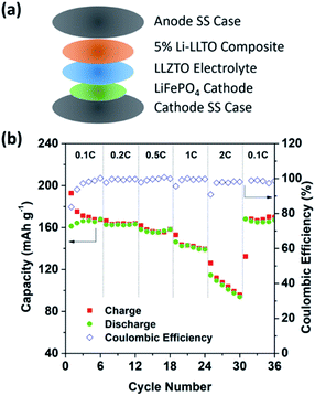 | ||
| Fig. 7 The overall SSB cycling performance. (a) Assembly of the solid-state lithium batteries. (b) Performance of the LiFePO4|LLZTO|Li-LLTO solid-state cells at different charge–discharge rates. | ||
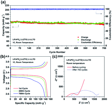
Furthermore, the full SSB demonstrated a capacity retention of 90% (147 mA h g−1) at 1C over 700 cycles, while the coulombic efficiency remained at 99% during the whole charging–discharging process (Fig. 8a and b), indicating an excellent cycling stability. Fig. 8c demonstrated the EIS profile of the fresh and cycled cells. The total resistance of the LiFePO4|LLZTO|Li-LLTO fresh cell was about 700 Ω cm2 while it increased to 1700 Ω cm2 after the long-term cycling. Such increased resistance was mainly contributed by the charge transfer and diffusion process, as indicated by the semicircle in the low frequency range, while the anode–electrolyte interface was less varied according to the semicircle at the high frequency range. In contrast, the short circuit happened for the LiFePO4|LLZTO|Li full cell after 50 cycles, which suggests the unstable electrode–electrolyte interface (Fig. S6†). After the test, the LiFePO4|LLZTO|Li-LLTO cell was disassembled, and the cross-sectional morphology of the cell was observed through SEM. In Fig. S7 and S8,† no significant lithium dendrite formation on the anode side was observed and the morphology of the garnet pellet did not show any prominent change compared with the pristine garnet pellet.
Conclusions
In conclusion, a Li-LLTO composite anode for solid-state batteries (SSBs) was developed. As evidenced by experimental results and supported by DFT calculations, the addition of LLTO in the Li-LLTO composite anode caused sufficient modification of the physicochemical properties of the Li metal anode, thus bringing about a great improvement in wettability on the conventional LLZTO garnet electrolyte and thereby better interface contact. More importantly, the LLTO also served as a robust “bridge” between the Li-containing electrolyte and anode for ensuring efficient electron and ion transfer, especially when a deep Li stripping process occurred. Also, the LLTO enhanced the electrochemical stability of the garnet–anode interface. In consequence, symmetric cells with the Li-LLTO composite anode delivered a lower interface resistance and improved CCD. The full SSB with the LFP cathode and Li-LLTO composite anode demonstrated extraordinary cycling performance in terms of cycling stability with only 10% capacity degradation over 700 cycles. This study will provide inspiration for developing new composite anodes and complicated anode structures that contain mixed ionic and electronic components for tackling interface issues in SSBs.Experimental
Materials synthesis
Li6.4La3Zr1.4Ta0.6O12 (LLZTO) was synthesized via a conventional solid-state reaction. LiOH·H2O (Sigma), La2O3 (Sigma), ZrO2 (Sigma) and Ta2O5 (Sigma) were mixed thoroughly with iso-propanol (IPA) according to the stoichiometric ratio in a high-energy ball mill (Fritsch-Pulverisette 6) for 2 h. 10% extra LiOH·H2O was added to make amends for the Li loss in the high temperature sintering stage. La2O3 was heated at 900 °C for 12 h to remove any carbonate impurities. Subsequently, the mixed powder was pre-calcined at 900 °C for 12 h. Then IPA was used to mix with the calcined powder and ball-milled again for another 2 h. Once dried on the hot plate, the LLZTO powder was then pressed into 15 mm diameter pellets and put into a muffle furnace for sintering at 1150 °C for 12 h. Sand polishing of all the pellets to remove surface debris and make the pellet diameter about 1 mm was conducted, and then they were further ultrasonically cleaned in ethanol. The as-obtained pellets were then stored in a glovebox for further use. The morphology of the LLZTO pellet is demonstrated in Fig. S1.† Li0.3La0.5TiO3 (LLTO) was also synthesized by a conventional solid-state reaction method. LiOH·H2O (Sigma), La2O3 (Sigma), and TiO2 (Sigma) were uniformly mixed at a stoichiometric ratio with 10% extra LiOH·H2O to make amends for the Li loss during the high temperature sintering stage. La2O3 was pre-heated at 900 °C for 12 h to get rid of any carbonate debris. The mixed powders were high-energy ball milled in IPA for 2 h, followed by calcining at 900 °C for 12 h in a muffle furnace, and then ball milled with IPA for another 2 h and sintered at 1250 °C for 12 h.Cell assembly
Li metal was first heated to 250 °C in a stainless steel (SS) crucible to form molten lithium, and then the LLTO at an appropriate weight ratio was added. Continuous stirring was applied until the Li-LLTO composite was uniformly dispersed, which required around 15 Min. Then the Li-LLTO composite was coated on both sides of LLZTO directly. The Li-LLTO| LLZTO| Li-LLTO symmetric cells were assembled using CR2032 coin cells. All assembling work was conducted in an argon-filled glovebox. For the single cell test, lithium iron phosphate (LiFePO4, LFP) was applied as the cathode, where a slurry was first prepared by combining LiFePO4, polyvinylidene fluoride (PVDF), and acetylene black (AB) at a weight ratio of 8![[thin space (1/6-em)]](https://www.rsc.org/images/entities/char_2009.gif) :
:![[thin space (1/6-em)]](https://www.rsc.org/images/entities/char_2009.gif) 1
1![[thin space (1/6-em)]](https://www.rsc.org/images/entities/char_2009.gif) :
:![[thin space (1/6-em)]](https://www.rsc.org/images/entities/char_2009.gif) 1 in N-methyl pyrrolidone (NMP) solution in a vacuum mixer for 40 min. After that, the slurry was cast on Al foil and dried in a vacuum oven at 120 °C for 12 h to evaporate all the solvent thoroughly. Once fully dried, the cathode foil was punched into 8 mm diameter discs with an active material loading of around 1–2 mg cm−2 for cell assembly. To fabricate LFP|LLZTO|Li-LLTO, a drop of electrolyte (1.0 mol L−1 LiPF6 in ethylene carbonate (EC) and diethyl carbonate (DEC) (1
1 in N-methyl pyrrolidone (NMP) solution in a vacuum mixer for 40 min. After that, the slurry was cast on Al foil and dried in a vacuum oven at 120 °C for 12 h to evaporate all the solvent thoroughly. Once fully dried, the cathode foil was punched into 8 mm diameter discs with an active material loading of around 1–2 mg cm−2 for cell assembly. To fabricate LFP|LLZTO|Li-LLTO, a drop of electrolyte (1.0 mol L−1 LiPF6 in ethylene carbonate (EC) and diethyl carbonate (DEC) (1![[thin space (1/6-em)]](https://www.rsc.org/images/entities/char_2009.gif) :
:![[thin space (1/6-em)]](https://www.rsc.org/images/entities/char_2009.gif) 1 volume ratio)) was added between the LFP cathode and the LLZTO. All assembling work was carried out in the glovebox.
1 volume ratio)) was added between the LFP cathode and the LLZTO. All assembling work was carried out in the glovebox.
Characterization
X-ray diffraction (XRD, Bruker D8A) was performed to analyse the phase component of the Li-LLTO composite. To eliminate any contamination, the Li-LLTO composite sample was prepared in an argon-filled glovebox and then covered by Kapton tape with X-ray film. The microstructure images were taken using a scanning electron microscope (SEM, FEI Verios). The assembled coin cells were tested with a battery test station (LANHE, Wuhan). The electrochemical impedance spectroscopy (EIS) for symmetric cells was performed using a Solartron 1260. The EIS for full cells was performed using a BioLogic VSP. The composition and structure of Li, LLTO and the Li-LLTO composite were examined by X-ray photoelectron spectroscopy (XPS) where the data are obtained from a Kratos Axis Ultra XPS with a 165 mm hemispherical electron energy analyser and a monochromatic Al Kα (1486.6 eV) radiation source at 15 kV (10 mA).DFT calculations
The first-principles calculations of surface energy and interface formation energy were performed using the Vienna ab initio simulation package (VASP)53 based on projector-augmented wave (PAW) potentials.54 The generalized gradient approximation (GGA) of Perdew, Burke, and Ernzerhof (PBE)55 was employed to illustrate the exchange-correlation. The convergence criteria of energy and force calculations were set to 10−4 eV atom−1 and 0.01 eV Å−1, respectively. An energy cut-off of 400 eV was used for the plane-wave basis set which was tested to ensure a good convergence. The surface energy calculations performed on the unit cell of LLZTO were adopted from the experimental cubic crystal structure.56 The unit cell of LLZTO used in the calculation consists of 51 Li atoms, 24 La atoms, 11 Zr atoms, 5 Ta atoms and 96 O atoms. Out of 51 Li atoms, 23 Li ions were distributed over tetrahedral 24d sites, and the remaining 28 Li-ions were randomly distributed over octahedral 96h sites minimizing the occupancy of electrostatically unfavourable first nearest-neighbour sites. These occupancies are similar to the experimental values of 0.960 and 0.293, respectively. The structure of LLTO was adopted from the experimental tetragonal structure57 and a supercell of 3 × 3 × 1 was constructed. The lattice constants and fractional coordinates of ions were fully relaxed with a conjugate gradient algorithm. The Brillouin zone was sampled using the Monkhorst–Pack scheme,58 with 2 × 2 × 2 and 4 × 4 × 2 k-point meshes used for LLZTO and Li-LLTO structures. The binding energy of Li metal on LLTO was calculated according to59Eb = (ELi-LLTO − ELLTO − n × ELi), where ELi-LLTO, ELLTO and ELi denote the total energy of n number of Li-ion intercalated LLTO, energy of isolated LLTO (Li0.3La0.5TiO3) and energy of an isolated Li atom in a vacuum, respectively.The optimized structures were used to build Li|LLZTO and Li-LLTO|LLZTO interfaces and assembled using geometries that minimized interfacial strain. The Li/LLZTO and Li-LLTO/LLZTO interface models were constructed from Li (001), LLZTO (001) and Li-LLTO (001) slabs which had the lowest surface energy.60,61 The body-centred cubic Li crystal structure was utilised to build the Li (001) layer and expanded to a (4 × 4) slab while the structure of Li1.2La0.5TiO3 was utilised to construct the Li-LLTO (001) slab.62 A vacuum layer of 17.5 Å was included in the interface supercells; each supercell contained one interface. As for Li|LLZTO and Li-LLTO|LLZTO interfaces, a 2 × 2 × 1 k-point mesh was used.
Author contributions
All the authors contributed to the material design, data interpretation and paper revision.Conflicts of interest
There are no conflicts to declare.Acknowledgements
This work was supported by the Australian Research Council discovery project, grant No. DP200103332 and DP200103315. C. C. would like to acknowledge the support from the Australia Government Research Training Program (RTP) scholarship. The authors appreciate the XPS support from Lei Ge of the University of Southern Queensland.References
- S. Randau, D. A. Weber, O. Kötz, R. Koerver, P. Braun, A. Weber, E. Ivers-Tiffée, T. Adermann, J. Kulisch, W. G. Zeier, F. H. Richter and J. Janek, Nat. Energy, 2020, 5, 259–270 CrossRef CAS.
- Y. Liu, Y. Zhu and Y. Cui, Nat. Energy, 2019, 4, 540–550 CrossRef.
- A. Manthiram, X. Yu and S. Wang, Nat. Rev. Mater., 2017, 2, 105–126 CrossRef.
- M. R. Busche, T. Drossel, T. Leichtweiss, D. A. Weber, M. Falk, M. Schneider, M. L. Reich, H. Sommer, P. Adelhelm and J. Janek, Nat. Chem., 2016, 8, 426–434 CrossRef CAS PubMed.
- M. Weiss, F. J. Simon, M. R. Busche, T. Nakamura, D. Schröder, F. H. Richter and J. Janek, Electrochem. Energy Rev., 2020, 3, 221–238 CrossRef.
- J. M. Tarascon and M. Armand, Nature, 2001, 414, 359–367 CrossRef CAS PubMed.
- Q. Zhao, S. Stalin, C.-Z. Zhao and L. A. Archer, Nat. Rev. Mater., 2020, 5, 229–252 CrossRef CAS.
- K. K. Fu, Y. Gong, J. Dai, A. Gong, X. Han, Y. Yao, C. Wang, Y. Wang, Y. Chen, C. Yan, Y. Li, E. D. Wachsman and L. Hu, Proc. Natl. Acad. Sci. U. S. A., 2016, 113, 7094–7099 CrossRef CAS PubMed.
- Z. Tu, S. Choudhury, M. J. Zachman, S. Wei, K. Zhang, L. F. Kourkoutis and L. A. Archer, Nat. Energy, 2018, 3, 310–316 CrossRef CAS.
- Y. Jin, K. Liu, J. Lang, D. Zhuo, Z. Huang, C. A. Wang, H. Wu and Y. Cui, Nat. Energy, 2018, 3, 732–738 CrossRef CAS.
- Z. Bi, N. Zhao, L. Ma, C. Shi, Z. Fu, F. Xu and X. Guo, J. Mater. Chem. A, 2020, 8, 4252–4256 RSC.
- Y. N. Yang, Y. X. Li, Y. Q. Li and T. Zhang, Nat. Commun., 2020, 11, 5519 CrossRef CAS PubMed.
- G. V. Alexander, N. C. Rosero-Navarro, A. Miura, K. Tadanaga and R. Murugan, J. Mater. Chem. A, 2018, 6, 21018–21028 RSC.
- N. Kamaya, K. Homma, Y. Yamakawa, M. Hirayama, R. Kanno, M. Yonemura, T. Kamiyama, Y. Kato, S. Hama, K. Kawamoto and A. Mitsui, Nat. Mater., 2011, 10, 682–686 CrossRef CAS PubMed.
- S. Kim, H. Oguchi, N. Toyama, T. Sato, S. Takagi, T. Otomo, D. Arunkumar, N. Kuwata, J. Kawamura and S. I. Orimo, Nat. Commun., 2019, 10, 1081 CrossRef PubMed.
- S. K. Jung, H. Gwon, S.-S. Lee, H. Kim, J. C. Lee, J. G. Chung, S. Y. Park, Y. Aihara and D. Im, J. Mater. Chem. A, 2019, 7, 22967–22976 RSC.
- T. Asano, A. Sakai, S. Ouchi, M. Sakaida, A. Miyazaki and S. Hasegawa, Adv. Mater., 2018, 30, 1803075 CrossRef PubMed.
- Y. Li, X. Chen, A. Dolocan, Z. Cui, S. Xin, L. Xue, H. Xu, K. Park and J. B. Goodenough, J. Am. Chem. Soc., 2018, 140, 6448–6455 CrossRef CAS PubMed.
- X. H. Zou, Q. Lu, Y. J. Zhong, K. M. Liao, W. Zhou and Z. Shao, Small, 2018, 14, 1801798 CrossRef PubMed.
- S. K. Jung, H. Gwon, G. Yoon, L. J. Miara, V. Lacivita and J.-S. Kim, ACS Energy Lett, 2021, 6, 2006–2015 CrossRef CAS.
- W. Liu, C. Yi, L. Li, S. Liu, Q. Gui, D. Ba, Y. Li, D. Peng and J. Liu, Angew. Chem., Int. Ed., 2021, 60, 12931 CrossRef CAS PubMed.
- Q. Zhou, J. Ma, S. Dong, X. Li and G. Cui, Adv. Mater., 2019, 31, 1902029 CrossRef CAS PubMed.
- X. Li, R. Li, S. Chu, K. Liao, R. Cai, W. Zhou and Z. Shao, J. Alloys Compd., 2019, 794, 347–357 CrossRef CAS.
- T. Krauskopf, R. Dippel, H. Hartmann, K. Peppler, B. Mogwitz, F. H. Richter, W. G. Zeier and J. Janek, Joule, 2019, 3, 2030–2049 CrossRef CAS.
- Y. Jin, K. Liu, J. Lang, D. Zhuo, Z. Huang, C. A. Wang, H. Wu and Y. Cui, Nat. Energy, 2018, 3, 732–738 CrossRef CAS.
- Z. Fu, D. McOwen, L. Zhang, Y. Gong, Y. Ren, J. E. Gritton, G. Godbey, J. Dai, L. Hu and E. Wachsman, J. Am. Ceram. Soc., 2020, 103, 5186–5195 CrossRef CAS.
- Z. Huang, W. Pang, P. Liang, Z. Jin, N. Grundish, Y. Li and C. A. Wang, J. Mater. Chem. A, 2019, 7, 16425–16436 RSC.
- R. Murugan, V. Thangadurai and W. Weppner, Angew. Chem., Int. Ed., 2007, 46, 7778–7781 CrossRef CAS PubMed.
- L. Xu, J. Li, W. Deng, H. Shuai, S. Li, Z. Xu, J. Li, H. Hou, H. Peng, G. Zou and X. Ji, Adv. Energy Mater., 2020, 11, 2000648 CrossRef.
- D. Wang, C. Zhu, Y. Fu, X. Sun and Y. Yang, Adv. Energy Mater., 2020, 10, 2001318 CrossRef CAS.
- S. Xu and L. Hu, J. Power Sources, 2020, 472, 228571 CrossRef CAS.
- W. Luo, Y. Gong, Y. Zhu, Y. Li, Y. Yao, Y. Zhang, K. K. Fu, G. Pastel, C. F. Lin, Y. Mo, E. D. Wachsman and L. Hu, Adv. Mater., 2017, 29, 1606042 CrossRef PubMed.
- H. Huo, Y. Chen, N. Zhao, X. Lin, J. Luo, X. Yang, Y. Liu, X. Guo and X. Sun, Nano Energy, 2019, 61, 119–125 CrossRef CAS.
- M. Du, K. Liao, Q. Lu and Z. Shao, Energy Environ. Sci., 2019, 12, 1780–1804 RSC.
- C. Yang, H. Xie, W. Ping, K. Fu, B. Liu, J. Rao, J. Dai, C. Wang, G. Pastel and L. Hu, Adv. Mater., 2019, 31, 1804815 CrossRef PubMed.
- G. V. Alexander, O. V. Sreejith, M. S. Indu and R. Murugan, ACS Appl. Energy Mater., 2020, 3, 9010–9017 CrossRef CAS.
- J. Feng, Z. Gao, L. Sheng, Z. Hao and F. R. Wang, Carbon Energy, 2021, 3, 385–409 CrossRef CAS.
- Y. Li, B. Xu, H. Xu, H. Duan, X. Lu, S. Xin, W. Zhou, L. Xue, G. Fu, A. Manthiram and J. B. Goodenough, Angew. Chem., Int. Ed., 2017, 56, 753–756 CrossRef CAS PubMed.
- B. Xu, W. Li, H. Duan, H. Wang, Y. Guo, H. Li and H. Liu, J. Power Sources, 2017, 354, 68–73 CrossRef CAS.
- R. P. Rao, W. Gu, N. Sharma, V. K. Peterson, M. Avdeev and S. Adams, Chem. Mater., 2015, 27, 2903–2910 CrossRef CAS.
- H. Huo, J. Luo, V. Thangadurai, X. Guo, C.-W. Nan and X. Sun, ACS Energy Lett., 2019, 5, 252–262 CrossRef.
- T. Krauskopf, B. Mogwitz, C. Rosenbach, W. G. Zeier and J. Janek, Adv. Energy Mater., 2019, 9, 1902568 CrossRef CAS.
- X. Han, Y. Gong, K. Fu, X. He, G. T. Hitz, J. Dai, A. Pearse, B. Liu, H. Wang, G. Rubloff, Y. Mo, V. Thangadurai, E. D. Wachsman and L. Hu, Nat. Mater., 2017, 16, 572–579 CrossRef CAS PubMed.
- B. Liu, M. Du, B. Chen, Y. Zhong, J. Zhou, F. Ye, K. Liao, W. Zhou, C. Cao, R. Cai and Z. Shao, Chem. Eng. J., 2022, 427, 131001 CrossRef CAS.
- C. Wang, H. Xie, L. Zhang, Y. Gong, G. Pastel, J. Dai, B. Liu, E. D. Wachsman and L. Hu, Adv. Energy Mater., 2017, 8, 1701963 CrossRef.
- W. Luo, Y. Gong, Y. Zhu, K. K. Fu, J. Dai, S. D. Lacey, C. Wang, B. Liu, X. Han, Y. Mo, E. D. Wachsman and L. Hu, J. Am. Chem. Soc., 2016, 138, 12258–12262 CrossRef CAS PubMed.
- Y. Huang, B. Chen, J. Duan, F. Yang, T. Wang, Z. Wang, W. Yang, C. Hu, W. Luo and Y. Huang, Angew. Chem., Int. Ed., 2020, 59, 3699–3704 CrossRef CAS PubMed.
- M. Du, Y. Sun, B. Liu, B. Chen, K. Liao, R. Ran, R. Cai, W. Zhou and Z. Shao, Adv. Funct. Mater., 2021, 31, 2101556 CrossRef CAS.
- M. Kotobuki and K. Kanamura, Ceram. Int., 2013, 39, 6481–6487 CrossRef CAS.
- M. Sommariva and M. Catti, Chem. Mater., 2006, 18, 2411–2417 CrossRef CAS.
- L. Zhang, X. Zhang, G. Tian, Q. Zhang, M. Knapp, H. Ehrenberg, G. Chen, Z. Shen, G. Yang, L. Gu and F. Du, Nat. Commun., 2020, 11, 3490 CrossRef CAS PubMed.
- W. J. Kwon, H. Kim, K.-N. Jung, W. Cho, S. H. Kim, J.-W. Lee and M.-S. Park, J. Mater. Chem. A, 2017, 5, 6257–6262 RSC.
- G. Kresse and J. Furthmüller, Phys. Rev. B: Condens. Matter Mater. Phys., 1996, 54, 11169–11186 CrossRef CAS PubMed.
- P. E. Blöchl, Phys. Rev. B: Condens. Matter Mater. Phys., 1994, 50, 17953–17979 CrossRef PubMed.
- J. P. Perdew, K. Burke and M. Ernzerhof, Phys. Rev. Lett., 1996, 77, 3865–3868 CrossRef CAS PubMed.
- K. Kataoka and J. Akimoto, J. Ceram. Soc. Jpn., 2019, 127, 521–526 CrossRef CAS.
- J. L. Fourquet, H. Duroy and M. P. Crosnier-Lopez, J. Solid State Chem., 1996, 127, 283–294 CrossRef CAS.
- H. J. Monkhorst and J. D. Pack, Phys. Rev. B: Solid State, 1976, 13, 5188–5192 CrossRef.
- S. Zhou, S. Lin and H. Guo, J. Phys. Chem. C, 2018, 122, 9091–9100 CrossRef CAS.
- Z. Liu, Y. Qi, Y. X. Lin, L. Chen, P. Lu and L. Q. Chen, J. Electrochem. Soc., 2016, 163, A592–A598 CrossRef CAS.
- P. Canepa, J. A. Dawson, G. Sai Gautam, J. M. Statham, S. C. Parker and M. S. Islam, Chem. Mater., 2018, 30, 3019–3027 CrossRef CAS.
- X. Zhang, W. Liu and Y. Yu, Solid State Ionics, 2021, 360, 115546 CrossRef CAS.
Footnote |
| † Electronic supplementary information (ESI) available. See DOI: 10.1039/d1ta07804f |
| This journal is © The Royal Society of Chemistry 2022 |

