Direct ink writing of tough, stretchable silicone composites†
Chengyang
Mo
a,
Rui
Yin
b and
Jordan R.
Raney
 *a
*a
aDepartment of Mechanical Engineering and Applied Mechanics, University of Pennsylvania, Philadelphia, PA 19104, USA. E-mail: raney@seas.upenn.edu
bDepartment of Materials Science and Engineering, University of Pennsylvania, Philadelphia, PA 19104, USA
First published on 13th September 2022
Abstract
In this work, we report 3D printable soft composites that are simultaneously stretchable and tough. The matrix of the composite consists of polydimethylsiloxane containing octuple hydrogen bonding sites, resulting in a material significantly tougher than conventional polydimethylsiloxane. Short glass fibers are also added to the material. Prior to solvent evaporation, the material possesses a viscoelastic yield stress making it suitable for printing via direct ink writing. We mechanically characterize the printed composite, including fracture tests. We observe robust crack deflection and delay of catastrophic failure, leading to measured toughness values up to 2![[thin space (1/6-em)]](https://www.rsc.org/images/entities/char_2009.gif) 00
00![[thin space (1/6-em)]](https://www.rsc.org/images/entities/char_2009.gif) 000 J m−2 for specimens with 5 vol% glass fibers. The printed composites exhibit an unprecedented combination of stiffness, stretchability, and toughness.
000 J m−2 for specimens with 5 vol% glass fibers. The printed composites exhibit an unprecedented combination of stiffness, stretchability, and toughness.
1 Introduction
Soft materials play a crucial role in many new technologies, with examples ranging from soft robotics1–4 to biomedical applications.5–8 However, these technologies are hindered by the mechanical limits of soft materials. Traditional soft materials, such as silicone elastomers and conventional hydrogels, typically have low toughness.9–11 This leads to premature failure of structures, and imposes significant design constraints (e.g., limiting the allowed geometries due to the need to avoid stress concentrations).One strategy to improve the toughness of soft materials is to add fiber reinforcement. Previous studies have demonstrated toughening in soft composites via pre-fabricated reinforcement such as thermoplastic networks,12 woven glass fabric,13,14 and macro cellular plastic15,16 in hydrogels. Additive manufacturing platforms, such as direct ink writing (DIW), allow rapid fabrication of unidirectionally aligned fiber-reinforced composites such as carbon fiber reinforced epoxy,17,18 cellulose reinforced hydrogels,19 and glass fiber reinforced silicone elastomers.20,21 DIW aligns short fibers due to the shear stress applied to the material during extrusion. Recently, complex fiber orientation distributions have been achieved via a rotating nozzle22 which is shown to improve the toughness of soft composites.23
Fiber reinforcement can lead to superior mechanical properties, such as stiffness and toughness. However, it often comes with costs. For example, in previous work on glass fiber reinforced polydimethylsiloxane (PDMS), the stretchability of the composites is much lower than that of the matrix material (PDMS).23 In soft composites for which fiber-matrix debonding is a major damage mechanism, the stretchability of the composites is limited by the toughness of the matrix. As fibers and matrix debond, voids can form, leading to premature failure of the composites. Hence, increasing the volume fraction of fibers above a certain limit actually causes a decrease in toughness, as has been observed previously for PDMS-GF composites.23 In this work, we evaluate the mechanical properties of composites comprising short glass fibers in an extremely tough matrix: PDMS-urea with octuple hydrogen bonding (PDUO). PDUO has been shown to be extremely tough, the result of ultra-strong and reversible hydrogen bonding sites that are added to the PDMS network.24 In this work, we demonstrate 3D-printable glass fiber-PDUO composites. The DIW extrusion process causes the fibers to align along the direction of printing, resulting in unidirectionally aligned PDUO glass fiber (PDUO-GF) composites.
2 Materials and methods
2.1 Materials
Aminopropyl-terminated polydimethylsiloxane (NH2-PDMS-NH2) with molecular weight of 5000 g mol−1 was purchased from Gelest Inc. Isophorone diisocyanate (IDI), chain extender 2,2′-(Ethylenedioxy)bis(ethylamine), and tetrahydrofuran (THF) were purchased from Sigma Aldrich. The chemicals were directly used without any further purification. Glass fibers were purchased from Fiber Glast (nominally 1/16′′).2.2 Preparation of inks for direct write 3D printing
The chemistry of the PDUO matrix was developed in prior work.24 Here, we add glass fibers to the formulation and 3D print the material using direct ink writing (DIW). First, in order to ensure a homogeneous PDMS network and to avoid chain aggregation due to the interaction of dense hydrogen bonds, a chain extension reaction was used during synthesis. 25 g (5 mmol) of the macromonomers, aminopropyl terminated PDMS (NH2-PDMS-NH2), was dissolved in 50 mL THF. 2.22 g (10 mmol) of the isophorone diisocyanate (IDI) was dissolved in 15 mL THF. Then, under vigorous stirring, the PDMS solution was added drop-wise into the IDI solution to ensure a complete chain extension reaction. A molar ratio of 1![[thin space (1/6-em)]](https://www.rsc.org/images/entities/char_2009.gif) :
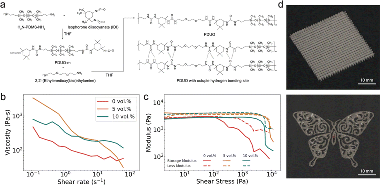
:![[thin space (1/6-em)]](https://www.rsc.org/images/entities/char_2009.gif) 2 was used to make sure the intermediate product (PDUO-m) was terminated by isocyanate groups. After two hours, 0.74 g (5 mmol) of 2,2′-(ethylenedioxy)bis(ethylamine) and glass fibers (0, 5, or 10 vol%) were added to the solution. The chemical structure of the monomers and the formulation process are shown in Fig. 1a. The solution was then thoroughly mixed using a vacuum mixer (FlackTek) and THF was evaporated during this process. As part of the DIW ink preparation, the solvent evaporation process is accelerated (relative to solvent evaporation in casting processes), mostly completing during the vacuum mixing process before printing. Since viscosity increases with the volume fraction of glass fibers, a higher amount of solvent is left in the material for increased volume fractions, in order to maintain printability. Hence, the required mixing time (and associated solvent evaporation) decreases as a function of volume fraction of glass fibers. These were 8 min (0 vol%), 6 min (5 vol%), and 4 min (10 vol%) at 1650 rpm. The amount of THF evaporated was quantified by measuring the total weight loss during the mixing process. 40 mL (0 vol%), 30 mL (5 vol%), and 20 mL (10 vol%) of THF was evaporated in each batch, at which point the rheology of the ink was suitable for DIW printing. The material was finally transferred into a syringe and centrifuged for only a few seconds to remove air bubbles while avoiding stratification.
2 was used to make sure the intermediate product (PDUO-m) was terminated by isocyanate groups. After two hours, 0.74 g (5 mmol) of 2,2′-(ethylenedioxy)bis(ethylamine) and glass fibers (0, 5, or 10 vol%) were added to the solution. The chemical structure of the monomers and the formulation process are shown in Fig. 1a. The solution was then thoroughly mixed using a vacuum mixer (FlackTek) and THF was evaporated during this process. As part of the DIW ink preparation, the solvent evaporation process is accelerated (relative to solvent evaporation in casting processes), mostly completing during the vacuum mixing process before printing. Since viscosity increases with the volume fraction of glass fibers, a higher amount of solvent is left in the material for increased volume fractions, in order to maintain printability. Hence, the required mixing time (and associated solvent evaporation) decreases as a function of volume fraction of glass fibers. These were 8 min (0 vol%), 6 min (5 vol%), and 4 min (10 vol%) at 1650 rpm. The amount of THF evaporated was quantified by measuring the total weight loss during the mixing process. 40 mL (0 vol%), 30 mL (5 vol%), and 20 mL (10 vol%) of THF was evaporated in each batch, at which point the rheology of the ink was suitable for DIW printing. The material was finally transferred into a syringe and centrifuged for only a few seconds to remove air bubbles while avoiding stratification.
2.3 DIW printing
DIW printing was conducted with a customized pneumatically-controlled DIW printer. The samples were printed using a nozzle with an inner diameter of 410 μm, a translation speed of 40 mm s−1, and a pressure of 40 psi. Ideal printability of DIW inks generally requires that the inks are shear thinning and possesses a viscoeleastic yield stress. The rheological characteristics of the inks were measured using a commercial rheometer (TA Instruments Discovery HR 20), with results provided in Fig. 1b and c. As the data show, all inks are shear thinning and exhibit a yield stress, though the yield is sharper for inks with glass fibers than it is for those without (i.e., the moduli drop very quickly over a small range of shear stress), as shown in Fig. 1c. In practice, a sharper yield tends to facilitate 3D printability. During extrusion, the shear stress between the material and the nozzle wall aligns the fibers, aligning fibers along the print path (Fig. S1, ESI†). Fig. 1d shows structures printed with this technique, including a square lattice and a butterfly.2.4 Mechanical testing
Printed samples were ready to be mechanically tested after one night of solvent evaporation. Mechanical tests were conducted using an Instron 68SC-5 mechanical test system. Tests were performed in displacement control at a strain rate of 0.02 s−1. Tensile tests were conducted with a tensile specimen with gauge length of 40 mm, width of 10 mm, and thickness of 0.4 mm. Fracture tests were conducted with thin strip-like specimens with width of 40 mm and height of 20 mm. The specimens were gripped using a screw action grip using a 150 mm by 75 mm jaw face.3 Results and discussion
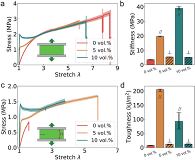
We fabricated 3D printable PDUO at three different volume fractions of glass fibers: 0 vol% (i.e., PDUO with no fibers), 5 vol%, and 10 vol%. We first report the uniaxial stress-stretch responses of the printed materials in the direction parallel to the fiber alignment (shortened as ‖), as shown in Fig. 2a. Without fibers, the 3D-printed PDUO exhibits a uniaxial response similar to prior work,24 with a stiffness of 4 MPa and a stretchability up to 9 times its original length. With the addition of glass fibers, the stiffness of the composites increases significantly (up to 40 MPa), as shown in Fig. 2b. Importantly, strong anisotropy is created in the mechanical response of the composites due to the alignment of the fibers at both volume fractions (Fig. S1, ESI†). When loaded perpendicular to the fiber alignment, the composites behave similarly to the matrix material (Fig. S3, ESI†), regardless of the volume fraction of the fibers. In contrast, when loaded parallel with the fibers, the composites exhibit a stress instability (zero or negative stiffness) around a stretch of 1.15, where there is significant softening for the 5 vol% case. This behavior is consistent with that of conventional PDMS-GF composites, the result of fiber matrix debonding in the gauge region.21 However, at higher volume fractions (10 vol%), the PDUO-GF composites still show this instability, whereas conventional PDMS-GF composites do not. A larger fraction of glass fibers produces more stress concentration after fiber-matrix debonding.25 At these larger volume fractions, conventional PDMS composites fail at very low stretch,21 due to the low toughness of a conventional PDMS matrix. In contrast, this effect does not dominate the stretchability of the PDUO-GF composites, since PDUO is an extremely tough matrix. After the instability, all composites converge to the uniaxial response of PDUO at a stretch close to 3 times the original length. Nevertheless, the presence of fibers still reduces the stretchability of the composites relative to pure PDUO matrix (though they are still able to stretch up to 6 times the original length before failure). The PDUO-GF composites are rate-dependent, as shown in Fig. S4 (ESI†). However, at the practical loading rates we are interested in for typical applications in robotics and devices (few percent per second), this behavior does not have a significant effect. Besides these rate-specific tests, all other mechanical tests in this work were conducted at 0.02 s−1. In addition to uniaxial loading, we also characterized the reloading behavior of the PDUO-GF composites, finding that the material is extremely hysteretic, with a large drop in initial stiffness as increasing stretch is applied to the composites (beyond the previous cycle). Details are shown in Fig. S5 (ESI†).Next, we characterize the toughness of the 3D-printed PDUO and PDUO-GF composites by conducting tensile tests of samples with a pre-cut notch (Fig. 2c). We calculate the toughness G of the material by quantifying the strain energy of the material ahead of the crack when it propagates. This is expressed as G = W(λc)H, where W is the strain energy density (measured using unnotched specimens) up to critical stretch λc, and H is the height of the notched specimens.11,26 Pre-cut PDUO specimens without glass fibers fail at a stretch of λc = 1.50, corresponding to a toughness of around 8000 J m−2, as illustrated in Fig. 2d, slightly lower than the measurements in previous work.24 When loaded perpendicular to the fiber alignment, the toughness of the composites is comparable to the matrix material, as shown in Fig. 2d (i.e., the matrix toughness dominates the response when the composite is loaded perpendicular to the direction of fiber alignment, similar to what was observed for stiffness). PDUO-GF composites actually have much higher toughness when loaded parallel to the fiber alignment, driven by the very large critical stretch accommodated by the matrix. PDUO-GF composites with 5 vol% have a critical stretch similar to the stretch of rupture (stretch at which unnotched samples fail, which is near six times its original length). This leads to significant improvement in toughness of the composites (up to 2![[thin space (1/6-em)]](https://www.rsc.org/images/entities/char_2009.gif) 00
00![[thin space (1/6-em)]](https://www.rsc.org/images/entities/char_2009.gif) 000 J m−2), as shown in Fig. 2d. At 10 vol%, the critical stretch of the composites is not as large as it is for 5 vol%, yet still sufficiently large (λc ∼ 4) to significantly increase the toughness relative to the matrix material (i.e., 1
000 J m−2), as shown in Fig. 2d. At 10 vol%, the critical stretch of the composites is not as large as it is for 5 vol%, yet still sufficiently large (λc ∼ 4) to significantly increase the toughness relative to the matrix material (i.e., 1![[thin space (1/6-em)]](https://www.rsc.org/images/entities/char_2009.gif) 00
00![[thin space (1/6-em)]](https://www.rsc.org/images/entities/char_2009.gif) 000 J m−2vs. 8000 J m−2). At higher volume fractions, composites can fail at smaller values of stretch as a result of higher stress concentrations in the matrix material between fibers.25 This is also consistent with our previous observations for PDMS-GF composites.23
000 J m−2vs. 8000 J m−2). At higher volume fractions, composites can fail at smaller values of stretch as a result of higher stress concentrations in the matrix material between fibers.25 This is also consistent with our previous observations for PDMS-GF composites.23
The extreme toughness of the composite is an order of magnitude higher than that of the matrix material. Since glass is very brittle (toughness around 10 J m−2), the toughness of the composites is beyond the rule of mixtures, implying that there is a synergistic effect arising from the combination of fibers with PDUO. The high toughness calculated in Fig. 2d is a direct result of the large critical stretch, which prevents catastrophic failure even in the presence of a pre-cut crack. This large critical stretch is associated with crack deflection during loading of the notched samples. We monitor the surface of the composite while samples are fractured. A representative stress-stretch curve of notched PDUO-GF with 5 vol% is shown in Fig. 3a. Video is recorded simultaneously with the mechanical tests. Images of the samples at specific stretch levels (indicated on the stress-stretch curve) are shown in Fig. 3b. Immediately after the initial yielding (λ1 = 1.2), local whitening is observed as fringes near the crack tip. Note, this is not observed when fibers are not included in the matrix, as shown in Fig. S6 (ESI†). Such fringes are a result of fiber-matrix debonding, as previously observed in PDMS-GF composites. The whitening is a result of light refraction in voids generated from fiber-matrix debonding, resulting in localized deformation (as observed with digital image correlation21). At small stretch (λ1 = 1.08) prior to the instability observed in unnotched samples, a small region ahead of the crack tip whitens, resembling a plastic region where yielding has occurred. At a stretch of λ2 = 1.20, the whitening region spans the entire crack tip opening. Far away from the crack tip, where the material is mostly experiencing a uniaxial load, localized whitening is observed scattered throughout the width ahead of the crack tip. At further stretch (λ3 = 1.60), most of the material ahead of the crack tip has whitened. Meanwhile, the crack deflects perpendicular to the original notch direction, in both directions, rather than propagating forward. At a stretch of λ4 = 2.00, the deflected crack continues to propagate in the vertical direction while the entire region ahead of the crack tip has whitened, indicating nearly uniform fiber-matrix debonding throughout the material.
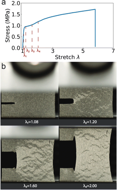 | ||
| Fig. 3 (a) Representative stress-stretch behavior of notched PDUO-GF composites with 5 vol% fibers. (b) Optical images of the deformation of the sample at indicated stretch levels (video of the test can be found in ESI† Movie S1). | ||
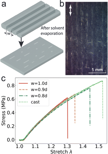
The crack deflection observed in the PDUO-GF composites is associated with the ability of the composites to withstand large loads without failing catastrophically, improving the critical stretch which is directly related to toughness. The fibers are much stiffer than the matrix material PDUO, which favors crack deflection.27 In addition to this large elastic contrast, interfilament defects can also encourage crack deflection.28 For example, the solvents required to print the PDUO-GF ink result in the formation of small bubbles as they evaporate. The solvents evaporate during printing, as illustrated in Fig. 4a, particularly causing defects in the interfilament interstices (Fig. 4b). Hence, we wanted to confirm whether the interfilament defects were contributing to the crack deflection. We printed PDUO specimens with no glass fibers, varying the normalized width w (i.e., interfilament spacing normalized by nozzle diameter d). Smaller w leads to closer packing of materials and fewer large defects. The stress-stretch response of notched specimens is shown as a function of w in Fig. 4c, together with a cast PDUO specimen for comparison. The cast PDUO has the highest critical stretch. Specimens with smaller w fail at larger stretches. However, We do not observe any crack deflection during fracture testing of 3D-printed PDUO. Hence, we can conclude that crack deflection observed from PDUO-GF composites is not the result of printing defects, but rather of the glass fibers. The authors that developed PDUO discussed the effect of microphase separation on the toughness of the material.24 These microphases have length scales on the order of nanometers, three orders of magnitude smaller than the diameter of the glass fibers (micrometers). Hence, the additional toughening observed in these composites can be attributed to the synergistic effect of toughening across multiple length scales.
Finally, we summarize the properties of 3D-printed PDUO and PDUO-GF composites in Fig. 5. Fig. 5a shows that the 3D-printed PDUO-GF composites possess an unprecedented combination of toughness and stiffness, with comparable stiffness to skin but an order of magnitude higher toughness. Moreover, in this work, we focused on properties of unidirectional aligned composites. However, using DIW to build materials with more complex, spatially-varying fiber alignment has the potential to increase the toughness even further.23 In Fig. 5b, we plot toughness vs. stretchability for various tough materials. Early work on tough hydrogels showed that they can be stretched up to 12 times by controlling the ratio of a sacrificial network, though this comes at the loss of toughness. Similarly, stretchability of double network elastomers can be tuned but still is less than the pristine elastomer network.29 By adding glass fibers in PDMS, we also see significant improvement in toughness at a cost of the stretchability. However, by starting with an extremely tough matrix, the 3D printed PDUO-GF composites can be tough and stretchable simultaneously, again reaching a previously unoccupied material space.
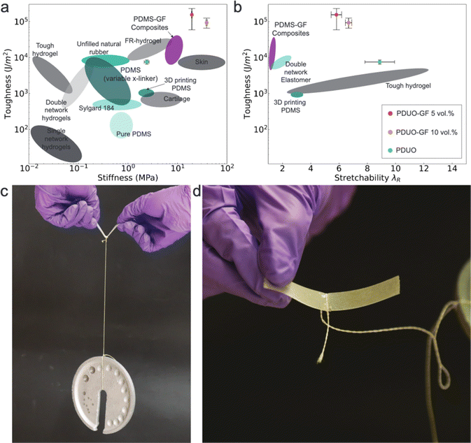 | ||
| Fig. 5 (a) Toughness vs. stiffness for PDUO composites in this work compared to existing engineered soft materials and natural materials such as skin and cartilage. (b) Toughness vs. stretchability for PDUO composites in this work compared to other soft materials, such as tough hydrogels,11 double network elastomers,29 and PDMS composites.23 (c) A photograph showing a thin strip of PDUO-GF composite with a pre-cut crack bearing load (450 g) through a thin strand. (d) A photograph of the thin strip after bearing the load in (c), showing that no crack has grown. | ||
Combining high stiffness, toughness, and stretchability, the PDUO-GF composites can be utilized in various application as load bearing structures. In Fig. 5c, we demonstrate the ability for a thin strip of material to carry weight (450 g). The weight is tied to the strip by a small string. The material has a small pre-cut crack, as illustrated in the zoomed in image (Fig. 5d). After bearing the weight, the crack has not extended and no damage can be observed.
4 Conclusions
We have developed a process for 3D printing tough silicone elastomer composites, i.e., PDMS with octuple hydrogen bonding (PDUO) combined with short glass fibers. The DIW process used to 3D print these materials produces unidirectionally aligned glass fiber-reinforced soft composites. The composites are shown to be extremely tough (one order of magnitude higher in toughness than the matrix material) and highly stretchable. The combination of toughness, stiffness, and stretchability for this composite is unprecedented, making this printable material an excellent candidate for structural materials in extreme soft material applications such as soft robotics.Author contributions
Conceptualization-Chengyang Mo, Jordan R. Raney, methodology-Chengyang Mo, Rui Yin, Data Curation-Chengyang Mo, Rui Yin, writing-draft-Chengyang Mo, Rui Yin, writing-edit-Jordan R. Raney.Conflicts of interest
There are no conflicts to declare.Acknowledgements
The authors gratefully acknowledge the support of the Air Force Office of Scientific Research (award number FA9550-19-1-0285) and NSF via the University of Pennsylvania Materials Research Science and Engineering Center (MRSEC DMR-1720530). The authors also thank Bryan Torres for assistance with rheological experiments.Notes and references
- B. Mosadegh, P. Polygerinos, C. Keplinger, S. Wennstedt, R. F. Shepherd, U. Gupta, J. Shim, K. Bertoldi, C. J. Walsh and G. M. Whitesides, Adv. Funct. Mater., 2014, 24, 2163–2170 CrossRef CAS.
- M. Wehner, R. L. Truby, D. J. Fitzgerald, B. Mosadegh, G. M. Whitesides, J. A. Lewis and R. J. Wood, Nature, 2016, 536, 451–455 CrossRef CAS PubMed.
- W. Hu, G. Z. Lum, M. Mastrangeli and M. Sitti, Nature, 2018, 554, 81–85 CrossRef CAS PubMed.
- G. Li, X. Chen, F. Zhou, Y. Liang, Y. Xiao, X. Cao, Z. Zhang, M. Zhang, B. Wu, S. Yin, Y. Xu, H. Fan, Z. Chen, W. Song, W. Yang, B. Pan, J. Hou, W. Zou, S. He, X. Yang, G. Mao, Z. Jia, H. Zhou, T. Li, S. Qu, Z. Xu, Z. Huang, Y. Luo, T. Xie, J. Gu, S. Zhu and W. Yang, Nature, 2021, 591, 66–71 CrossRef CAS PubMed.
- J. A. Rogers, T. Someya and Y. Huang, Science, 2010, 327, 1603–1607 CrossRef CAS PubMed.
- M. Choi, M. Humar, S. Kim and S.-H. Yun, Adv. Mater., 2015, 27, 4081–4086 CrossRef CAS PubMed.
- H. Yuk, T. Zhang, S. Lin, G. A. Parada and X. Zhao, Nat. Mater., 2016, 15, 190–196 CrossRef CAS.
- C. Yang and Z. Suo, Nat. Rev. Mater., 2018, 3, 125–142 CrossRef CAS.
- N. Fleck, K. Kang and M. Ashby, Acta Metall. Mater., 1994, 42, 365–381 CrossRef CAS.
- Z. Wang, C. Xiang, X. Yao, P. Le Floch, J. Mendez and Z. Suo, Proc. Natl. Acad. Sci. U. S. A., 2019, 116(13), 5967–5972 CrossRef CAS.
- J.-Y. Sun, W. R. K. Illeperuma, X. Zhao, D. J. Mooney, J. J. Vlassak, O. Chaudhuri, Z. Suo and K. H. Oh, Nature, 2012, 489, 133–136 CrossRef CAS PubMed.
- S. Lin, C. Cao, Q. Wang, M. Gonzalez, J. E. Dolbow and X. Zhao, Soft Matter, 2014, 10, 7519–7527 RSC.
- D. R. King, T. L. Sun, Y. Huang, T. Kurokawa, T. Nonoyama, A. J. Crosby and J. P. Gong, Mater. Horiz., 2015, 2, 584–591 RSC.
- Y. Huang, D. R. King, W. Cui, T. L. Sun, H. Guo, T. Kurokawa, H. R. Brown, C. Y. Hui and J. P. Gong, J. Mater. Chem. A, 2019, 7, 13431–13440 RSC.
- R. Takahashi, T. L. Sun, Y. Saruwatari, T. Kurokawa, D. R. King and J. P. Gong, Adv. Mater., 2018, 30, 1–7 CrossRef PubMed.
- D. R. King, T. Okumura, R. Takahashi, T. Kurokawa and J. P. Gong, ACS Appl. Mater. Interfaces, 2019, 11, 35343–35353 CrossRef CAS.
- B. G. Compton and J. A. Lewis, Adv. Mater., 2014, 26, 5930–5935 CrossRef CAS PubMed.
- S. Malek, J. R. Raney, J. A. Lewis and L. J. Gibson, Bioinspiration Biomimetics, 2017, 12, 026014 CrossRef.
- A. Sydney Gladman, E. A. Matsumoto, R. G. Nuzzo, L. Mahadevan and J. A. Lewis, Nat. Mater., 2016, 15, 413–418 CrossRef CAS PubMed.
- Y. Jiang, L. M. Korpas and J. R. Raney, Nat. Commun., 2019, 10, 128 CrossRef PubMed.
- C. Mo, Y. Jiang and J. R. Raney, J. Mech. Phys. Solids, 2020, 141, 103973 CrossRef CAS.
- J. R. Raney, B. G. Compton, J. Mueller, T. J. Ober, K. Shea and J. A. Lewis, Proc. Natl. Acad. Sci. U. S. A., 2018, 115, 1198–1203 CrossRef CAS PubMed.
- C. Mo, H. Long and J. R. Raney, Proc. Natl. Acad. Sci. U. S. A., 2022, 119(28), e2123497119 CrossRef CAS PubMed.
- Y. Zhuo, Z. Xia, Y. Qi, T. Sumigawa, J. Wu, P. Šesták, Y. Lu, V. HÅkonsen, T. Li, F. Wang, W. Chen, S. Xiao, R. Long, T. Kitamura, L. Li, J. He and Z. Zhang, Adv. Mater., 2021, 33, 2008523 CrossRef CAS.
- L. A. Goettler and K. S. Shen, Rubber Chem. Technol., 1983, 56, 619–638 CrossRef CAS.
- R. S. Rivlin and A. G. Thomas, J. Polym. Sci., 1953, 10, 291–318 CrossRef CAS.
- M.-Y. He and J. W. Hutchinson, Int. J. Solids Struct., 1989, 25, 1053–1067 CrossRef.
- C. Mo and J. R. Raney, Extreme Mech. Lett., 2020, 34, 100598 CrossRef.
- E. Ducrot, Y. Chen, M. Bulters, R. P. Sijbesma and C. Creton, Science, 2014, 344, 186–189 CrossRef CAS.
Footnote |
| † Electronic supplementary information (ESI) available. See DOI: https://doi.org/10.1039/d2sm00923d |
| This journal is © The Royal Society of Chemistry 2022 |

