 Open Access Article
Ni–rGO–zeolite nanocomposite: an efficient heterogeneous catalyst for one-pot synthesis of triazoles in water†
Prasun
Choudhury
 a,
Shreyasi
Chattopadhyay‡
 b,
Goutam
De§
 *bc and
Basudeb
Basu¶
 *ad
*ad
aDepartment of Chemistry, North Bengal University, Darjeeling 734013, India. E-mail: basu_nbu@hotmail.com
bCSIR-Central Glass & Ceramic Research Institute, 196, Raja S. C. Mullick Road, Jadavpur, Kolkata 700032, India
cS. N. Bose National Centre for Basic Sciences, Block – JD, Sector – III, Salt Lake, Kolkata 700106, India. E-mail: g.de@bose.res.in
dRaiganj University, Raiganj 733134, India
First published on 19th March 2021
Abstract
An important group of pharmaceutical materials, 1,2,3-triazoles, has been synthesised using a Ni-based nanocomposite catalyst (Ni–rGO–zeolite) through azide alkyne cycloaddition (NiAAC). First, a GO–zeolite hybrid was prepared through protonation of a Na–Y–zeolite by H+ ions originating from the –COOH groups of GO. Subsequently the GO–zeolite was treated with Ni-acetate solvothermally in the presence of NaBH4 (reducing atmosphere). Under the solvothermal conditions a significant part of the incorporated Ni ions in the GO–zeolite were reduced to Ni(0) and simultaneously GO was transformed into rGO. The resulting ternary nanocomposite, Ni–rGO–zeolite, serves as a highly efficient heterogeneous catalyst, and shows excellent regioselectivity forming 1,4-disubstituted-1,2,3-triazoles as the sole product at a low loading of the nickel (∼2.6 mol% with respect to the substrate) with recyclability, and without any significant leaching of the metal. In addition, the Ni–rGO–zeolite exhibits enhanced efficiency under aqueous conditions, proficiency with varying substrates and overcomes some of the shortcomings of the previously reported limited number of Ni-based and other catalysts. The catalytic process is believed to involve the active Ni(0) species, which is stabilized by electron rich rGO that is supported on the microporous high-surface-area zeolite.
1. Introduction
The 1,2,3-triazoles represent an important class of five-membered heterocyclic compounds and they find widespread applications in pharmaceutical, biological chemistry, and drug delivery research.1–3 The copper(I) catalysed [3+2] cycloaddition (CuAAC) reaction between a terminal alkyne and an alkyl azide, commonly known as the ‘click reaction’, provides easy access to the regioselective synthesis of 1,4-disubstituted-1,2,3-triazoles.4 A wide variety of copper catalysts, both homogeneous and heterogeneous forms, have been developed and successfully employed in CuAAC reactions.5,6 Although copper is cheap and less toxic than many other transition metals, it has some drawbacks in the CuAAC reaction. For example, the intermediate Cu-acetylide tends to polymerize and forms a dinuclear Cu intermediate, eventually affecting the rate of the reaction and the yield of the cycloadduct.7–10 Moreover, the use of Cu(II) species often requires a reducing agent making the process less atom-economic. Other transition metals like Ru, Rh, Ag, Au, Ir and Zn have also been used as catalysts in AAC,10–12 though their efficacy is limited in terms of the regioselectivity of the product, general applicability, use of precious metals/ligands and tricky procedure for making the catalytic systems.The nickel (Ni) catalyzed azide alkyne [3+2] cycloaddition (NiAAC) has rarely been explored and literature reports reveal only a few Ni-based catalysts used in the AAC.13–16 While the use of Raney® nickel leads to both 1,4- and 1,5-disubstituted cyclo-adducts,13 the alternative ligand-specific and expensive catalytic system (Cp2Ni-Xantphos) can be used for both terminal and internal alkynes, preferentially forming 1,5-disubstituted triazoles.14,15 Moreover, the actual catalyst in this case is Ni(Xantphos)2, which is generated in situ and is not recoverable.15 Another heterogeneous Ni catalyst is based on the triazole linked organic polymer (Ni-TLOP), which acts as a photocatalyst in AAC under visible light induced conditions.16 The Ni-TLOP catalyst exhibits a high catalytic performance in AAC, however, preparation of the catalyst requires expensive chemicals, and the catalyst becomes active only under visible light irradiation, as studied in a two-component AAC process. We have previously prepared a Ni catalyst supported on reduced graphene oxide (Ni–rGO) and investigated catalytic performance in C–C and C–S cross coupling reactions.17,18 Although the rGO surface is rich with a π-electron network for stabilization of the Ni(0) species, we did observe the formation of Ni(II) species being immobilized after the catalytic C–S coupling reaction.18 Exploring the catalytic performance of Ni–rGO in azide alkyne cycloaddition, however, afforded a poor yield of the cycloadduct (∼40%). Microporous zeolites are very attractive for applications as a catalyst,19 and as support materials for anchoring metal nanoparticles and subsequent catalytic functions.20 Several unique properties like high surface area, intrinsic nano-sized pore cavities with sub-nano pore openings, easy mass transport properties and also hydrothermal stability make them a versatile host material. We have also prepared Ni–zeolite following the reported procedure,21 and examined its catalytic performance in three-component AAC. However, the yield of the cycloadduct obtained was only about 52%.
We envisioned that Ni(0) NPs being supported in the high surface area rGO–zeolitic hybrid with a π-electron rich surface could be more useful for the stabilization and subsequent catalytic efficiency of the Ni(0) species. It is known that zeolites consist of a tetrahedral structure with (AlO4)5− and (SiO4)4− species, and formal protonation can balance the negative charge resulting hydroxyl bridging (Al–OH–Si), which could serve as the Brønsted acid sites.19 Again, metal-doped zeolites can have Lewis acidic sites, and tangible synergistic effects of Brønsted–Lewis acidic sites of protonated and metal-doped zeolites could be expected for efficient catalytic applications.20
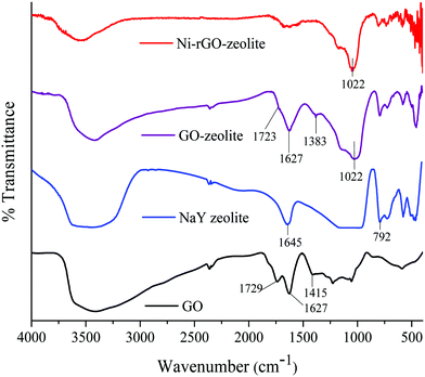
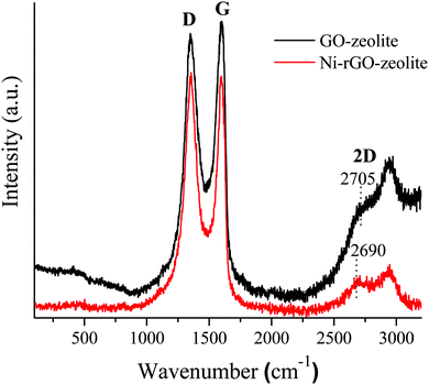
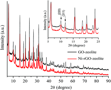
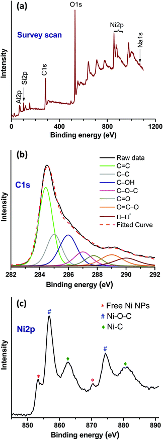
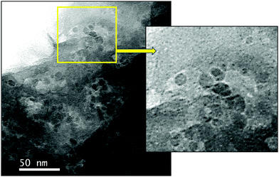
Based on above discussions and considering that graphene oxide (GO) with its peripheral carboxylic acid groups could act as the proton source, we first mixed an aqueous dispersion of GO with NaY zeolite in water to obtain the GO–zeolite hybrid material. Then the hybrid GO–zeolite was treated with nickel(II) salts under reducing conditions to prepare a ternary nanocomposite preferentially with the Ni(0) oxidation state. Characterizations of the material by FT-IR, powder XRD and XPS revealed that the hybrid GO–zeolite is transformed in situ to rGO–zeolite anchored with nickel during the impregnation of nickel under reducing conditions to afford the ternary nanocomposite, designated as the Ni–rGO–zeolite. This nanocomposite material, having highly dispersed atomic level active Ni co-hosted by rGO–zeolite is examined as a heterogeneous catalyst in the AAC.
We found that the present heterogeneous catalytic system offers certain advantages, such as easy preparation from cheap and sustainable materials, stability at room temperature, high catalytic efficiency in aqueous medium, regioselective formation of 1,4-disubstituted-1,2,3-triazoles, recovery by simple filtration and recyclability. As compared with previously reported very limited number of homo- and heterogeneous Ni-based catalysts used in the AAC,13–16 the present catalytic process using Ni–rGO–zeolite follows three-component cycloaddition, which is more advantageous over the two-component cycloaddition process because the former avoids an extra step of making unstable organyl azides (Scheme 1).
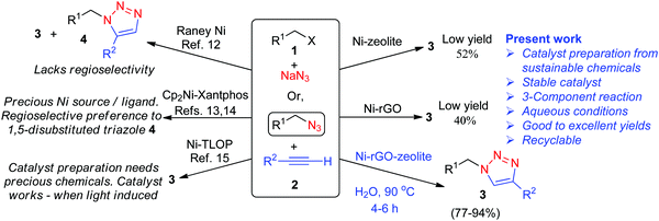 | ||
| Scheme 1 Comparative scheme for various Ni-catalysed azide alkyne cycloadditions either in two- or three-component processes. | ||
2. Results and discussion
2.1. Preparation of Ni–rGO–zeolite nanocomposite
We first prepared a hybrid GO–zeolite from 2D GO and the NaY zeolite (faujasite). The GO–zeolite composite was prepared by adding sodium Y (NaY) zeolite to an aqueous suspension (pH ≈ 11.2) to an aqueous dispersion of GO (pH ≈ 3.4). Addition of the zeolite to the acidic GO solution (where the acid source originates from the carboxylic acid groups associated with GO) increases the pH close to 7 due to protonation. Such protonation balances the negative charges on the zeolite resulting in hydroxyl bridging (Al–OH–Si), which could serve as the Brønsted acid sites. This protonation reaction also helps the formation of a uniform GO–zeolite hybrid. The reaction mixture was then heated at 60 °C for 16 h under gentle magnetic stirring followed by evaporation of water and drying under vacuum to afford the GO–zeolite composite. The GO–zeolite (suspended in ethylene glycol) was subsequently treated with nickel species (Ni(OAc)2·4H2O) in the presence of NaBH4 under hydrothermal conditions. Under these reaction conditions the in situ reduction of GO to rGO and Ni(2+) to Ni(0) occurs, and the ternary nanocomposite material Ni–rGO–zeolite is formed (see Experimental section for details). The ternary nanocomposite material has been characterized using various spectroscopic and microscopic techniques.2.2. Characterization of Ni–rGO–zeolite nanocomposite
![[double bond, length as m-dash]](https://www.rsc.org/images/entities/char_e001.gif) O and C
O and C![[double bond, length as m-dash]](https://www.rsc.org/images/entities/char_e001.gif) C bonds respectively.22 The broad peak at around 3432 cm−1 was related to the stretching vibration of the hydroxyl groups present in GO.22 In the case of the GO–zeolite and the Ni–rGO–zeolite, the peaks at 1022, 578 and 454 cm−1 were due to the internal vibrations of the TO4 (T = Si, Al) tetrahedral moiety of the NaY zeolite.23 Moreover, the disappearance of the typical carbonyl band at 1729 cm−1 indicates that the carbonyl groups might have been converted to Al/Si–O–C bonds resulting in the formation of the nanocomposite.24
C bonds respectively.22 The broad peak at around 3432 cm−1 was related to the stretching vibration of the hydroxyl groups present in GO.22 In the case of the GO–zeolite and the Ni–rGO–zeolite, the peaks at 1022, 578 and 454 cm−1 were due to the internal vibrations of the TO4 (T = Si, Al) tetrahedral moiety of the NaY zeolite.23 Moreover, the disappearance of the typical carbonyl band at 1729 cm−1 indicates that the carbonyl groups might have been converted to Al/Si–O–C bonds resulting in the formation of the nanocomposite.24
![[double bond, length as m-dash]](https://www.rsc.org/images/entities/char_e001.gif) C (284.42 eV) and C–C (285.08 eV) arising from rGO. In addition, peaks at 285.90, 287, 287.75 and 289 eV indicated the presence of C–OH, C–O–C, C
C (284.42 eV) and C–C (285.08 eV) arising from rGO. In addition, peaks at 285.90, 287, 287.75 and 289 eV indicated the presence of C–OH, C–O–C, C![[double bond, length as m-dash]](https://www.rsc.org/images/entities/char_e001.gif) O and O
O and O![[double bond, length as m-dash]](https://www.rsc.org/images/entities/char_e001.gif) C–O functional groups on rGO, respectively.28 Moreover, the peak appearing at 286.50 eV can be attributed to the Ni–C bonding. The Ni2p high resolution spectrum shows the Ni2p1/2 and Ni2p3/2 core-level signals (Fig. 4c). In this spectrum, the existence of the Ni2p3/2 and Ni2p1/2 core-level peaks at 853.17 and 870.54 eV, respectively, corresponds to the free metallic Ni(0).29,30 The pair of binding energy peaks at 856.95 (Ni2p3/2) and 874.46 (Ni2p1/2), and 862.68 eV (Ni2p3/2) and 880.80 eV (Ni2p1/2) can be assigned to Ni–O–C and Ni–C bonds, respectively.29,30 Therefore, the XPS results confirmed the existence of the intrinsic interaction between the rGO and Ni moieties.
C–O functional groups on rGO, respectively.28 Moreover, the peak appearing at 286.50 eV can be attributed to the Ni–C bonding. The Ni2p high resolution spectrum shows the Ni2p1/2 and Ni2p3/2 core-level signals (Fig. 4c). In this spectrum, the existence of the Ni2p3/2 and Ni2p1/2 core-level peaks at 853.17 and 870.54 eV, respectively, corresponds to the free metallic Ni(0).29,30 The pair of binding energy peaks at 856.95 (Ni2p3/2) and 874.46 (Ni2p1/2), and 862.68 eV (Ni2p3/2) and 880.80 eV (Ni2p1/2) can be assigned to Ni–O–C and Ni–C bonds, respectively.29,30 Therefore, the XPS results confirmed the existence of the intrinsic interaction between the rGO and Ni moieties.
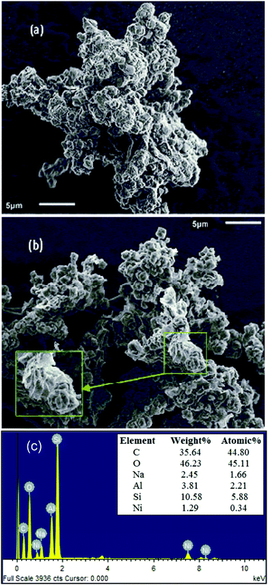 | ||
| Fig. 5 SEM images of (a) GO–zeolite, (b) Ni–rGO–zeolite, and (c) representative EDS spectrum of Ni–rGO–zeolite, elemental composition is shown in the inset (average values of 3 sets of EDS data). | ||
3. Catalytic activity of Ni–rGO–zeolite nanocomposite
3.1. Catalytic activity
In order to evaluate the catalytic activity of this newly developed ternary nanocomposite (Ni–rGO–zeolite) in a three-component azide–alkyne ‘click’ reaction for the synthesis of triazole moieties, we examined the combination of benzyl bromide (1a), phenylacetylene (2a) and sodium azide as the model reactants, and the results are presented in Table 1. As described above, we carried out the reaction using the heterogeneous catalytic systems Ni–rGO and Ni–zeolite in aqueous medium at 90 °C (entries 1 and 2), which gave the desired cycloadduct in 40% and 52% yields, respectively. The use of our newly developed catalyst (Ni–rGO–zeolite; 30 mg mmol−1 of benzyl bromide) afforded the product (1-benzyl-4-phenyl-1H-1,2,3-triazole; 3a) in 94% yield under similar conditions (entry 3). Reducing the amount of catalyst to 15 mg however lowered the yield of the product (82%; entry 4). Again, lowering the temperature also gave 3a in 69% yield only (entry 5). When a neat mixture of the reactants and catalyst was used for the reaction, we isolated the product in 77% yield (entry 6). We also performed the reaction in the presence of an additive, tetrabutylammonium bromide (TBAB, 10 mol%), but observed a fairly similar result (95%; entry 7). We also checked the viability of the catalytic reaction in organic solvent (CH3CN) or in a mixture of CH3CN![[thin space (1/6-em)]](https://www.rsc.org/images/entities/char_2009.gif) :
:![[thin space (1/6-em)]](https://www.rsc.org/images/entities/char_2009.gif) H2O (1
H2O (1![[thin space (1/6-em)]](https://www.rsc.org/images/entities/char_2009.gif) :
:![[thin space (1/6-em)]](https://www.rsc.org/images/entities/char_2009.gif) 1 v/v) at 80 °C, which gave the desired product 3a, respectively, in 67% and 81% yield (entries 8 and 9). We also screened the reaction in organic solvents like methanol (MeOH) and dimethylformamide (DMF), both protic and aprotic polar solvents. While the reaction in MeOH at 90 °C afforded the desired product 3a, in 83% yield (entry 10), the same reaction in DMF at 110 °C for 4 h and 10 h gave 3a in 88% and 90% yield, respectively (entries 11 and 12). The use of the polar aprotic solvent (DMF) gave slightly better conversions over protic MeOH as the solvent, though the prolonged reaction time (10 h) in DMF did not show any significant improvement in terms of yield of the desired product 3a. Further studies with Ni(OAc)2·4H2O as the catalyst (15 mol%) could produce the cycloadduct in 53% yield under similar reaction conditions (entry 13), whereas the reaction conducted in the absence of any catalyst resulted in a meagre conversion (16%; entry 14). This finding suggested the significant role of the Ni catalyst in the three-component [3+2] AAC. Studies under various conditions suggested the optimal conditions were as in entry 3. Finally, we scaled up the reaction under the optimized conditions with a partially lowered loading of the catalyst and that also resulted in a good conversion (entry 15, 89%).
1 v/v) at 80 °C, which gave the desired product 3a, respectively, in 67% and 81% yield (entries 8 and 9). We also screened the reaction in organic solvents like methanol (MeOH) and dimethylformamide (DMF), both protic and aprotic polar solvents. While the reaction in MeOH at 90 °C afforded the desired product 3a, in 83% yield (entry 10), the same reaction in DMF at 110 °C for 4 h and 10 h gave 3a in 88% and 90% yield, respectively (entries 11 and 12). The use of the polar aprotic solvent (DMF) gave slightly better conversions over protic MeOH as the solvent, though the prolonged reaction time (10 h) in DMF did not show any significant improvement in terms of yield of the desired product 3a. Further studies with Ni(OAc)2·4H2O as the catalyst (15 mol%) could produce the cycloadduct in 53% yield under similar reaction conditions (entry 13), whereas the reaction conducted in the absence of any catalyst resulted in a meagre conversion (16%; entry 14). This finding suggested the significant role of the Ni catalyst in the three-component [3+2] AAC. Studies under various conditions suggested the optimal conditions were as in entry 3. Finally, we scaled up the reaction under the optimized conditions with a partially lowered loading of the catalyst and that also resulted in a good conversion (entry 15, 89%).
| Entry | Catalyst (mg) | Solvent | Temp (°C)/time (h) | Yieldb (%) |
|---|---|---|---|---|
| a Reaction conditions: 1a (1 mmol), 2a (1 mmol), NaN3 (1.5 mmol) and solvent (2 mL). b Isolated yield. c Reaction carried out using the Ni–rGO catalytic system (the FT-IR spectrum of Ni–rGO is given in the ESI, Section SI-2.1 and Fig. S1). d Reaction carried out using the Ni–zeolite catalytic system (the FT-IR spectrum of Ni–zeolite is given in the ESI, Section SI-2.2 and Fig. S2). e Reaction carried using Ni–rGO–zeolite. f TBAB (10 mol%) was used. g Ni(OAc)2·4H2O (15 mol%) was used. | ||||
| 1 | 30 | H2O | 90/4 | 40c |
| 2 | 30 | H2O | 90/4 | 52d |
| 3 | 30 | H 2 O | 90/4 | 94 |
| 4 | 15 | H2O | 90/4 | 82 |
| 5 | 30 | H2O | 60/4 | 69 |
| 6 | 30 | — | 90/4 | 77 |
| 7 | 30 | H2O | 90/4 | 95f |
| 8 | 30 | CH3CN | 80/4 | 67 |
| 9 | 30 | CH3CN![[thin space (1/6-em)]](https://www.rsc.org/images/entities/char_2009.gif) : :![[thin space (1/6-em)]](https://www.rsc.org/images/entities/char_2009.gif) H2O (1 H2O (1![[thin space (1/6-em)]](https://www.rsc.org/images/entities/char_2009.gif) : :![[thin space (1/6-em)]](https://www.rsc.org/images/entities/char_2009.gif) 1) 1) |
80/4 | 81 |
| 10 | 30 | MeOH | 90/4 | 83 |
| 11 | 30 | DMF | 110/4 | 88 |
| 12 | 30 | DMF | 110/10 | 90 |
| 13 | Ni(OAc)2·4H2O | H2O | 90/4 | 53g |
| 14 | — | H2O | 80/24 | 16 |
| 15 | 100 | H2O | 90/4 | 89 |
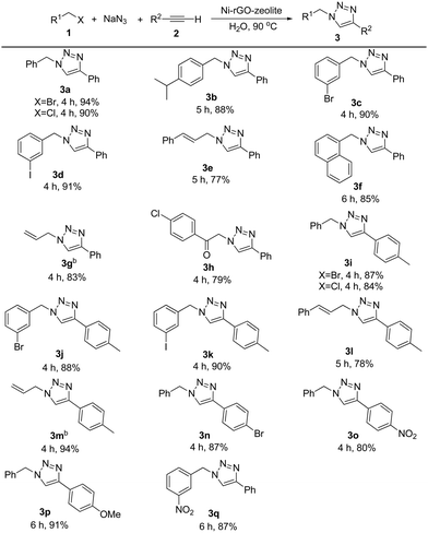
The general applicability of the catalyst was examined with various alkyl halides and terminal alkynes using the optimized conditions (Table 2). Initially, we varied alkyl halides for the reaction, keeping the alkyne fixed. Subsequently, we tested the effect of the substituent on the alkyne partner for the reaction. Both benzyl bromide and benzyl chloride gave the triazole 3a in 94% and 90% isolated yield respectively. Benzyl bromide bearing an isopropyl, bromo or iodo group in the ring reacted efficiently with phenylacetylene affording the desired products (3b–3d) in 88–91% yield. In case of cinnamyl bromide, although the reaction took place affording the triazole 3e, the yield of the product was comparatively low. The lower yield might be due to the tendency of cinnamyl azide to undergo an intramolecular rearrangement.32 Alkyl halide containing the naphthyl group, for example, 1-chloromethyl naphthalene, also reacted under the conditions giving product 3f in 85% yield. A further attempt with allyl bromide also worked smoothly and the desired product 3g was obtained in 83% isolated yield. The reaction involving activated functionalized organic halides, such as 4-chlorophenacyl bromide, was also accomplished. Terminal alkynes other than phenylacetylene, such as 4-ethynyltoluene, 1-bromo-4-ethynylbenzene and 1-ethynyl-4-nitrobenzene, also reacted efficiently. In the reaction between 4-ethynyltoluene and different alkyl halides, under the standard reaction conditions, the corresponding triazoles (3i–3m) were obtained in 78–94% yield. 1-Bromo-4-ethynylbenzene and 1-ethynyl-4-nitrobenzene were also transformed into the corresponding triazoles (3n and 3o) in 87% and 80% yield respectively. We further extended the product library of triazoles bearing strong electron donating (on the alkynyl part) and strong electron withdrawing groups (on the alkyl halide part) and the corresponding triazole products (3p and 3q) were obtained in 91% and 87% isolated yields respectively. Thus the reaction conditions are robust, regioselective and green regardless of the electronic nature and substitution pattern on the alkyl as well as the alkyne moiety. We present a comparative table (Table S1, ESI†) which consists of the catalytic performances (such as loading, general applicability and other aspects) of the present catalytic system, Ni–rGO–zeolite nanocomposite, with reported Ni–, Cu– and other transition metal-based catalysts in the AAC reaction. The comparative table shows the advantages of our catalyst, Ni–rGO–zeolite, as compared with the state-of-the-art reports.
We have reported the preparation of a heterogeneous copper catalyst (Cu2O@ARF) and its application in a three-component azide alkyne cycloaddition reaction.6 We considered that it is worth comparing the relative catalytic performance between the copper catalyst (Cu2O@ARF) and the present catalytic system (Ni–rGO–zeolite). The results show relatively better yields in most of the representative examples in the NiAAC, indicating that suitably designed and stabilized Ni(0) catalysts are quite efficient in three-component azide alkyne cycloaddition giving rise to the regioselective formation of 1,4-disubstituted triazoles (Table S2, ESI†).
3.2. Recyclability of Ni–rGO–zeolite nanocomposite
The recyclability of the Ni–rGO–zeolite catalyst was evaluated in the three-component reaction of 1a, 2a and NaN3 in water under the optimized conditions (Table 1, entry 3). After the first run the catalyst was separated by simple filtration, washed with ethyl acetate (5 × 5 mL) and dried under vacuum for 24 h and was re-used for the second run. In the same process, the catalyst was re-used for four consecutive runs without any significant drop in the yield of the product (Fig. 7). A small drop in yield is due to loss of the catalyst during its isolation after each cycle of reaction. We measured the nickel content in the Ni–rGO–zeolite before and after the recycling runs. As seen from ICP-AES measurements, before the reaction the nickel content in the Ni–rGO–zeolite was 0.887 mmol g−1, whereas after the first and third runs the nickel content was 0.887 mmol g−1, and 0.733 mmol g−1, respectively. This indicates that no significant leaching of nickel occurred from the nanocomposite during the reaction. Detailed characterizations (FT-IR, XRD and Raman) of the Ni–rGO–zeolite catalysts after recycling experiments are given in the ESI† (Section SI-3 and Fig. S3–S5). All these characterizations confirm that the developed nanocomposite catalyst (Ni–rGO–zeolite) is stable after reaction.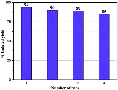 | ||
| Fig. 7 Recycling experiments using the Ni–rGO–zeolite in the click reaction between benzyl bromide, NaN3 and phenylacetylene. | ||
3.3. XPS analysis of the catalyst after the reaction
XPS analysis of the catalyst after the first cycle was carried out to understand any changes in the chemical state of the elements (nickel) (Fig. 8). The survey scan (Fig. 8a) shows that binding energy peaks originating from the rGO, zeolite and Ni were observed. However, in the Ni2p high resolution spectrum, an increase of metallic Ni NPs related peaks was observed (Fig. 8b). As a result, the relative peak intensities of Ni–O–C and Ni–C were decreased. It is noteworthy that, under the reaction conditions, NaN3 has the ability to modify the oxygen containing functional groups of rGO,33 and as such the formation of a greater number of free nickel NPs in the composite after the first cycle of the reaction could be expected. However, the ICP-AES analysis confirmed the retention of the total nickel content in the composite catalyst, and thus no significant loss during catalysis was observed in the subsequent reactions.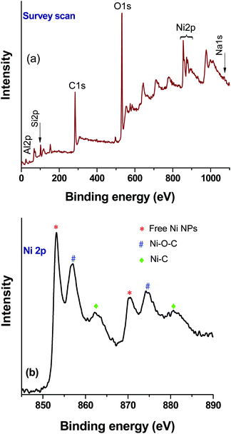 | ||
| Fig. 8 XPS analysis of the Ni–rGO–zeolite composite catalyst after the first run: (a) survey scan and (b) high resolution Ni2p spectrum. | ||
3.4. Plausible mechanism for the reaction
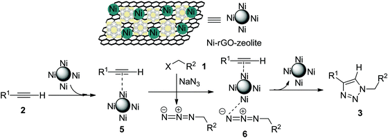
The Cu-catalysed cycloaddition (CuAAC) is believed to involve copper acetylide as one of the key intermediates, which then undergoes cycloaddition with the azide moiety leading to the formation of the triazole (the Sharpless–Meldal version of the CuAAC reaction).7–9 However, Sommer et al. observed that a similar reaction on the CuI–zeolite surface does not involve the Cu–acetylide intermediate and proceeds through the formation of a π-complex between alkyne and the metal ion anchored with the zeolite followed by reaction with the azide and subsequent formation of the triazole.34 When Raney® nickel is used as the catalyst, the AAC reaction (NiAAC) is also believed to occur through π-complexation between the alkyne and nickel followed by cycloaddition with the azide. The author studied the reaction with a terminal deuterated alkyne and obtained the triazole with complete retention of deuterium.13 Based on these observations, we consider that the free nickel NPs, being confined in the zeolitic pores and supported by rGO, could be the active catalyst for the cycloaddition reaction. The first step of the reaction presumably involves a Ni(0) coordinated alkyne species (5), which then coordinates with the in situ generated alkyl azide to form (6) (Scheme 2). The stabilized Ni(0) NPs supported with the rGO–zeolite help to bring the reacting partners closer for undergoing regioselective cycloaddition that leads to the formation of the triazole (3).4. Conclusion
In conclusion, we have developed a new Ni-based ternary nanocomposite material that exhibits excellent catalytic activity in the three-component azide alkyne cycloaddition (NiAAC) in water, leading to the regioselective formation of 1,4-disubstituted 1,2,3-trizole. The heterogeneous catalyst (Ni–rGO–zeolite) is easy to prepare, robust, and recyclable without any significant drop in its performance. The partly enhanced catalytic performance of this heterogeneous Ni catalyst in AAC presumably originates from the concurrent support and stabilization of the active Ni(0) species by a unique combination of microporous zeolitic pores being supported with the π-electron-rich rGO surface. Among the very few Ni catalysts studied in the [3+2] AAC, the present catalytic system not only eliminates some of the shortcomings but will certainly pave the way for further application of Ni-catalysed ‘click’ reactions.5. Experimental section
(see also ESI;† SI-1).5.1. Preparation of graphene oxide (GO)
Graphene oxide was prepared by following Tour's method.22 In this method a 9![[thin space (1/6-em)]](https://www.rsc.org/images/entities/char_2009.gif) :
:![[thin space (1/6-em)]](https://www.rsc.org/images/entities/char_2009.gif) 1 (v/v) mixture of H2SO4/H3PO4 (180
1 (v/v) mixture of H2SO4/H3PO4 (180![[thin space (1/6-em)]](https://www.rsc.org/images/entities/char_2009.gif) :
:![[thin space (1/6-em)]](https://www.rsc.org/images/entities/char_2009.gif) 20 mL) was added to a mixture of graphite powder (1.5 g) and KMnO4 (9.0 g). The mixture was then stirred at 50 °C for 12 h. After cooling the mixture to room temperature, it was gradually poured into crushed ice (200 g), which was followed by the slow addition of H2O2 (30%, 3 mL). The solution was then centrifuged (5000 rpm) and the supernatant was discarded. The residual solid material was successively washed with deionised water (100 mL) and then with 30% HCl (100 mL). The solid material was then repeatedly washed with water and centrifuged. Finally, the solid brown material was collected and dried at 60 °C under vacuum to obtain solid graphene oxide.
20 mL) was added to a mixture of graphite powder (1.5 g) and KMnO4 (9.0 g). The mixture was then stirred at 50 °C for 12 h. After cooling the mixture to room temperature, it was gradually poured into crushed ice (200 g), which was followed by the slow addition of H2O2 (30%, 3 mL). The solution was then centrifuged (5000 rpm) and the supernatant was discarded. The residual solid material was successively washed with deionised water (100 mL) and then with 30% HCl (100 mL). The solid material was then repeatedly washed with water and centrifuged. Finally, the solid brown material was collected and dried at 60 °C under vacuum to obtain solid graphene oxide.
5.2. Preparation of GO–zeolite nanocomposite
Graphene oxide (275 mg) was dispersed in distilled water (100 mL) and ultrasonically treated for 1 h. Subsequently, sodium Y zeolite (400 mg) was steadily added to the GO dispersion to ensure the neutral pH of the overall dispersion. The dispersion was then heated using an oil bath at 60 °C with stirring for 16 h. The solvent was then removed under reduced pressure and the solid mass was dried under vacuum for 24 h.5.3. Preparation of Ni–rGO–zeolite nanocomposite
A Teflon capped sealed tube containing the GO–zeolite (500 mg) dispersion in ethylene glycol (10 mL) was charged with Ni(OAc)2·4H2O (124 mg, 0.5 mmol). The contents were then gently stirred at 60 °C for 30 minutes. After that, NaBH4 (37 mg, 1 mmol) was added to the mixture portion wise. The sealed tube was again Teflon capped and placed in a preheated oil bath at 180 °C. After stirring for 3 h, the mixture was cooled to room temperature, diluted with water and centrifuged at 5000 rpm. The supernatant was discarded and the solid composite material was washed alternatively with water and ethanol (3 times each). The solid composite material was then dried under vacuum for 48 h.5.4. Preparation of Ni–zeolite and Ni–rGO catalysts (control samples)
The Ni–zeolite composite catalyst was prepared using a reported literature method with minor modifications.21 Briefly, a 250 mL RB flask was charged with ethylene glycol (50 mL) and NiNO3·6H2O (290 mg). The mixture was ultrasonicated for 30 min, sealed, purged with nitrogen and placed in an oil bath at 200 °C. This was followed by the rapid addition of NaBH4 (200 mg) into the flask. The mixture was then stirred at this temperature for 2 h before being cooled to room temperature. The solid was separated by centrifugation, washed with ethanol and distilled water (3 times each) and dried under vacuum for 24 h. The other control sample, the Ni–rGO catalyst, was prepared following our previously reported method.18 These catalysts were verified by FT-IR analysis (ESI,† Section SI-2).5.5. General procedure for the synthesis of 1,4-disubstituted-1,2,3-triazole derivatives using Ni–rGO–zeolite catalyst
A round bottomed flask (25 mL) equipped with a magnetic stir bar was charged with alkyl halide (1 mmol), terminal alkyne (1 mmol), NaN3 (1.5 mmol) and the Ni–rGO–zeolite (30 mg). Freshly distilled water (2 mL) was added to it and the reaction mixture was gently stirred at 90 °C for 4–6 h. After completion of the reaction (monitored by TLC), the reaction mixture was cooled to room temperature. The catalyst was recovered through simple filtration and the reaction mixture was extracted using ethyl acetate (3 × 5 mL). The combined organic layer was dried over anhydrous Na2SO4 and concentrated under vacuum. The residue obtained was purified by column chromatography using light petroleum ether/ethyl acetate as the eluent to afford the desired product. All products were characterized by 1H, and 13C-NMR data and were also compared with reported melting points for solid compounds (ESI;† Sections SI-4 and SI-5).Conflicts of interest
There are no conflicts to declare.Acknowledgements
Financial support from SERB, New Delhi is gratefully acknowledged (Grant No EMR/2015/000549). PC and SC thanks UGC, New Delhi, for Senior Research Fellowship under UGC-NET. We would also like to acknowledge University Science and Instrumentation Centre, North Bengal University, for SEM facility.Notes and references
- K. Bozorov, J. Zhao and H. A. Aisa, Bioorg. Med. Chem., 2019, 27, 3511–3531 CrossRef CAS PubMed.
- S. Guernelli, A. Cariola, A. Baschieri, R. Amorati and P. L. Meo, Mater. Adv., 2020, 1, 2501–2508 RSC.
- D. Dheer, V. Singh and R. Shankar, Bioorg. Chem., 2017, 71, 30–54 CrossRef CAS PubMed.
- N. Nebra and J. Garcia-Alvarez, Molecules, 2020, 25, 2015–2033 CrossRef CAS PubMed.
- S. Neumann, M. Biewend, S. Rana and W. H. Binder, Macromol. Rapid Commun., 2020, 41, 1900359 CrossRef CAS PubMed.
- S. Ghosh, S. Saha, D. Sengupta, S. Chattopadhyay, G. De and B. Basu, Ind. Eng. Chem. Res., 2017, 56, 11726–11733 CrossRef CAS.
- R. Chung, A. Vo, V. V. Fokin and J. Hein, ACS Catal., 2018, 8, 7889–7897 CrossRef CAS.
- L. Zhu, C. J. Brassard, X. Zhang, P. M. Guha and R. J. Clark, Chem. Rec., 2016, 16, 1501–1517 CrossRef CAS PubMed.
- B. T. Worell, J. A. Malik and V. V. Fokin, Science, 2013, 340, 457–460 CrossRef PubMed.
- C. Wang, D. Ikhlef, S. Kahlal, J.-Y. Saillard and D. Astruc, Coord. Chem. Rev., 2016, 316, 1–20 CrossRef CAS.
- M. A. Morozova, M. S. Yusubov, B. Kratochvil, V. Eigner, A. A. Bondarev, A. Yoshimura, A. Saito, V. V. Zhdankin, M. E. Trusova and P. S. Postnikov, Org. Chem. Front., 2017, 4, 978–985 RSC.
- J. R. Johansson, T. Beke-Somfai, A. Said Stålsmeden and N. Kann, Chem. Rev., 2016, 116, 14726–14768 CrossRef CAS PubMed.
- H. S. P. Rao and G. Chakibanda, RSC Adv., 2014, 4, 46040–46048 RSC.
- W. G. Kim, M. E. Kang, J. B. Lee, M. H. Jeon, S. Lee, J. Lee, B. Choi, P. M. Cal, S. Kang and J.-M. Kee, J. Am. Chem. Soc., 2017, 139, 12121–12124 CrossRef CAS PubMed.
- W. G. Kim, S.-y. Baek, S. Y. Jeong, D. Nam, J. H. Jeon, W. Choe, M.-H. Baik and S. Y. Hong, Org. Biomol. Chem., 2020, 18, 3374–3381 RSC.
- D. Yadav, N. Singh, T. W. Kim, J. Y. Kim, N.-J. Park and J.-O. Baeg, Green Chem., 2019, 21, 2677–2685 RSC.
- K. Bhowmik, D. Sengupta, B. Basu and G. De, RSC Adv., 2014, 4, 35442–35448 RSC.
- D. Sengupta, K. Bhowmik, G. De and B. Basu, Beilstein J. Org. Chem., 2017, 13, 1796–1806 CrossRef CAS PubMed.
- M. Ravi, V. L. Sushkevich and J. A. van Bokhoven, Nat. Mater., 2020, 19, 1047–1056 CrossRef CAS PubMed.
- W. Luo, W. Cao, P. C. A. Bruijnincx, L. Lin, A. Wang and T. Zhang, Green Chem., 2019, 21, 3744–3768 RSC.
- K. Guo, Y. Zhang, Q. Shi and Z. Yu, Energy Fuels, 2017, 31, 6045–6055 CrossRef CAS.
- D. C. Marcano, D. V. Kosynkin, J. M. Berlin, A. Sinitskii, Z. Sun, A. Slesarev, L. B. Alemany, W. Lu and J. M. Tour, ACS Nano, 2010, 4, 4806–4814 CrossRef CAS PubMed.
- M. Khatamian, B. Divband and F. Farahmand-Zahed, Mater. Sci. Eng., C, 2016, 66, 251–258 CrossRef CAS PubMed.
- W. L. Zhang and H. J. Choi, Langmuir, 2012, 28, 7055–7062 CrossRef CAS PubMed.
- W. Ruan, J. Hu, J. Qi, Y. Hou, R. Cao and X. Wei, Materials, 2018, 11, 865 CrossRef PubMed.
- S. L. Hailu, B. U. Nair, M. Redi-Abshiro, R. Aravindhan, I. Diaz and M. Tessema, RSC Adv., 2015, 5, 88636–88645 RSC.
- S. C. Mohan, R. V. Solomon, P. Venuvanalingam and K. Jothivenkatachalam, New J. Chem., 2017, 41, 9505–9512 RSC.
- S. Chattopadhyay, S. Maiti, I. Das, S. Mahanty and G. De, Adv. Mater. Interfaces, 2016, 3, 1600761 CrossRef.
- C. Zhou, J. A. Szpunar and X. Cui, ACS Appl. Mater. Interfaces, 2016, 8, 15232–15241 CrossRef CAS PubMed.
- F. Yang, M. Wang, W. Liu, B. Yang, Y. Wang, J. Luo, Y. Tang, L. Hou, Y. Li, Z. Li, B. Zhang, W. Yang and Y. Li, Green Chem., 2019, 21, 704–711 RSC.
- P. Gebhardt, S. W. Pattinson, Z. Ren, D. J. Cooke, J. A. Elliott and D. Eder, Nanoscale, 2014, 6, 7319–7324 RSC.
- A. K. Feldman, B. Colasson, K. B. Sharpless and V. V. Fokin, J. Am. Chem. Soc., 2005, 127, 13444–13445 CrossRef CAS PubMed.
- R. Salvio, S. Krabbenborg, W. J. Naber, A. H. Velders, D. N. Reinhoudt and W. G. van der Wiel, Chem. – Eur. J., 2009, 15, 8235–8240 CrossRef CAS PubMed.
- S. Chassaing, A. Sani Souna Sido, A. Alix, M. Kumarraja, P. Pale and J. Sommer, Chem. – Eur. J., 2008, 14, 6713–6721 CrossRef CAS PubMed.
Footnotes |
| † Electronic supplementary information (ESI) available: Materials and methods, additional structural and compositional characterizations (Fig. S1–S5), characterization data of 1,2,3-triazole derivatives, catalytic performance comparison (Tables S1 and S2), 1H and 13C NMR spectra of 1,2,3-triazole derivatives. See DOI: 10.1039/d1ma00143d |
| ‡ Present address: School of Chemistry, University of St Andrews, Purdie Building, North Haugh, St. Andrews, Fife KY16 9ST, Scotland, UK. |
| § Superannuated from CSIR–Central Glass and Ceramic Research Institute (CSIR–CGCRI), Kolkata. |
| ¶ Present address: Department of Chemistry, Cotton University, Guwahati 781001, India. |
| This journal is © The Royal Society of Chemistry 2021 |

