Magnetic energy harvesting with magnetoelectrics: an emerging technology for self-powered autonomous systems
Venkateswarlu
Annapureddy
a,
Haribabu
Palneedi
a,
Geon-Tae
Hwang
a,
Mahesh
Peddigari
a,
Dae-Yong
Jeong
b,
Woon-Ha
Yoon
a,
Kwang-Ho
Kim
 c and
Jungho
Ryu
 *a
*a
aFunctional Ceramics Group, Korea Institute of Materials Science (KIMS), Changwon, Gyeongnam 51508, Republic of Korea. E-mail: jhryu@kims.re.kr
bDepartment of Materials Science & Engineering, Inha University, Incheon 22212, Republic of Korea
cSchool of Materials Science and Engineering, Pusan National University, Busan 609735, Republic of Korea
First published on 3rd October 2017
Abstract
The deployment of wireless sensor networks (WSNs) for the internet of things (IoT) and remote monitoring devices has made tremendous progress in the last few years. At the same time, energy harvesters are also being developed to satisfy the power requirement of WSNs and other low power consumption electronics, to increase the device operating time and overcome the limitations of conventional electric power supplies, including batteries. Among various resources for energy harvesting, the magnetic noise produced by power transmission infrastructures and associated mechanical vibrations are ubiquitous energy sources that could be converted into electricity by high efficiency energy conversion materials or devices. Electromagnetic energy conversion systems that operate on the principle of Faraday's induction law can provide sufficient power from strong magnetic fields. However, under weak magnetic fields with low frequency such as 50/60 Hz, the power generated from an electromagnetic device is disappointingly small. Alternative energy harvesting technologies with high power density and small device volume/dimensions are obviously necessary for WSNs of IoT. In this review article, the current status and prospects of an emerging magnetic energy harvesting technology, the so-called magneto-mechano-electric (MME) generators, are reviewed. MME generators utilize the magnetoelectric (ME) coupling in composites of piezoelectric and magnetostrictive materials and interaction between the proof magnet mass and magnetic field. Since the piezoelectric phase in the composite also responds to mechanical vibration directly, an ME-based energy harvester can harness energy from both mechanical vibrations and magnetic fields simultaneously. This combination is expected to enhance the total power output and conversion efficiency. The MME generator can be a ubiquitous power source for WSNs, low power electronic devices, and wireless charging systems by harvesting energy from the tiny magnetic fields present as parasitic magnetic noise in an ambient environment.
1. Introduction
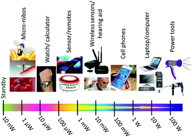
Since the beginning of the industrial revolution the world population has grown multi-fold and this growth is expected to continue at the same pace in the near future.1,2 In the modern world, energy is the most important resource for the growth and sustainability of human life and society. In this context, energy means the capability required to run nano/micro-electronic to macro-electrical systems (Fig. 1).2,3 Limited supplies of fossil fuels and the environmental pollution caused by their use have forced researchers around the world to look for alternative renewable energy resources. Some of the recent efforts in this direction include the development of batteries, fuel cells, and solar cells.In addition to large-scale energy harvesting, small-scale energy scavenging on a level that is sufficient to operate low-power electronic devices, has also attracted the research community. The emerging industrial revolution so called industry 4.0 involves the internet of things (IoT), which will allow all the information related to public safety, human healthcare, environmental changes, and industrial automation to be scrutinized and monitored. This concept assumes the very wide implementation of distributed electronic devices, such as sensors. By continuously harvesting energy, much of which is otherwise wasted, from ambient energy sources such as sunlight, mechanical vibrations, wind, tides/waves, thermal-heat/radiation and magnetic fields, it will be possible to develop an array of self-powered autonomous systems. Energy harvesting will also make it possible to minimize the dependence of wireless sensor networks (WSNs) on external power sources such as batteries.4–8
Powering WSNs with energy harvested from ambient sources can provide several benefits. First, as noted above, it can reduce the dependence on battery power. With the ongoing advancements in nano-/micro-electronics technology, the power consumption of the sensor nodes is becoming smaller and smaller, and in that case the harvested energy may be sufficient to eliminate batteries completely, provided the harvestable energy sources are stable and continuous. Second, the development will reduce installation and maintenance costs. Integrating energy harvesters with the sensor nodes will allow them to function unattended once deployed and eliminates service visits to replace batteries. Next, energy harvesting can make site sensing and actuation capabilities in hard-to-access hazardous locations on a continuous basis possible, provide long-term applications for decades of monitoring, and reduce environmental impacts, such as those associated with the disposal or recycling of batteries.9
In the last decade or so, research groups have been actively developing a range of energy harvesters that can convert tiny mechanical or magnetic energy to usable electricity to power stand-alone electronic systems.5,10–15 This review focuses especially on the methods of harvesting energy from low frequency mechanical vibrations and weak magnetic fields, based on the piezoelectric effect and the magneto-mechano-electric (MME) effect. The fundamentals of piezoelectric-based energy generators and the progress in their development can be found in the literature.16–20 This review article presents a summary of the magnetoelectric phenomena and materials, the design and development of MME generators, and demonstrations of the utilization of the MME generators in some practical applications. Perspectives on the challenges to magnetic energy harvesting, possible ways of improving the energy efficiency of MME generators, and the hybridization of MME generators with harvesters based on other mechanisms are provided.
2. Energy harvesting from ubiquitous magnetic field
In the search for suitable energy sources that are also available in most of the locations where the WSNs of IoT will be used, magnetic fields have been identified as a potential resource, compared with sunlight, mechanical vibrations, heat and other forms of renewable energy. This is because magnetic fields are a direct consequence of current flow. Most of the ambient locations these days possess ubiquitous stray magnetic fields arising from the electric power transmission infrastructure of buildings, overhead power lines, industrial machinery, and consumer electronic devices. These fields are generally considered to be noise and/or harmful to the human body. The electric transmission cables generate low magnetic fields (<1 mT = 10 G at a distance of 10 mm of 50 A current conducting cable) at a fixed frequency of 50/60 Hz.21–23 This magnetic energy can be captured through the use of electromagnetic devices employing coils and magnetic cores and operating on the principle of Faraday's induction law, as well as by the incorporation of recently developed ME composite material based MME generators (Fig. 2).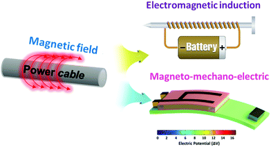 | ||
| Fig. 2 Magnetic energy harvesting techniques: electromagnetic devices using Faraday's induction principle, and multiferroic magnetoelectric composites based on the magneto-mechano-electric process. | ||
2.1 Traditional electromagnetic generators
A current transformer is the commonly used device for magnetic field harvesting and operates on the basis of electromagnetic induction (Faraday's induction).24–26 Tashiro et al., used Brooks coils to harvest electricity from magnetic fields, and a power density of 1.47 μW cm−3 was achieved from a magnetic field of ∼21 μT.21 This output power density was limited due to the core shape and material. A 50 cm long solenoid with a diameter of 5 cm was designed by Roscoe et al., to collect the magnetic field energy in a substation. A power density of 0.85 μW cm−3 was generated when the device was placed in a field of ∼18 μT.27 In that work, cast iron was used as the coil core, which significantly reduces losses from eddy currents. Recently, by optimizing the shape of the coil geometry, and changing the core material and winding method, a bow-tie coil harvester was developed with improved power density (13 μW cm−3) working in the same magnetic field.28Besides the current transformer, another popular system for magnetic field harvesting is the electric field based energy harvester. A 55 cm long tube shaped electric field based energy harvester (weight = 0.7 kg) was reported, which produced a maximum power of 980 mW (corresponding to a power density of 88.6 μW cm−3) on a 63.5 kV power cable.29 This output power was limited due to the loading effect caused by the large impedance of the capacitor.
The literature reported results suggest that the traditional electromagnetic generators have limitations related to size, weight, efficiency, power density, and installation. Besides these limitations, the current transformer type electromagnetic generators are, strictly speaking, outside the concept of energy harvesting. Electromagnetic generators always act as an electrical load to current flowing cables, and thus when electromagnetic generators are deployed in an electrical system, the electric current flows in the system become larger than those in normal operation and affect the quality of the power transmission when the generated power is large. In this regard, such methods can be considered to be ‘stealing electricity from the system’, not harvesting waste energy. For these reasons, researchers have been attempting to create novel approaches to harvest clean energy from magnetic noise fields, with the goal of developing harvesters that not only have smaller size and high efficiency, but also flexibility in where and how they are installed.
2.2 Piezoelectric magnetic energy generator
The multimode harvesting device based on a piezoelectric cantilever and a permanent magnet tip mass, which was first proposed by Xing et al.,30 has demonstrated significantly good magnetic energy harvesting properties at low frequencies.31–34 For excitation these devices use torque-mode magnetic coupling, and the magnetic force experienced by the tip magnets, which originates from the forced alignment of the remanent moment with an external AC magnetic field. This vibrational energy is acquired by the piezoelectric layer and converted into an electric potential through the direct piezoelectric effect. Liu et al., designed a bimorph piezoelectric cantilever structure with PZT and NdFeB magnets, and obtained a maximum power density of 11.73 μW cm−3 for resonance excitations at 100 Hz and 100 μT.32A piezoelectric fiber composite bimorph composed of two piezoelectric PZT-5A fiber layers, which were electrically connected in parallel on a stainless steel layer, was used as the piezoelectric cantilever. A magnet NdFeB N38 (30.5 g) was used as the permanent magnet tip mass and was bonded at the free end of the piezoelectric cantilever. The device was operated in the d33 mode by employing interdigitated electrodes. The piezoelectric fiber showed an improved piezoelectric coefficient d33 of 380 pC N−1 and an electro-mechanical coupling factor k33 of 0.72. The harvester was able to generate a maximum power density of 421 μW cm−3 at 50 Hz and 2 mT.35 However, under low magnetic fields, the harvested output power density from these devices is disappointingly low. An alternative effective technique to harvest magnetic energy is to utilize a multifunctional ME composite. The ME effect is the result of multiple energy transductions, starting from magnetic energy to mechanical energy and finally to electric energy.
3. Multiferroic magnetoelectric MME generators
3.1 Magnetoelectric phenomena
In multiferroic ME materials, polarization is induced by a magnetic field or the magnetization induced by an electric field. ME materials with multifunctionality are in great demand for modern electronics as they enable multitasking, and this in turn widens their application space.36–40 The ME effect arises from the coupling between the magnetic and polar sub-lattices in single phase materials. Due to the improbability of finding magnetic moments and electric dipoles, with long-range order, co-existing in the same phase, very few single phase compounds exhibiting ME effect have been identified. Besides, attempts to achieve sizeable ME coupling in single phase compounds at room temperature have thus far proven unfruitful, because of the difficulties in simultaneously achieving both the transitions: one from ferroelectric to paraelectric states, and another from ferro/ferri/antiferro-magnetic to paramagnetic states.41–43 However, the above limitations can be easily surpassed by combining ferroelectric and ferromagnetic materials in ME composites and taking advantage of the superior properties of these phases. It has been determined and demonstrated that multiphase ME composites are able to exhibit a much better ME response44 than single-phase ME materials45 at room temperature. Layer structured ME composites formed by elastically combining piezoelectric and magnetostrictive materials have been widely studied because of their ease of fabrication and design flexibility.It has been determined that the ME coupling in composites is mediated through strain, or charge carriers, or spin exchange between the constituent phases. Among these mechanisms, the strain-mediated ME coupling is well established, while the other two mechanisms are still being investigated.46,47 The strain-mediated ME coupling in composites results from the elastic coupling between the piezoelectric and magnetostrictive components as illustrated in Fig. 3,44,48 and their detailed operation principles are described below.
 | ||
| Fig. 3 (a) Schematic representation of the direct ME effect in a 2-2 configuration ferroelectric (FE)/ferromagnetic (FM) composite system (the numbers 2-2 refer to the connectivity of the phases in free space);48 (b) illustration of strain-mediated coupling between magnetostriction and piezoelectric effects in an ME composite and its equivalent-circuit expression.44 | ||
In the ME effect, an applied magnetic field generates mechanical deformation/strain in the magnetic layer via the magnetostriction effect, and this strain is transferred to the piezoelectric layer, resulting in an electric displacement or a dielectric polarization through the piezoelectric effect. The ME response is quantified in terms of the ME voltage coefficient αME= δEac/δHac (expressed in V cm−1·Oe−1) (where E is the electric field and H is the magnetic field), which represents the energy conversion ratio between applied Hac and induced Eac under a bias field Hdc.
The strength of the intrinsic ME coupling in the composites depends mainly on the properties of the piezoelectric and magnetostrictive components, the fabrication method, and interfacial coupling and phase connectivity (i.e., the connectivity of the magnetic-piezoelectric phases represented by the numbers 0-3, 1-3, and 2-2, respectively). In recent years, a variety of ME composites have attracted extensive attention, and tremendous progress has been made after the introduction of the 2-2 layered structure by Ryu et al. in 2001.49,50 The results have shown that the 2-2 laminate composites operating in various modes exhibit a higher ME response and are comparatively simpler to fabricate.51 Furthermore, these composites can be electrically or/and magnetically poled to a higher degree since the piezoelectric and magnetic phases are spatially separated, thereby providing higher ME coupling in the layered composite system. Table 1 provides a summary of the progress made in the last decade in the enhancement of ME coefficient αME obtained for different combinations of materials, in off- and on-resonance modes.
| Year | ME Composition | DC Bias field (Oe) | Resonance frequency (Hz) | α ME (V cm−1 Oe−1) | ||
|---|---|---|---|---|---|---|
| Piezoelectric | Magnetostrictive | Off-resonance | Resonance | |||
| 2004 (ref. 58) | PMN–PT | Terfenol-D | 450 | 82.1k | 0.43 | 18.5 |
| 2006 (ref. 59) | PVDF | Metglas | 8 | 50k | 7.2 | 238 |
| 2007 (ref. 60) | PZT–PT | Metglas | 2 | 20k | 10.5 | 400 |
| 2007 (ref. 61) | PZT | Terfenol-D | 1500 | 84k | 0.5 | 18.2 |
| 2011 (ref. 62) | PMN–PT | Metglas | 8 | 27.8k | 45 | 1100 |
| 2012 (ref. 55) | PZT | Metglas | Zero | 60 | — | 274 |
| 2013 (ref. 63) | PZT (MFC) | Nickel | Zero | 507 | 3 | 49.2 |
| 2014 (ref. 64) | PMN–PZT | Nickel | Zero | 23 | 1.4 | 82.9 |
| 2015 (ref. 65) | PMN–PZT | Nickel | Zero | 60 | — | 160 |
| 2016 (ref. 66) | PMN–PZT | Nickel | Zero | 60 | 11.3 | 135.5 |
| 2017 (ref. 67) | KNN | Metglas | 130 | 750 | 9.5 | 1321 |
| 2017 (ref. 44) | PMN–PT | Metglas | 2 | 23k | 29.3 | 7000 |
An important concern when developing an ME energy harvesting device is size miniaturization. Due to the quadratic dependence of magnetostrictive strain (λij) on the applied magnetic field (Hbias), a DC bias magnetic field is usually required, in addition to an AC magnetic field, to enhance the ME coupling of the composites. The need for a DC magnetic source around the ME composites leads to bulky devices which have problems with electromagnetic interference. To overcome these issues, recent efforts have been focused on the development of self-biased magnetoelectric (SME) composites which exhibit an appreciable αME at zero magnetic bias. In these composites, SME coupling can be realized by inducing a built-in magnetic bias in the magnetostrictive layer. Feasible approaches to achieve an SME response include the integration of hard magnetic layers with a permanent moment, the use of remanence magnetization or a field-dependent resonant frequency in a hysteretic magnetostrictive material, and the use of stresses by means of the inverse magnetostriction and exchange biasing of the magnetostrictive material.52,53
3.2 MME generator utilizing ME coupling
All ME composite transducers can be considered potential energy harvesters for scavenging energy from magnetic fields, based on the strong ME coupling between the magnetostrictive and piezoelectric layers. Efforts have also been made to develop magnetic energy harvesters based on various combinations of piezoelectric and magnetostrictive materials.54–56 Ryu et al. demonstrated an MME generator with a simple ME structure that generates electricity from stray magnetic fields.57 The device consisted of asymmetric (PZT ceramic fibers/Ni) or symmetric (Ni/PZT ceramic fibers/Ni) laminate structures and was tested using the stray magnetic vibrations induced by shaking a permanent bar magnet near the device, as shown in Fig. 4. The asymmetric structure exhibited better harvesting performance (peak voltage of 2.5 V) than the symmetric structure (peak voltage of 0.3 V), producing a maximum power of 6 μW at 1 Hz. The sign/magnitude of the harvested voltage depends on the direction of movement of the bar magnet. When the bar magnet moved towards the structure the harvested voltage was negative, and when the magnet moved far away from the structure the harvested voltage was positive, with relatively large magnitudes.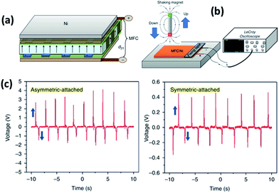 | ||
| Fig. 4 Schematic diagrams showing (a) an asymmetric magnetoelectric laminate structure and (b) magnetic energy harvesting of the induced magnetic signals from the magnetic field noise generated by shaking a magnetic bar. (c) Harvested output voltage signals using asymmetric and symmetric structured devices. The asymmetric structured energy harvester with d31 mode showed superior output performance to those with a symmetric structure.57 | ||
Li et al. developed a magnetic energy harvester using piezoelectric PZT plates, a magnetostrictive Terfenol-D plate and an ultrasonic horn bronze substrate.68 The configuration had a significantly enhanced ME voltage coefficient, related to the commonly used sandwiched laminate composite structure. The energy of the magnetostrictive strain vibration from the magnetostrictive plate is converted using the ultrasonic horn, and additional vibration energy can be converted into electricity through the direct piezoelectric effect, using multiple PZT plates at the resonance frequency of the device. This design can decrease energy losses owing to its high-Q value, and gathers electricity at resonance, producing a maximum output power of 20 μW at 27 kHz. Since the resonance frequency, i.e., driving frequency, of the device is much higher than the general frequency of electric transmission infrastructures, this device cannot be used without a nearby high frequency magnetic field generator. Alternatively, Onuta et al. designed a miniaturized energy harvester using all-thin-film ME structures consisting of PZT and galfenol (Fe0.7Ga0.3) layers.69 The device was fabricated on a micro-machined Si based-cantilever (3.8 μm thick). The Fe0.7Ga0.3 layer (500 nm thick) was sputtered on a Pt-buffered PZT layer (500 nm thick) deposited on a Si based-cantilever. A photo-lithographic process was employed to make an unbent, free-standing cantilever beam structure (950 μm × 200 μm). The device (6.6 mm × 6.6 mm) containing six cantilevers, was mounted in a vacuum chamber placed between a pair of Helmholtz coils, and was aligned parallel to the magnetic fields. The voltage and power outputs showed saturation plateaus with respect to increasing magnetic field. The harvested voltage and peak power were 3.5 mV and 1.05 μW at resonant frequency (3.8 kHz) and 700 μT, respectively.
In 2015, Ryu et al. demonstrated a highly enhanced energy harvesting technique for capturing stray magnetic noise fields, following the MME conversion mechanism.65 The device consisted of one end-clamped cantilever-structured ME composite (anisotropically oriented piezoelectric single crystal fibers and a magnetostrictive Ni plate composite) working in resonance mode with a permanent magnetic proof mass, which interacts (attraction and repulsion) with the surrounding magnetic field to synergistically amplify the bending vibration amplitude. The bending resonance frequency of the device could be adjusted by changing the position and weight of the proof mass.
The fundamental principle of electricity generation in this MME generator is the combined effect of three mechanisms. In the first case, by capturing the parasitic magnetic field noise, the magnetic proof mass will generate a magnetic force moment (FM = 2 × Jr × HAC, Jr is the remanent magnetization polarization density and HAC is the waste magnetic field) applied to the ME composite structure. This results in a bending vibration of the MME generator. Then the piezoelectric layer converts the acquired vibrational energy into the piezoelectric potential by breaking the central symmetry in the crystal structure (i.e., the direct piezoelectric effect). The second mechanism is based on ME coupling, which is related to the magnetostrictive behavior (strain is proportional to the square of the applied magnetic field) which induces interfacial coupling between the piezoelectric layer and magnetostrictive layer, thereby creating a piezoelectric potential through the direct piezoelectric effect. In the third case, an additional magnetic force is generated by the magnetostrictive layer due to the magnetostrictive strain vibrations, which further excite the vibrational deflection amplitudes of the generator. All three of these individual energy conversion mechanisms are simultaneously cross-linked for energy harvesting.32,65,70 The sequential harvesting mechanism is schematically presented in Fig. 5. For these mechanisms, the strain transfer between the two layers plays a vital role in energy harvesting performance.
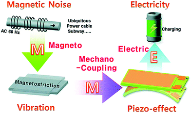 | ||
| Fig. 5 Operating principle and schematic diagram of the energy-transfer processes in a magnetic energy harvesting device with multiferroic magnetoelectric composites.65 | ||
3.3 Anisotropic piezoelectric single-crystal macro-fiber composites for MME generators
The piezoelectric material used for the MME generators in the cantilever structures should have high transverse piezoelectric coefficients in order to harvest energy with high power density. Single crystal piezoelectric materials, due to their uniform dipole alignment, exhibit better piezoelectric performance than their polycrystalline counterparts. Furthermore, the crystallographic anisotropy of these single crystals can be exploited to achieve higher piezoelectric performance. Rhombohedral structured, domain engineered, relaxor-based ferroelectric single crystals (e.g. PMN–PT, PZN–PT, and PMN–PZT) display greatly enhanced piezoelectric coefficients and electromechanical coupling factors along the [001] and [011] non-polar orientations, as compared to the [111] spontaneous polarization direction. There are eight possible spontaneous polarization directions, prior to poling, in a rhombohedral single crystal. When poled along the [111] direction, only one spontaneous polarization orientation remains to form a single domain state. In contrast, the single crystals poled along [001] or [011] display a multidomain configuration. Moreover, these single crystals show isotropy ((001) oriented) or anisotropy ((011) oriented) in their transverse piezoelectric properties, which can be attributed to the differences in the domain states produced upon their poling.71–75 The enhanced piezoelectric response of the relaxor-based ferroelectric single crystals is related to the effect of morphotropic phase boundary (MPB) composition, polarization rotation, and crystallographic orientation.76 The results have shown that designing ME composites with specially oriented single crystals is an efficient approach to optimize the ME coupling.75,77–81Based on the above design concept, Ryu et al. designed high performance MME generators that effectively invoke the k32 mode.65 Piezoelectric PMN–PZT single crystals with a rhombohedral structure have different types of crystallographic orientations. Because of their intrinsic rigidity and brittleness, single crystal sheets have not been practical for application in MME generators for low frequency flexural operation. To enhance their structural flexibility and reliability, high-performance flexible single-crystal macro-fiber composites (SFCs; 28 (L) × 0.35 (W) × 0.2 (T) mm3) were designed and used for MME generators as shown in Fig. 6. The device consists of an anisotropic piezoelectric SFC and a magnetostrictive Ni plate in the form of a one end clamped cantilever structure. The harvesting performance of the MME generator was tested, without applying an external magnetic DC field, using a Helmholtz coil, which can generate a magnetic noise field similar to that of a fixed frequency of 60 Hz found in an ambient environment. The generated peak-to-peak voltages under open circuit conditions were 6.5, 3.5, and 9.5 V respectively, for 〈001〉-d31, 〈011〉-d31, and 〈011〉-d32 SFC embedded MME generators when they were operated under the condition of HAC = 160 μT at a bending anti-resonance frequency of 60 Hz. These results demonstrated that the anisotropic 〈011〉 SFC in the k32 mode had a much large energy generation performance compared to other modes. In particular, the value of d32 = −1850 pC N−1 for the anisotropic 〈011〉 SFC represents a three-fold improvement over similar values for 〈011〉-d31 SFC (599 pC N−1). The harvesting performance of the piezoelectric-based energy harvester at off-resonance is directly related to the product of the piezoelectric strain coefficient, and the piezoelectric voltage coefficient (figure of merit, FOM = dij × gij). The FOM factors for 〈001〉-d31, 〈011〉-d31, and 〈011〉-d32 SFC were 38.4, 9.1, and 309.2 pm2 N−1, respectively.
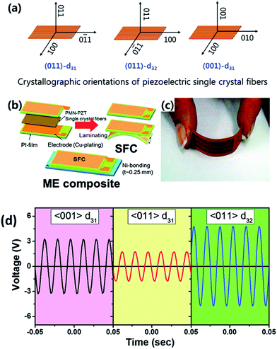 | ||
| Fig. 6 Schematic illustrations showing the crystallographic orientations of piezoelectric single crystal fibers, which are used in ME composites (a) and fabrication procedure for the ME composite (b). (c) A photograph of a flexible SFC for the device. (d) The harvested output voltages from the MME generators working in different modes. Here the device was operated at the 1st bending mode anti-resonance frequency (60 Hz) and a magnetic noise field of 160 μT.65 | ||
Furthermore, when the 〈011〉-d32 SFC embedded MME generator was tested with HAC ∼ 500 μT field, it was able to turn on/off 35 high-intensity LEDs at a frequency of ∼1 Hz (Fig. 7), clearly demonstrating its feasibility as a power source for WSNs, portable electronics, and wireless charging systems. A wireless sensor network module composed of a power management circuit, rechargeable capacitors, a microcontroller, and a wireless transceiver was successfully driven by the generator working under a magnetic noise field of ∼700 μT at 60 Hz (Fig. 7).
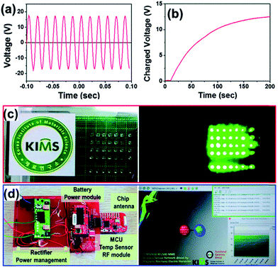 | ||
| Fig. 7 (a) Measured output voltage signal harvested from the MME generator embedded with the anisotropic 〈011〉 SFC in d32 mode under a magnetic noise level of 500 μT. The maximum generated peak-to-peak voltage is 34 V. (b) The charge curve of a capacitor (capacity 220 μF) using the MME generator rectified by using a full-wave-bridge rectifier. (c) A photograph of 35 LEDs lit up using the power harvested by the generator. (d) Self-powered autonomous electronic device with a power management circuit, rechargeable batteries, an RF communication circuit, temperature sensor mode and a MME generator and captured WSNs software driven by the generator.65 | ||
3.4 Loss factor of piezoelectric materials for MME generators
The hysteresis of the piezoelectric materials is related to losses, including dielectric loss, i.e., the inverse of the electrical quality factor, and mechanical loss, i.e., the inverse of the mechanical quality factor, which degrade the performance of the device.82 To avoid this problem, efforts have also been focused on synthesizing low-loss single crystals for use in energy harvesters.50,66,83 Three energy generators using ME composites embedded with high-loss, medium-loss, and low-loss PMN–PZT SFCs as the piezoelectric material were designed and tested, as shown in Fig. 8.66 By changing the dopant (MnO or WO3) and concentration of the dopant, the piezoelectric properties of the PMN–PZT single crystals were modulated. After optimization of the above variants in the PMN–PZT single crystals, the composition 40PMN–35PZ–25PT + 1 mol% WO3 and 40PMN–35PZ–25PT + 1 mol% MnO exhibited modulated piezoelectric properties (Qm, loss, dij, gij,etc.) with medium-loss and low-loss factors, as compared to un-doped PMN–PZT single crystals with high-loss factors.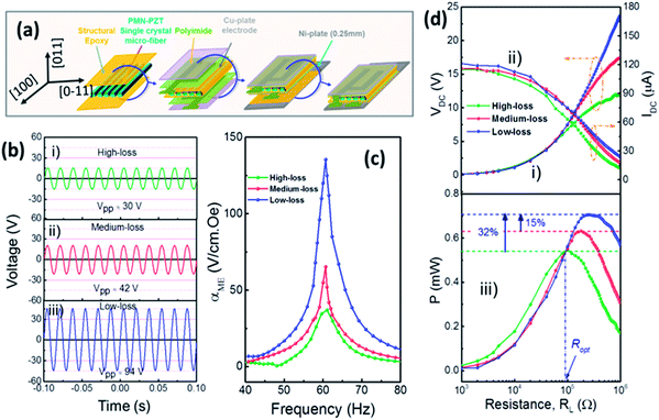 | ||
| Fig. 8 (a) Structure and fabrication process of the MME generator. (b) Harvested open-circuit output voltage signals (magnetic noise field = 700 μT) and (c) measured resonance spectra of the induced magnetoelectric coupling coefficient from various MME generators. A clear resonance peak was obtained at 60 Hz and better performance was obtained from the low-loss embedded MME generator. Even though there was no bias field, a maximum ME coefficient of 135.5 V cm−1 Oe−1 was obtained from the low-loss MME generator. (d) The rectified DC current and DC voltage measured at various external load values. The open-circuit voltage and short-circuit current values were 24 V and 120 μA (corresponding to a current density of 35 μA cm−2). The power output was calculated by multiplying the current and voltage outputs obtained at a specific external resistance.66 | ||
For the MME generator to be effectively utilized as an energy source for various low-power-consumption electronics, it should be able to extract the maximum possible electricity from the stray magnetic field. Fig. 8 shows the output voltage and current from generators using various integrated piezoelectric SFCs, described above. The MME generator using the low-loss SFC exhibited a maximum output of 94 V (peak-to-peak voltage) and ∼120 μA (short-circuit current), while the high-loss SFC based MME generator showed an open-circuit voltage of 30 V with a short-circuit current output of ∼115 μA, when subjected to a maximum magnetic noise field of 700 μT at 60 Hz. Because the ME response of the device is directly related to the harvesting voltage, the low-loss PMN–PZT integrated MME generator had a much higher harvesting output performance compared to the other two generators.
The individually harvested AC signals of the generators must be converted into DC signals and subsequently accumulated in a rechargeable battery or a capacitor to provide a constant power source to the external electronics using a power management circuit. The characterized output measured at various external load resistance values is presented in Fig. 8. The generated maximum power was about 0.73 mW (corresponding to an output power density of 2.1 mW cm−3). Furthermore, maintaining the performance of the device under a continuous magnetic field is an important issue for practical applications. The low-loss MME generator continuously generated highly stable output voltage over as many as 108 fatigue cycles.
A self-powered electronic system for charging a mobile phone battery was constructed based on an MME generator integrated with a rectifier circuit, a supercapacitor used as a storage capacitor, and a commercially available DC–DC power-management circuit (see Fig. 9). The generated electric power was used to charge a supercapacitor (over 1 F capacity = 2.5 J) to operate the electronic devices. The stored electricity was utilized to charge a mobile phone battery and also to drive a small DC-motor fan.
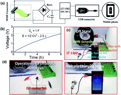 | ||
| Fig. 9 (a) A schematic circuit diagram of the self-powered electronic circuit system for charging a mobile phone battery. (b) Charge curve of a super-capacitor (capacity 1 F) for energy storage by the low-loss MME generator. (c) and (d) Snapshot images of a mobile phone battery in battery charging mode and a small DC-motor fan.66 | ||
3.5 Tailored cantilever geometries for MME generators
The shape of the cantilever structure impacts several parameters, including the strain distribution for a given magnetic field, the elastic compliance of the material, and resonance frequency of the device.84,85 A broader consideration of potential design geometries can significantly increase the harvester performance. It is important to tailor the device structure of the MME generator to achieve high-output performance.Various shapes of ME composites have been designed using piezoelectric PMN–PZT single crystal macro-filers and a magnetostrictive Ni layer (Fig. 10).70 The strain distribution in each structure was estimated using finite element analysis (FEA), with ATILA++ software, which allows the identification of the shape with optimum strain distribution in the device. The in-plane strain value at the free-end of the piezoelectric region was 26% higher than that at its clamped-end for a rectangular shaped structure (b/a = 1), and was increased to 62% for a taper-shaped structure (b/a = 0.22). The harvested voltage waveforms of the MME generators at a resonance frequency of 40 Hz with a magnetic noise field of 200 μT are presented in Fig. 10. The MME generators with b/a ratios of 1, 0.68, 0.45, and 0.22 generated open-circuit peak-to-peak voltages of 11.6, 13.0, 16.0, and 24.5, respectively.
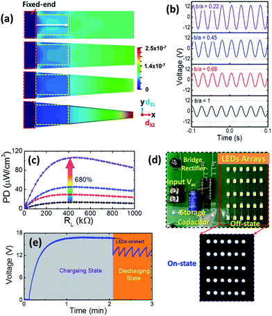 | ||
| Fig. 10 (a) The in-plane interfacial strain distribution using finite element analysis (FEA) software (ATILA++). The rectangular yellow color represents an active piezoelectric layer region. (b) The harvested output voltage signals and (c) output power density measured after a full wave rectifier bridge under a magnetic field of 200 μT at a resonance frequency of 40 Hz. (d) Image of commercial LEDs, which are incorporated into the circuit, and an image of the LEDs in a dim background at the moment when they were lit up by the energy generated from the MME generator. (e) Charge and discharge curve of the storage capacitor (20 μF) for storing electricity produced by the generator, and the subsequent operation of LEDs.70 | ||
The harvester waveforms were converted into direct-current signals using a full bridge rectifier, a smoothing capacitor, and a variable load resistor. For electric impedance matching, the internal impedance of the generator should be similar to the load resistance of the storage capacitor network. A maximum output power was generated using the tapered shape structured MME generator, of about 108 μW cm−3. By tailoring the geometry of the generator, the maximum power was improved by 680%, compared to the regular rectangular structured MME generator. To demonstrate the capacity of the newly designed structure of MME generators as a direct power source, a total of 30 commercial LEDs were utilized as an operating load (Fig. 10). The emitted light lasted 1–2 s and was clearly captured on a dim background. Therefore, with a tailored device structure, not only can the MME generator benefit from substantial enhancements in voltage and power, but also can enable the full bridge rectifier to continuously operate electronic devices without using any other external battery sources.
3.6 Dual phase (mechanical and magnetic) energy harvesting
In many industrial environments, mechanical vibrations generally occur in tandem with electromagnetic fields. Since MME generators utilize both the piezoelectric and ME effects, they are capable of simultaneously harvesting energy from both mechanical vibrations and alternating magnetic fields. Such a combination is considered to be a good strategy for enhancing the efficiency and power output of ME energy harvesters86 as well as broadening of the applicable arena of MME generators. A dual-phase (vibration and magnetic) or hybrid MME generator system combines the ME coupling and piezoelectric energy harvesting mechanisms, as shown in Fig. 11. To characterize the dual-phase mode of the harvester, the MME generator is simultaneously excited by an AC magnetic field (Hac) generated by a Helmholtz coil and a mechanical oscillation generated by a shaker.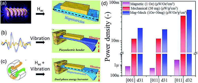 | ||
| Fig. 11 Schematic diagrams depicting ME energy harvesters using (a) AC magnetic field, (b) mechanical vibration, and (c) dual-phase excitation. (d) Comparison of the power densities of the Ni/SFC cantilever ME energy harvesters, for single excitations and dual phase excitations.63,64,86 | ||
Dong et al. fabricated a hybrid harvesting device consisting of a cantilever beam with a tip mass and a magnetoelectric laminate of FeBSiC alloy ribbons and PZT fibers attached to the center of the beam.54 The device was shown to generate an open circuit voltage of 8 Vp-p under a mechanical vibration amplitude of 50 mg and an AC magnetic field of 2 Oe. Using the dual energy source, the output voltages were found to be doubled as compared to those of a single source. Kambale et al. designed ME unimorph bender type cantilevers by incorporating 〈001〉− and 〈011〉-oriented PMN–PZT single crystals into a Ni plate.87 Under an excitation of 0.7 Oe and a 3 g proof mass, the hybrid system with 〈011〉-oriented PMN–PZT in the k32 mode demonstrated a power output of 17.06 mW cm−3, better than other orientations of PMN–PZT. Zhou et al. reported a self-biased dual-phase ME energy harvester structure consisting of a PZT ceramic based macro-fiber composite bonded to a Ni cantilever.63 At zero magnetic bias, an additive effect was realized when the harvester was operated in dual-phase mode (with 1 Oe magnetic field and 1 g acceleration) resulting in a power density of 4.5 mW cm−3, which is better than that obtained in the vibration or magnetic field mode alone.
Recently, Patil et al. reported an anisotropic self-biased dual-phase ME energy harvester using magnetostrictive nickel (Ni) metal shims laminated with single crystal fiber composites (SFCs) with anisotropic transverse piezoelectric properties.64 A hybrid system with a Ni/〈011〉-d32 SFC cantilever showed better performance, with an open circuit output voltage of 20 Vp-p and a power density of 59.78 mW Oe−2 g−2 cm−3 (with 1 Oe field and 30 mg acceleration). For all three ME energy harvesters, prepared with a Ni/〈011〉-d32 SFC cantilever, a Ni/〈011〉-d31 SFC cantilever, and a Ni/〈001〉 d31-SFC cantilever, the power densities were enhanced under dual phase excitation (Fig. 11). The above results demonstrate that the combination of AC magnetic field and mechanical vibration can greatly enhance the power densities of the MME generators even under zero-bias conditions. These are significant advances towards developing high performance hybrid MME generator systems.
3.7 Efficiency of the MME generator
The conversion efficiency (η) of a MME generator is determined by the fraction of energy gathered by the magnetic layer, which is converted to electricity, and is expressed as: | (1) |
The input power (Pin) is related to the incident magnetic noise energy spread through the volume of the device. The magnetic energy collected by the MME generator is33,68,88
 | (2) |
To summarize the progress that has been made, in the last few years, in the performance of the MME generator, a three order of magnitude enhancement in output power as well as a significant improvement in conversion efficiency has been achieved. The volume power density reached 6.6 mW cm−3 and greater than 30% conversion efficiency was obtained. We anticipate that further enhancements in the output power density will be demonstrated in the near future.
4. Comparison between MME generators and other energy harvesting technologies
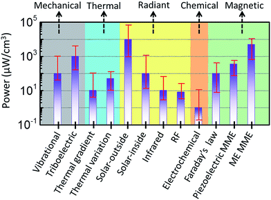
To make the sensor node truly autonomous and self-sustainable in the WSN, the energy consumption of the WSN must be entirely scavenged from the environment. In this regard, the choice of the energy harvesting technique is crucial. Fig. 12 presents a compilation of the power densities derived from various energy harvesting techniques. Although, the solar cells installed outdoor yield the highest power density, measuring above 100 mW cm−3, under indoor conditions, the energy harvested by the solar panels drops tremendously, to about 0.1 mW cm−3. Other energy harvesting techniques can be competitive based on the requirements of the devices. A suitable energy harvesting source should be selected to power the load for a specific application based on the harvestable energy sources available in the specific application areas. Since stray magnetic fields are ubiquitous and can be readily accessed, they provide an important avenue toward building self-powered autonomous electronic systems. Another best possible solution is when two or more energy sources are available for harvesting, where the so-called hybridization of energy harvesters also present an interesting option for an energy-hunger load.5. Perspectives on potential advances in MME generators
5.1 Textured magnetostrictive materials for MME generators
As aforementioned, an MME generator mainly uses the coupling effect between piezoelectric and magnetostrictive constituents. Although textured/single crystal piezoelectric materials have been widely employed in the ME composites, magnetostrictive materials used so far for the same have been mostly polycrystalline. It is expected that by using textured/single crystal forms of both piezoelectric and magnetostrictive materials the power output of MME generators can be further improved. Recently, some new grades of alfenol (Fe–Al) and galfenol (Fe–Ga) alloys with strong texture have been developed. These alloys showed not only good magnetostriction characteristics, but also strong anisotropic behaviors.89 Also, these magnetostrictive materials could exhibit good ductility and magneto-mechanical coupling, which are beneficial for magnetic-mechanical energy transfer in low magnetic field environments.5.2 Hybridization of MME generators with other types of energy harvesters
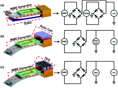
The hybridization of multiple energy harvesters to simultaneously harvest electricity from various types of energy sources would significantly improve their output performance. The MME generator can possibly be combined with several other harvesting devices, such as triboelectric nanogenerators (TENGs), piezoelectric nanogenerators (PNG), solar cells, and thermoelectric generators (TEGs). These hybrid energy harvesters could be developed to individually or simultaneously harvest electric power from diverse energy sources, including magnetic fields, sun-light and temperature gradients. To integrate two or more energy generators requires the design of appropriate electric circuits, since MME and triboelectric harvesters generate AC electric energy, whereas solar cells and thermoelectric generators generate DC electric energy. The AC-type harvesters require a highly efficient rectifying circuit to convert the AC output into a DC output to operate conventional electronic devices. Fig. 13 shows schematic illustrations for the proposed device structures and equivalent circuit designs for hybrid energy harvesters.Like the MME, the TENG is also operated by mechanical vibration; which makes it reasonable to structurally combine the TENG with MME generator devices. The triboelectric effect is a contact electrification process, in which a certain material becomes electrically charged by mechanical contact with a different material.90 The sign of the charges for the contacted materials is determined by the relative polarity of a material compared to the other material. Normally, a strong triboelectric effect is produced by insulators or less conductive materials, and they can capture the transferred charges and keep them for a prolonged time. Recent TENG devices provide a new approach to generate electric energy from mechanical energy to operate small consumer electronics. They offer several benefits, with many material options, outstanding output, cost-effectiveness, and facile mass production.91 Since the MME generators harvest mechanical vibration under an ambient magnetic field, the active materials and electrodes for TENG can be attached to the piezoelectric component to convert mechanical energy into electricity and further enhance the total power output of MME generators.
One of the promising applications of the MME generator is the structural health monitoring (SHM) of outdoor power cables, which offers a continuous magnetic field for the MME generator. In an open-air environment electric output could be obtained from solar energy by utilizing solar cell devices as well. Sunlight is considered the most important and sustainable renewable energy source because of its properties of universal presence, cleanness, and infinite quantity.92–94 In solar cells, the photovoltaic effect can convert the light source directly into electricity, through a sequence of light absorption on a semiconductor layer, excitation of electrons, electron–hole separation, and charge transport to electrodes. Because, the solar cell generates a DC current, unlike the AC current output of the MME, the current from the solar harvesting device needs rectification to be hybridized electrically with a MME generator. The solar cells generate a relatively high DC output current (e.g., tens of mA) which could complement the relatively low output current (e.g., a few hundred μA) of the MME generator. Furthermore, the relatively high voltage output (e.g., scores of V) of the MME generator could synergistically increase the output voltage of the solar cell in the hybrid energy harvester.
In some situations, a magnetic field and thermal gradient coexist, as occurs in an operating computer, the engine compartment of a car, and an electrical distribution board. Under these conditions, both an MME generator and a TEG can simultaneously generate electricity by hybridization. The TEG device is based on the Seebeck effect, which exploits the difference in temperature between two ends of the TEG to drive charge carrier diffusion, and consequently the TEG can convert a temperature gradient into electric energy.95 Moreover, the TEG has the advantages of being compact, simple, reliable, and robust, since it does not include any mechanical moving parts. Like the solar cell, the TEG device generates a relatively large output current (e.g., a few hundred mA) and low output voltage (e.g., a few hundred mV) in DC form.96 Therefore, the MME generator could be relatively easily connected with the TEG to reinforce their electric output for appropriate applications.
5.3 Magnetic field concentration for active harvesting
The MME generator based on ME coupling uses mechanical vibration induced by the alternation of a magnetic field. Theoretically, the amplitude of the mechanical vibration of the MME generator is proportional to the intensity of the magnetic field surrounding the generator, and thus the magnetic field distribution inside the generator impacts the deformation and the resultant power output of the device. In most published reports, the magnetic field inside the ME composites or MME generators is assumed to be identical to the applied magnetic field, or is only disturbed by the geometry of the magnetostrictive material,97 but this is not realistic.In a magnetic material with very high permeability such as Metglas, however, the magnetic field inside the material is more concentrated than in the ambient magnetic field, which is not what many researchers assume. This effect is known as magnetic flux concentration, and some research groups have tried to adapt this phenomenon to develop high sensitivity magnetic field sensors using ME composites.98Fig. 14 shows the finite element simulation result for a high permeability Metglas sheet as reported by Fang et al.99 The results clearly demonstrate that the magnetic flux density inside the Metglas is much higher than that in free space. This magnetic flux concentration effect not only remarkably enhanced the ME coupling coefficient, but also the magnetic field sensitivity of the ME based sensors. The magnetic flux concentration effect of a high permeability magnetic material can be directly applied to further enhance the performance of the MME generator. It might be possible to amplify a tiny ambient magnetic noise into a high magnetic flux inside the MME generator, which can enlarge the resulting vibration amplitude, by locating high permeability magnetic materials near the MME generator, so that the magnetic field can be focused inside the MME generator. Using this magnetic flux concentration effect provided by the high permeability magnetic material, the harvesting energy density of MME generators could be drastically enhanced.
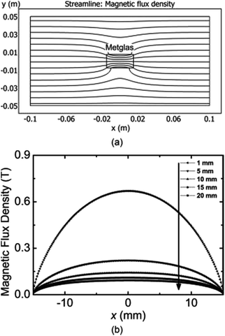 | ||
| Fig. 14 Magnetic flux density distribution of high permeability magnetic material in free space along the x-axis.99 | ||
6. Summary
A great deal of effort has been invested in the development of promising energy harvesters in recent years. Among the various energy harvesting technologies, the MME generator has high potential as a ubiquitous and autonomous power supplier, since it can harvest energy from tiny levels of magnetic noise, in an ambient environment and turn it into usable electricity. Although it cannot generate enough power to operate electronics requiring high power, it might be able to generate sufficient energy to operate low power consuming electronic devices, such as WSNs of IoT, wearable devices, and mobile applications in the near future. Though some prototype MME generators based on bulk ME composites have already been demonstrated, some challenges still exist in terms of obtaining more harvesting power density and compactness, which can be addressed by tailoring the variables for optimal material selection, vibration mode control, magnetic flux concentration, and hybridization. Furthermore, the reliability (fatigue and environmental durability) of the MME generators in practical applications should also be investigated. It is believed that there are still many avenues to explore, in pursuit of practical implementation of MME generators.Conflicts of interest
There are no conflicts to declare.Acknowledgements
This research work was mainly supported by the Global Frontier R&D Program on Center for Hybrid Interface Materials (HIM) funded by the Ministry of Science, ICT & Future Planning Korea (Grant No. NRF-2016M3A6B1925390); Korea Institute of Materials Science (KIMS) internal R&D program (Grant No. PNK5061); and the U.S. Office of Naval Research Global (Grant No. N62909-16-1-2135). DYJ acknowledges the support under the framework of the 2017 international cooperation program managed by the National Research Foundation of Korea (Grant No.: 2017K1A4A3013662) and WCSL program in Inha University.Notes and references
- R. Lee, Science, 2011, 333, 569 CrossRef CAS PubMed
.
- S. Chu and A. Majumdar, Nature, 2012, 488, 294 CrossRef CAS PubMed
.
-
Y. Kheng and S. Kumar, in Sustain. Wirel. Sens. Networks, InTech, 2010 Search PubMed
.
- D. Makarov, M. Melzer, D. Karnaushenko and O. G. Schmidt, Appl. Phys. Rev., 2016, 3, 11101 Search PubMed
.
- Z. L. Wang, ACS Nano, 2013, 7, 9533 CrossRef CAS PubMed
.
- L. Peng, L. Hu and X. Fang, Adv. Funct. Mater., 2014, 24, 2591 CrossRef CAS
.
- V. Bhatnagar and P. Owende, Energy Sci. Eng., 2015, 3, 153 CrossRef
.
- A. Nechibvute, A. Chawanda and P. Luhanga, Smart Mater. Res., 2012, 2012, 1 CrossRef
.
- S. Thakur, D. Prasad and A. Verma, Int. J. Comput. Appl., 2017, 165, 19 Search PubMed
.
- C. K. Jeong, J. Lee, S. Han, J. Ryu, G.-T. Hwang, D. Y. Park, J. H. Park, S. S. Lee, M. Byun, S. H. Ko and K. J. Lee, Adv. Mater., 2015, 27, 2866 CrossRef CAS PubMed
.
- K. Il Park, J. H. Son, G. T. Hwang, C. K. Jeong, J. Ryu, M. Koo, I. Choi, S. H. Lee, M. Byun, Z. L. Wang and K. J. Lee, Adv. Mater., 2014, 26, 2514 CrossRef PubMed
.
- G.-T. Hwang, V. Annapureddy, J. H. Han, D. J. Joe, C. Baek, D. Y. Park, D. H. Kim, J. H. Park, C. K. Jeong, K.-I. Park, J.-J. Choi, D. K. Kim, J. Ryu and K. J. Lee, Adv. Energy Mater., 2016, 6, 1600237 CrossRef
.
- V. Annapureddy, H. Palneedi, W. Yoon, D. Park, J. Choi, B. Hahn, C. Ahn, J. Kim, D. Jeong and J. Ryu, Sens. Actuators, A, 2017, 260, 206 CrossRef CAS
.
- E. L. Tsege, G. H. Kim, V. Annapureddy, B. Kim, H.-K. Kim and Y.-H. Hwang, RSC Adv., 2016, 6, 81426 RSC
.
- B. Xu, H. Chakraborty, R. C. Remsing, M. L. Klein and S. Ren, Adv. Mater., 2017, 29, 1605150 CrossRef PubMed
.
- S. Priya, H.-C. Song, Y. Zhou, R. Varghese, A. Chopra, S.-G. Kim, I. Kanno, L. Wu, D. S. Ha, J. Ryu and R. G. Polcawich, Energy Harvesting and Systems, 2017, 4, 3 CrossRef
.
- A. Toprak and O. Tigli, Appl. Phys. Rev., 2014, 1, 31104 Search PubMed
.
- D. J. Joe, S. Kim, J. H. Park, D. Y. Park, H. E. Lee, T. H. Im, I. Choi, R. S. Ruoff and K. J. Lee, Adv. Mater., 2017, 1606586 CrossRef PubMed
.
- C. K. Jeong, J. Y. Han, H. Palneedi, H. Park, G.-T. Hwang, B. Joung, S.-G. Kim, H. J. Shin, I.-S. Kang, J. Ryu and K. J. Lee, APL Mater., 2017, 5, 074102 CrossRef
.
- C. K. Jeong, S. B. Cho, J. H. Han, D. Y. Park, S. Yang, K.-I. Park, J. Ryu, H. Sohn, Y.-C. Chung and K. J. Lee, Nano Res., 2017, 10, 437 CrossRef CAS
.
- K. Tashiro, H. Wakiwaka, S. I. Inoue and Y. Uchiyama, IEEE Trans. Magn., 2011, 47, 4441 CrossRef
.
- K. J. P. Vecchia, M. Hietanen, R. Matthes, A. Ahlbom, E. Breitbart, F. R. de Gruijl, M. Feychting and A. Green, Health Phys., 2010, 99, 818 Search PubMed
.
- M. N. Halgamuge, C. D. Abeyrathne and P. Mendis, Radiat. Prot. Dosim., 2010, 141, 255 CrossRef PubMed
.
- M. J. Moser, T. Bretterklieber, H. Zangl and G. Brasseur, IEEE Trans. Ind. Electron., 2011, 58, 2597 CrossRef
.
-
V. Gupta, A. Kandhalu and R. Rajkumar, in Proc. 6th Work. Hot Top. Embed. Networked Sensors - HotEmNets ’10, ACM Press, New York, USA, 2010 Search PubMed
.
-
K. Tashiro, A. Ikegami, S. Shimada, H. Kojima and H. Wakiwaka, in Int. Conf. Sens. Technol., 2016 Search PubMed
.
- N. M. Roscoe and M. D. Judd, IEEE Sens. J., 2013, 13, 2263 CrossRef
.
- S. Yuan, Y. Huang, J. Zhou, Q. Xu, C. Song and P. Thompson, IEEE Trans Power Electron, 2015, 30, 6191 CrossRef
.
-
F. Guo, H. Hayat and J. Wang, in 2011 IEEE Power Energy Soc. Gen. Meet., IEEE, 2011 Search PubMed
.
- Z. Xing, J. Li and D. Viehland, Appl. Phys. Lett., 2008, 93, 13505 CrossRef
.
- Y. Shi, H. Yao and Y. Gao, J. Alloys Compd., 2017, 693, 989 CrossRef CAS
.
- G. Liu, P. Ci and S. Dong, Appl. Phys. Lett., 2014, 104, 32908 CrossRef
.
- W. He, P. Li, Y. Wen, J. Zhang, A. Yang, C. Lu, J. Yang, J. Wen, J. Qiu, Y. Zhu and M. Yu, Sens. Actuators, A, 2013, 193, 59 CrossRef CAS
.
- W. He, P. Li, Y. Wen, J. Zhang, C. Lu and A. Yang, Rev. Sci. Instrum., 2013, 84, 105004 CrossRef PubMed
.
- J. Han, J. Hu, Z. Wang, S. X. Wang and J. He, J. Appl. Phys., 2015, 117, 144502 CrossRef
.
- J. Ma, J. Hu, Z. Li and C.-W. Nan, Adv. Mater., 2011, 23, 1062 CrossRef CAS PubMed
.
- N. a. Hill, J. Phys. Chem. B, 2000, 104, 6694 CrossRef CAS
.
- H. Palneedi, V. Annapureddy, S. Priya and J. Ryu, Actuators, 2016, 5, 9 CrossRef
.
- J. F. Scott, J. Mater. Chem., 2012, 22, 4567 RSC
.
- M. M. Vopson, Crit. Rev. Solid State Mater. Sci., 2015, 40, 223 CrossRef CAS
.
- S.-W. Cheong and M. Mostovoy, Nat. Mater., 2007, 6, 13 CrossRef CAS PubMed
.
- V. Annapu Reddy, N. P. Pathak and R. Nath, J. Alloys Compd., 2012, 543, 206 CrossRef CAS
.
- S. Priya, R. Islam, S. Dong and D. Viehland, J. Electroceram., 2007, 19, 147 CAS
.
- Z. Chu, H. Shi, W. Shi, G. Liu, J. Wu, J. Yang and S. Dong, Adv. Mater., 2017, 29, 1606022 CrossRef PubMed
.
- V. Annapu Reddy, N. P. Pathak and R. Nath, Thin Solid Films, 2013, 527, 358 CrossRef CAS
.
- C. A. F. Vaz, J. Hoffman, C. H. Ahn and R. Ramesh, Adv. Mater., 2010, 22, 2900 CrossRef CAS PubMed
.
- C. A. Fernandes Vaz and U. Staub, J. Mater. Chem. C, 2013, 1, 6731 RSC
.
- H. Palneedi, D. Maurya, G.-Y. Kim, V. Annapureddy, M.-S. Noh, C.-Y. Kang, J.-W. Kim, J.-J. Choi, S.-Y. Choi, S.-Y. Chung, S.-J. L. Kang, S. Priya and J. Ryu, Adv. Mater., 2017, 29, 1605688 CrossRef PubMed
.
- J. Ryu, A. V. Carazo, K. Uchino and H.-E. Kim, Jpn. J. Appl. Phys., 2001, 40, 4948 CrossRef CAS
.
- J. Ryu, S. Priya, K. Uchino and H.-E. Kim, J. Electroceram., 2002, 8, 107 CrossRef CAS
.
- J. Ma, J. Hu, Z. Li and C.-W. Nan, Adv. Mater., 2011, 23, 1062 CrossRef CAS PubMed
.
- E. Lage, C. Kirchhof, V. Hrkac, L. Kienle, R. Jahns, R. Knöchel, E. Quandt and D. Meyners, Nat. Mater., 2012, 11, 523 CrossRef CAS PubMed
.
- Y. Zhou, D. Maurya, Y. Yan, G. Srinivasan, E. Quandt and S. Priya, Energy Harvesting and Systems, 2015, 3, 1 CrossRef
.
- S. Dong, J. Zhai, J. F. Li, D. Viehland and S. Priya, Appl. Phys. Lett., 2008, 93, 103511 CrossRef
.
- J. Gao, D. Hasanyan, Y. Shen, Y. Wang, J. Li and D. Viehland, J. Appl. Phys., 2012, 112, 104101 CrossRef
.
- A. Lasheras, J. Gutiérrez, S. Reis, D. Sousa, M. Silva, P. Martins, S. Lanceros-Mendez, J. M. Barandiarán, D. A. Shishkin and A. P. Potapov, Smart Mater. Struct., 2015, 24, 65024 CrossRef
.
- R. C. Kambale, J.-E. Kang, W.-H. Yoon, D.-S. Park, J.-J. Choi, C.-W. Ahn, J.-W. Kim, B.-D. Hahn, D.-Y. Jeong, Y.-D. Kim, S. Dong and J. Ryu, Energy Harvesting and Systems, 2014, 1, 3 CrossRef
.
- S. Dong, J.-F. Li and D. Viehland, Appl. Phys. Lett., 2004, 85, 5305 CrossRef CAS
.
- J. Zhai, S. Dong, Z. Xing, J. Li and D. Viehland, Appl. Phys. Lett., 2006, 89, 83507 CrossRef
.
- S. Dong, J. Zhai, Z. Xing, J. Li and D. Viehland, Appl. Phys. Lett., 2007, 91, 22915 CrossRef
.
- J. Ma, Z. Shi and C. W. Nan, Adv. Mater., 2007, 19, 2571 CrossRef CAS
.
- J. Gao, L. Shen, Y. Wang, D. Gray, J. Li and D. Viehland, J. Appl. Phys., 2011, 109, 74507 CrossRef
.
- Y. Zhou, D. J. Apo and S. Priya, Appl. Phys. Lett., 2013, 103, 192909 CrossRef
.
- D. R. Patil, Y. Zhou, J.-E. Kang, N. Sharpes, D.-Y. Jeong, Y.-D. Kim, K. H. Kim, S. Priya and J. Ryu, APL Mater., 2014, 2, 46102 CrossRef
.
- J. Ryu, J.-E. Kang, Y. Zhou, S.-Y. Choi, W.-H. Yoon, D.-S. Park, J.-J. Choi, B.-D. Hahn, C.-W. Ahn, J.-W. Kim, Y.-D. Kim, S. Priya, S. Y. Lee, S. Jeong and D.-Y. Jeong, Energy Environ. Sci., 2015, 8, 2402 CAS
.
- V. Annapureddy, M. Kim, H. Palneedi, H. Lee, S.-Y. Choi, W. Yoon, D. Park, J. Choi, B. Hahn, C. Ahn, J. Kim, D. Jeong and J. Ryu, Adv. Energy Mater., 2016, 6, 1601244 CrossRef
.
- C. S. Chitra Lekha, A. S. Kumar, S. Vivek, M. R. Anantharaman, K. Venkata Saravanan and S. S. Nair, Appl. Phys. Lett., 2017, 110, 12901 CrossRef
.
- P. Li, Y. Wen, P. Liu, X. Li and C. Jia, Sens. Actuators, A, 2010, 157, 100 CrossRef CAS
.
- T.-D. Onuta, Y. Wang, C. J. Long and I. Takeuchi, Appl. Phys. Lett., 2011, 99, 203506 CrossRef
.
- V. Annapureddy, H. Y. Lee, W.-H. Yoon, H.-J. Woo, J.-H. Lee, H. Palneedi, H.-J. Kim, J.-J. Choi, D.-Y. Jeong, S. N. Yi and J. Ryu, Appl. Phys. Lett., 2016, 109, 93901 CrossRef
.
- W. Jiang, R. Zhang, B. Jiang and W. Cao, Ultrasonics, 2003, 41, 55 CrossRef CAS PubMed
.
- Z. Zeng, L. Gai, X. Wang, D. Lin, S. Wang, H. Luo and D. Wang, Appl. Phys. Lett., 2017, 110, 103501 CrossRef
.
- H. Shi, J. Chen, G. Liu, W. Xiao and S. Dong, Appl. Phys. Lett., 2013, 102, 3 Search PubMed
.
- X. Jiang, J. Kim and K. Kim, Crystals, 2014, 4, 351 CrossRef
.
- R. A. Cowley, S. N. Gvasaliya, S. G. Lushnikov, B. Roessli and G. M. Rotaru, Adv. Phys., 2011, 60, 229 CrossRef CAS
.
- E. Sun and W. Cao, Prog. Mater. Sci., 2014, 65, 124 CrossRef CAS PubMed
.
- S. Zhang, Y. Zhao, X. Xiao, Y. Wu, S. Rizwan, L. Yang, P. Li, J. Wang, M. Zhu, H. Zhang, X. Jin and X. Han, Sci. Rep., 2014, 4, 3727 CrossRef PubMed
.
- R. C. Kambale, W. H. Yoon, D. S. Park, J. J. Choi, C. W. Ahn, J. W. Kim, B. D. Hahn, D. Y. Jeong, B. Chul Lee, G. S. Chung and J. Ryu, J. Appl. Phys., 2013, 113, 204108 CrossRef
.
- H. Palneedi, V. Annapureddy, H.-Y. Lee, J.-J. Choi, S.-Y. Choi, S.-Y. Chung, S.-J. L. Kang and J. Ryu, Journal of Asian Ceramic Societies, 2017, 5, 36 CrossRef
.
- D. R. Patil, Y. Chai, R. C. Kambale, B.-G. Jeon, K. Yoo, J. Ryu, W.-H. Yoon, D.-S. Park, D.-Y. Jeong, S.-G. Lee, J. Lee, J.-H. Nam, J.-H. Cho, B.-I. Kim and K. H. Kim, Appl. Phys. Lett., 2013, 102, 062909 CrossRef
.
- D. R. Patil, R. C. Kambale, Y. Chai, W.-H. Yoon, D.-Y. Jeong, D.-S. Park, J.-W. Kim, J.-J. Choi, C.-W. Ahn, B.-D. Hahn, S. Zhang, K. H. Kim and J. Ryu, Appl. Phys. Lett., 2013, 103, 052907 CrossRef
.
- K.-H. Cho, C.-S. Park and S. Priya, Appl. Phys. Lett., 2010, 97, 182902 CrossRef
.
- Z. Yang and J. Zu, Energy Convers. Manage., 2016, 122, 321 CrossRef CAS
.
- K. H. Cho, H. Y. Park, J. S. Heo and S. Priya, J. Appl. Phys., 2014, 115, 204108 CrossRef
.
- F. Goldschmidtboeing and P. Woias, J. Micromech. Microeng., 2008, 18, 104013 CrossRef
.
-
Y. Zhou, D. J. Apo, M. Sanghadasa, M. Bichurin, V. M. Petrov and S. Priya, 7-Magnetoelectric Energy Harvester, Elsevier Ltd, 2015 Search PubMed
.
- R. C. Kambale, W.-H. Yoon, D.-S. Park, J.-J. Choi, C.-W. Ahn, J.-W. Kim, B.-D. Hahn, D.-Y. Jeong, B. Chul Lee, G.-S. Chung and J. Ryu, J. Appl. Phys., 2013, 113, 204108 CrossRef
.
- X. Dai, Z. Zhang, Y. Wang, J. Li and L. Chen, J. Appl. Phys., 2014, 115, 14104 CrossRef
.
- J. R. Downing, S.-M. Na and A. B. Flatau, AIP Adv., 2017, 7, 056420 CrossRef
.
- F.-R. Fan, Z.-Q. Tian and Z. Lin Wang, Nano Energy, 2012, 1, 328 CrossRef CAS
.
- J.-H. Lee, J. Kim, T. Y. Kim, M. S. Al Hossain, S.-W. Kim and J. H. Kim, J. Mater. Chem. A, 2016, 4, 7983 CAS
.
- A. M. Omer, Renewable Sustainable Energy Rev., 2008, 12, 2265 CrossRef CAS
.
- C. Lupangu and R. C. Bansal, Renewable Sustainable Energy Rev., 2017, 73, 950 CrossRef
.
- M. Ye, X. Gao, X. Hong, Q. Liu, C. He, X. Liu and C. Lin, Sustainable Energy Fuels, 2017, 1, 1217 CAS
.
- D. Beretta, A. Perego, G. Lanzani and M. Caironi, Sustainable Energy Fuels, 2017, 1, 174 CAS
.
- S. J. Kim, H. E. Lee, H. Choi, Y. Kim, J. H. We, J. S. Shin, K. J. Lee and B. J. Cho, ACS Nano, 2016, 10, 10851 CrossRef CAS PubMed
.
- J. L. Gugat, J. Schmalz, M. C. Krantz and M. Gerken, IEEE Trans. Magn., 2016, 52, 1 Search PubMed
.
- J. Gao, D. Gray, Y. Shen, J. Li and D. Viehland, Appl. Phys. Lett., 2011, 99, 153502 CrossRef
.
- Z. Fang, S. G. Lu, F. Li, S. Datta, Q. M. Zhang and M. El Tahchi, Appl. Phys. Lett., 2009, 95, 112903 CrossRef
.
| This journal is © The Royal Society of Chemistry 2017 |

