Directing block copolymer self-assembly with permanent magnets: photopatterning microdomain alignment and generating oriented nanopores†
Manesh
Gopinadhan‡
 a,
Youngwoo
Choo‡
a,
Lalit H.
Mahajan
b,
Dennis
Ndaya
b,
Gilad
Kaufman
a,
Youngwoo
Choo‡
a,
Lalit H.
Mahajan
b,
Dennis
Ndaya
b,
Gilad
Kaufman
 a,
Yekaterina
Rokhlenko
a,
Rajeswari M.
Kasi
a,
Yekaterina
Rokhlenko
a,
Rajeswari M.
Kasi
 bc and
Chinedum O.
Osuji
 *a
*a
aDepartment of Chemical and Environmental Engineering, Yale University, New Haven, CT 06511, USA. E-mail: chinedum.osuji@yale.edu
bDepartment of Chemistry, University of Connecticut, Storrs, CT 06269, USA
cPolymer Program, Institute of Material Science, University of Connecticut, Storrs, CT 06269, USA
First published on 23rd October 2017
Abstract
Magnetic fields are useful for directing block copolymer (BCP) self-assembly, but to date such a field alignment has required large fields (>5 T) necessitating the use of superconducting magnets. We report an approach that circumvents this limitation by introducing labile reactive mesogens into a liquid crystalline (LC) BCP based on a norbornene backbone with a poly(lactide) minority block that forms hexagonally packed cylinders. The free mesogens co-assemble with the smectic A mesophase of the BCP and enable alignment at fields as low as 0.5 T. The remarkable field response originates from the combined effects of enhanced mobility and decreased segregation strength, and the presence of large micron-scale grains in the system. We demonstrate a robust alignment of mesogen-blended samples using simple permanent magnets. The etching of poly(lactide) yields nanoporous films, while the spatially selective microdomain immobilization by UV-induced crosslinking through a photomask provides a versatile mechanism for creating alignment patterns. We anticipate that the nanoporous materials as generated here may find application in membrane fabrication or BCP lithography, while the ability to spatially pattern alignment is promising for the design of mechanical metamaterials exploiting the shape memory effect of LC elastomers.
Design, System, ApplicationThis work exploits a unique class of LC BCPs designed to offer useful function through their ability to be photocrosslinked and field aligned, and through the etch selectivity between the blocks. These characteristics offer potential for photopatterning and for generating aligned nanoporous materials. We pursue a strategy to enable the magnetic field alignment of LC BCPs at markedly lower field strengths than those used to date and, in particular, to enable field alignment using low-cost permanent magnets in preference to high cost superconducting magnets. Labile reactive mesogens facilitate the tuning of the phase behavior and thermophysical properties of the system, and successfully permit field alignment using low fields generated by permanent magnets. The ability to pattern microdomains and carry out LC director alignment has significant potential for creating bespoke spatial variations of shape memory effects for adaptive metamaterials, while the etch selectivity of the aligned microdomains offers promise for BCP lithography and membrane fabrication. |
Introduction
Modern polymer chemistry provides considerable flexibility in designing functional block copolymers (BCPs) by defining the chemical identity of the blocks; additional functionalities can be introduced by the selective sequestration of second phase materials such as nanoparticles or molecular additives. BCPs are promising materials for a staggering variety of applications due to this synthesis-based access to different functionalities, and the tunability of the characteristic dimensions and symmetry of self-assembled structures provided by controlling individual block molecular weights.1 BCP directed self-assembly is a topic of great concern in part because of the need to control the organization of BCP mesophases for applications of interest, for example in lithography2–6 and in membrane filtration.7–12 In both cases, block etch selectivity, i.e. the differential etch resistance, is a key feature as it facilitates the pattern transfer for lithography and the pore formation for membrane fabrication.Controlling the orientation of anisotropic microdomains, such as lamellae and cylinders, is an important goal for BCP directed self-assembly. Such a microdomain alignment can be accomplished by imposing various external fields or forces during or after mesophase formation.13 Magnetic fields are an attractive means of directing self-assembly as they can be applied without a need for physical contact. They can therefore be used in a scalable manner in many application-relevant geometries, over application-relevant length scales.14 Magnetic fields drive BCP alignment due to magnetic susceptibility anisotropy, Δχ, of the BCP mesophase. Δχ may originate from the anisotropic susceptibilities of chains within microdomains, or from the differences in the susceptibilities of the polymer blocks. The latter effect is usually vanishingly small,15 and it is the anisotropic susceptibility of the polymers within microdomains that is responsible for field alignment observed to date. For conventional polymers such as polystyrene, microdomain anisotropy is on the order of 10−8 (in dimensionless SI units), and originates from the intrinsic anisotropy of individual chains expressed collectively at the microdomain level due to the correlations in chain end–end vector orientations relative to the block interface. A substantially larger anisotropy is typically present in liquid crystalline (LC) polymers, on the order of 10−6 for chains bearing cyanobiphenyl mesogens.
The alignment occurs when orientation-dependent free energy differences due to field interactions, the magnetostatic energy differences, exceed the thermal energy scale, i.e. when |ΔEm| = |Δεm|Vg ≫ kBT. Vg = ξ3 is the volume of a grain with characteristic size ξ and Δεm is the difference in the magnetostatic energy density between orthogonal grain orientations corresponding to the alignment along the minimum and maximum susceptibility axes of the grain, eqn (1). |ΔEm| scales linearly with Δχ, quadratically with field strength, and is cubic in grain size. The timescale for alignment scales as η/(ΔχB2), where η is a characteristic viscosity.
 | (1) |
Magnetic field alignment has been accomplished in LC BCPs14,16–21 with Δχ ∼ 10−6 (ξ ∼ 102 nm in most cases) and in coil–coil BCPs15,22 with Δχ ∼ 10−8 and ξ ∼ 103 nm, with good alignment observed (P2 > 0.75) on experimentally relevant timescales. P2 is the orientation distribution coefficient or the orientation order parameter that reflects the ensemble average of the angle between grains and the field. Given an estimate for Δχ, an experimentally measured field dependence of P2 allows the characteristic grain size to be determined as described in the ESI.† The experimental timescale is set by the cooling rate (typically 0.1–1 °C min−1) through a narrow temperature window (∼5 °C) that optimizes the convoluted effects of decreasing molecular mobility, increasing anisotropy and increasing grain sizes, on cooling through the relevant phase transition (isotropic–nematic LC transition and disorder–order BCP transition). In both cases, very large fields were necessary (>5 T), requiring the use of a superconducting magnet.
Recent work has demonstrated the use of magnetic fields in creating aligned nanopores in polymer films. This was accomplished by exploiting selective etching of poly(D,L-lactide) (PLA) microdomains in a PLA-containing LC BCP.23 The system displayed an intriguing ability to reversibly open and close the pores, apparently in response to Laplace pressure-induced pore collapse on softening at elevated temperatures. The etch selectivity also suggests potential applications in lithography. Here, we explore a strategy to aggressively decrease the critical field strength required for the alignment of the material and to broaden the range of scenarios in which the system can find application. Further, we consider the possibility of spatially varying the alignment of the mesophase, i.e. patterning the mesophase alignment. The creation of such bespoke textures opens the door to the design of novel adaptive materials that leverage spatially varying shape memory effects of LC elastomer monodomains with different orientations.
We use a brush-like LC BCP based on cyanobiphenyl mesogens and create blends with a reactive phenylene ester mesogen, RM257. The added mesogens co-assemble with the cyanobiphenyl mesophase of the BCP, and enable the formation of highly aligned materials at sub-tesla fields produced using readily available permanent magnets. Photocrosslinking the BCP, followed by the etching of the poly(D,L-lactide) chains of the cylinder-forming minority block, results in nanopore formation. The strong alignment response relative to the neat system is due to the substantial viscosity reduction in the temperature range relevant to the alignment and the marked lowering of the order–disorder transition temperature on mesogen addition. Additionally, the mesogen blended systems form larger grains compared to those typically encountered in similar BCPs, suggesting that the blending-induced increase of the grain size may also play a role in the observed response. The reactivity of the system permits the use of a mask to selectively fix microdomain alignment by photocrosslinking UV-exposed sample areas. Subsequent field-processing can only align non-crosslinked regions, thereby enabling the creation of alignment patterns.
Results and discussion
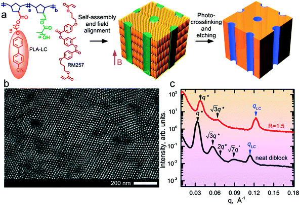
The block copolymer (NBCB12-b-NBPLA3) features a norbornene backbone (NB) with a cyanobiphenyl (CB) based LC block that provides a diamagnetic anisotropy Δχ ∼ 10−6 for field alignment and a chemically degradable minority block based on poly(D,L-lactide) (PLA) side chains for the generation of nanoporous films. The BCP was designed to provide these features, and the PLA side chain molecular weight (3 kg mol−1), as well as the spacer length between the NB backbone and the CB mesogen (12 methylene units), resulted from an iterative empirical molecular design process.24,25 The molecular weight (Mn) of the BCP is 29 kg mol−1. The molecular structure and the schematic of the alignment and etching process to produce nanoporous materials are shown in Fig. 1. The neat system has an LC mass fraction of 0.73 and forms hexagonally packed cylinders of PLA with a d-spacing of 18.8 nm, as shown in Fig. 1 by small-angle X-ray scattering (SAXS) and transmission electron microscopy (TEM). The neat system exhibits a smectic A (SmA) LC mesophase at room temperature with a layer spacing of 5.5 nm.The blend samples were prepared by adding RM257 as a labile species at various stoichiometric ratios, R, representing the molar ratio of RM257 to CB in the blend. At R = 1.5, the highest mesogen content considered, assuming RM257 is selectively sequestered in the NBCB12 LC block, the LC mass fraction (i.e. of the NBCB12 block and the added mesogen) is 0.89. The mass fraction of the BCP is 0.42. Despite the large asymmetry in the composition, the system forms hexagonally packed cylindrical microdomains of PLA at all R considered. As observed previously in side chain LC BCPs,26 the observation of cylindrical microdomains below the canonical composition boundary based on the behavior of linear diblock copolymers is considered a consequence of the stabilization of uniaxial cylindrical microdomains relative to the spherical microdomains due to the uniaxial smectic structure of the LC. The system avoids the formation of spherical microdomains due to the associated elastic distortion energy implied by the preservation of the mesogen anchoring at the block interface. The d-spacing is reduced to 16.5 nm, relative to the neat system. The reduction in d-spacing, despite the addition of material to one phase, suggests that RM257 decreases the segregation strength between the PLA and CB side-chains. The SmA mesophase is retained at room temperature with a slightly smaller layer spacing of 5.1 nm (Fig. 1). The neat sample undergoes an order–disorder transition (ODT) on heating above TODT ∼ 215 °C (ESI,† Fig. S1). At this high temperature however, the material is susceptible to potential thermal degradation and crosslinking of the unsaturated NB backbone, which introduces some uncertainty in the precise determination of TODT. By contrast, TODT ∼ 90 °C for R = 1.5. The strong reduction in TODT on mesogen addition is consistent with the decrease in the interaction strength inferred from the reduction in d-spacing.
A combination of differential scanning calorimetry (DSC) and SAXS data (ESI,† Fig. S2) suggests that the neat system transitions directly from isotropic (I) to SmA at around 80 °C on cooling, but the mesogen blended samples exhibit a nematic (N) window before forming the SmA phase, and that the window broadens on increasing the mesogen content. For R = 1.5, TN–SmA ∼ 70 °C. Additionally, the blended samples undergo a N–Cr (crystal) transition, with the R = 1.5 sample crystallizing at Tx ∼ 55 °C. Temperature dependent polarized optical microscopy (POM) results are in good agreement with these findings, and show a fluid-like nematic texture for R = 1.5 (ESI,† Fig. S3).
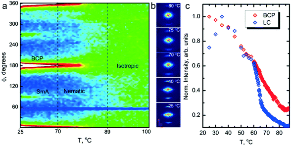
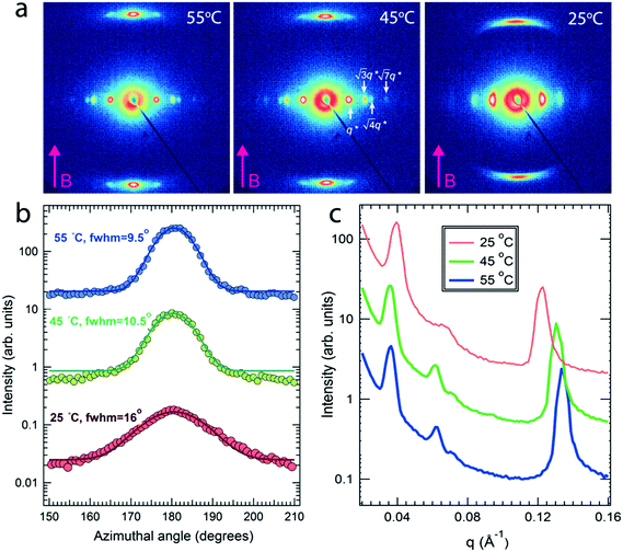
Field alignment experiments were first performed in a superconducting magnet by cooling the samples from an elevated temperature nominally above ODT, to room temperature, at a prescribed rate. The superconducting magnet is coupled to a SAXS system, for in situ observation of the alignment response. No alignment was observed in the neat system, even on application of the largest field accessible, 6 T. By contrast, R = 1.5 blend samples aligned readily at 1 T, at a cooling rate of 0.5 °C min−1. Data are shown in Fig. 2. The system is weakly-segregated (Bragg peaks are broad in q), but modestly well-aligned (the scattered intensity is visibly concentrated azimuthally) in the nematic state just below the ODT. Cooling into the SmA state at ∼70 °C brings a sharp upturn in the scattered intensity and an enhancement of the alignment quality. The alignment improves on continued cooling, but then deteriorates at temperatures below ∼45 °C. This deterioration is linked to mesogen crystallization. The adverse effect of crystallization is shown in the temperature dependent SAXS data shown in Fig. 3, where there is a clear reduction in alignment quality on cooling below the crystallization temperature as evidenced by the azimuthal broadening of the primary BCP Bragg peak and the loss of higher order peaks. This behavior is analogous to that seen in semi-crystalline BCPs, which often suffer from a decrease in mesophase order due to crystallization of one block.27–29 The fact that the disruption occurs in the present case despite the glassy nature of PLA at the temperatures of interest may be due to the fact that PLA forms a discrete phase and that the LC is continuous. Experiments performed at different field strengths (at a fixed rate of 0.5 °C min−1) show that the alignment saturates at ∼0.5 T (ESI,† Fig. S4). Conversely, the cooling rate dependent experiments at a fixed field of 1 T show little rate dependence for cooling rates below ∼1 °C min−1 (ESI,† Fig. S5).
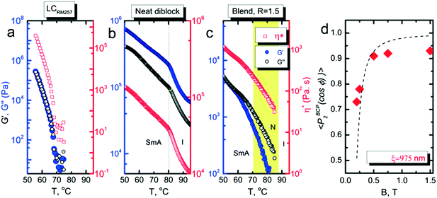
We investigated the dependence of the alignment quality on the mesogen content at intermediate compositions. The R = 0.9 sample aligned readily at 1 T, at a cooling rate of 0.5 °C min−1, but no alignment was observed under these conditions for R = 0.75 (Fig. 4). The ability to align BCP mesophases rests on the appropriate magnitude of the product of the grain volume, the magnetic susceptibility anisotropy and the square of the field strength. Kinetic considerations regarding the viscosity of the system, as well as the grain growth behavior, are also important. Typically, field alignment is most effective when the ODT and the formation of the LC state (nematic or smectic) that provides the magnetic susceptibility anisotropy are effectively coincident. When TODT appreciably exceeds TLC, although the energetics may favor the formation of an aligned state at T < TLC, the high viscosity of the system well below the order–disorder temperature effectively prohibits alignment on the experimentally accessible timescales. For R = 1.5, TODT and TN–I are near-coincident at ∼90 °C, whereas for the neat system ΔT = TODT − TN–I is ∼135 °C. DSC and SAXS data show that TODT decreases sharply while TLC (TN–I) increases modestly, on increasing the quantity of free RM257 mesogens in the system, with ΔT approximately 85 °C and 45 °C for R = 0.75 and R = 0.9, respectively. As with the neat BCP, the potential for crosslinking at elevated temperatures (in the case of the backbone as well as the added mesogen) introduces some uncertainty in the precise determination of TODT. We surmise that below R = 0.9, an increasing disparity between ODT and LC transitions, as well as decreasing mobility overall, limits the ability of the system to align at the low field strength of 1 T. The role of molecular mobility as enhanced by the presence of the small molecule additive is underscored by the complex viscosities of the neat sample and R = 1.5 blend. As shown in Fig. 5(a–c), the complex viscosity of the blend is over 3 orders of magnitude smaller than the neat diblock in the vicinities of their LC transitions, I–SmA and I–N, for the neat and blend samples, respectively.
The characteristic grain size was estimated from the field-dependent alignment. As shown in Fig. 5d, a fit of data for R = 1.5 indicates that the grains are roughly 1 μm in size. While we cannot make a comparable estimate of the grain size of the neat system, 1 μm is significantly larger than that typically encountered in most BCPs. It is likely that the presence of the labile mesogens contributes to the alignment response not just by enhancing the mobility of the system, but also by encouraging the growth of larger grains during ordering. The apparent saturation in the alignment quality at P2 ∼ 0.93 is an artifact due to crystallization induced disruption of the alignment of the BCP. Data measured above the crystallization temperature hews more closely to the expected form, and provides a similar estimate for the grain size, 925 nm for R = 1.2 (ESI,† Fig. S6).
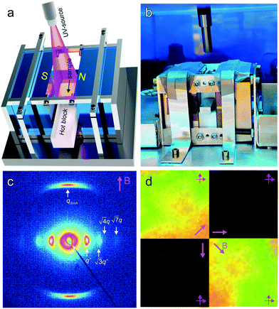
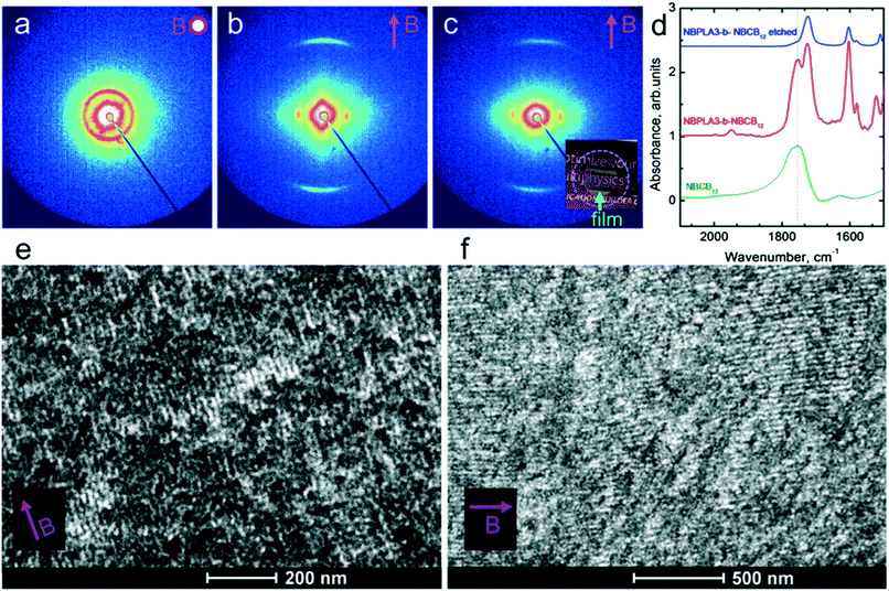
The saturation of alignment for R = 1.5 at 0.5 T is noteworthy as such low fields are easily accessible using low cost permanent magnets. Field alignment experiments were performed in custom apparatus that used 2 opposing neodymium magnets to provide a ∼0.75 T field in the gap between the magnet faces (Fig. 6). A UV source was included to permit the crosslinking of the samples. The SAXS data are indicative of the formation of a well-aligned material and the uniformity of the dark/bright contrast in the polarized optical microscopy (POM) images shows that the alignment is uniform over the field of view of the microscope. The samples were crosslinked by UV exposure after alignment and then wet-etched in a basic solution (0.5 M NaOH in 60/40 H2O/MeOH solution for 24 h). SAXS data show excellent preservation of the anisotropic texture of the sample after etching (Fig. 7b and c), while the strong reduction in the absorbance in the carbonyl region around 1750 cm−1 in FTIR data indicates effective etching of PLA (Fig. 7d). The TEM images taken before and after etching demonstrate that the removal of the PLA chains results in a nanoporous material, as evidenced by the contrast in the non-stained etched samples (Fig. 7f). Here, the free mesogens are a 50/50 molar blend of RM257 and 4′-(hexyloxy)-4-biphenylcarbonitrile (6OCB). 6OCB acts effectively to suppress the RM257 crystallization, which would otherwise obscure the morphology in TEM.
The directed self-assembly and etch selectivity of BCP microdomains have been utilized to create high-performance nano- and ultra-filtration membranes11,30 and templates for the synthesis or deposition of inorganic nanomaterials31–34 or for pattern transfer in BCP lithography.5,6,31,35 The ease of etching of poly(lactide) chains has made PLA-based BCPs a target for such application, in addition to commonly used poly(methylmethacrylate) (PMMA) based systems. It is worth noting that for membrane applications it is necessary to ensure the continuity of vertical microdomain alignment in thin films to both surfaces, as well as to engineer methods for the fabrication of such aligned structures on macroporous mechanical supports. Microdomain continuity considerations also apply for BCP lithography. Nevertheless, the demonstration of facile alignment and etching reported here represents promising starting points in addressing the aforementioned applications.
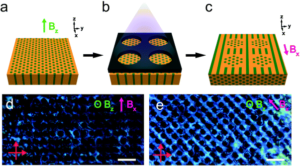
The reactivity of the NB backbone and the RM257 mesogens offers the potential to pattern the microdomain alignment. Specifically, photocrosslinking fixes the alignment such that heating and cooling above the nominal ODT do not result in orientation loss. Spatially selective illumination using a photomask therefore allows the non-crosslinked regions to be subsequently re-aligned in a different direction, while the exposed crosslinked regions retain the alignment imposed in the first field processing step. This sequential alignment process is demonstrated in the data of Fig. 8. A sample film was aligned using a vertically-applied field (i.e. applied along the film thickness or the z-direction), resulting in cylindrical PLA microdomains oriented normal to the sample surface, i.e. vertically in the film. The sample was then UV-illuminated through a photomask consisting of a square array of 30 μm diameter circular openings, resulting in photocrosslinking of the exposed regions. The sample was thereafter aligned with the field located in the plane of the film (along the x-axis in the schematic), by again heating above the nominal ODT and cooling back to room temperature in the presence of the field.
The resulting pattern of cylinder orientation is shown schematically in Fig. 8c. The associated POM textures in through-thickness views of the sample are shown in Fig. 8d and e, with the arrow indicating the field direction in the second alignment step. The data show that the photocrosslinked regions are dark, independent of the sample orientation relative to the crossed polarizers. This is consistent with the alignment of cylinders in these regions along the optical axis for the through-thickness view. Conversely, the optical transmission of the regions surrounding the crosslinked areas displays a clear dependence on the sample orientation, with maximum brightness observed for the field at 45° relative to the crossed polarizers (Fig. 8e) and minimum brightness when the field is parallel/perpendicular to the polarizer/analyzer (Fig. 8d).
The shape memory effect in monodomain crosslinked LC elastomers produces sample contraction along the director and expansion perpendicular to the director, on passage from the LC to the isotropic state of the system.36–43 Such a passage can be thermally driven, or in some cases, optically stimulated, for example by exploiting the cis–trans isomerization of azobenzene-based mesogens. The dimensional change is completely reversible as subsequent transition back into the LC state recovers the original shape due to the structural memory provided by molecular crosslinking. The shape memory effect in LC elastomers is seen as a versatile and attractive route to generate adaptive materials that are thermally and/or optically responsive. A particularly exciting prospect is the creation of mechanical metamaterials44,45 that display complex stimuli responses encoded by spatially varying mechanical properties, such as the shape memory effect, which are deliberately engineered into the system. Photoalignment methods enable the optical control of the anchoring conditions of LCs in thin films.46 The extension of such methods by photopatterning substrate alignment layers to vary the director orientation of LCs deposited and polymerized on the substrate as advanced recently by White et al.47–49 represents one approach to achieve spatial property variation. Another approach is through the use of programmed topological defects created by engineered microchannels, as advanced by Yang et al.50 The results presented here provide a novel, alternative route for achieving such spatial variation of director orientations, though step-wise magnetic field alignment and photopatterned crosslinking processes. The process is relevant for LC BCPs as well as homopolymer LCs.
Conclusions
In summary, we have demonstrated the ability to direct the self-assembly of mesogen-blended LC BCPs using low strength magnetic fields provided by simple permanent magnets. The low field alignment capability originates from the enhanced mobility of the system due to the presence of labile mesogens. The mesogens both plasticize the system without a loss of LC order, and, importantly, bring the ODT and the LC clearing transition into close proximity, thereby optimizing the tradeoff between increasing the driving force and slowing the dynamics that occur on cooling through the ordering transitions in these materials. Additionally, it is likely that the free mesogens alter the grain growth kinetics such that larger grains are formed, which are more readily aligned at low field strengths. The BCP used here provides a versatile platform for the generation of nanoporous materials by selective etching of PLA domains and for photopatterning alignment by spatially selective photocrosslinking through a photomask. We anticipate that the approach demonstrated here may find application in creating nanoporous materials for filtration, in BCP lithography, and in creating bespoke mechanical metamaterials by exploiting the shape memory effect of aligned LC elastomers. Recent results (Fig. 7e and f) show that the deterioration of alignment due to mesogen crystallization can be conveniently avoided by varying the identity and composition of the labile mesogens, providing a path to the preservation of highly aligned structures at ambient temperatures.Experimental section
Materials
Two macromonomers consisting of norbornenyl end-functionalized with poly(D,L-lactide) (NBPLA3, with Mn = 3 kg mol−1 PLA side chains) and cyanobiphenyl groups (NBCB12, i.e. cyanobiphenyl attached via a 12 methylene spacer) were synthesized based on prior reported procedures.24 Block copolymers were synthesized by sequential ring-opening metathesis polymerization (ROMP) using a modified Grubbs generation II catalyst.51 A representative synthesis of NBCB12-b-NBPLA3 is described below. In separate scintillating vials, monomers NBCB12 (600 mg, 1.20 mmol) and NBPLA3 (226 mg, 0.081 mmol) are dissolved in 10 ml of anhydrous CH2Cl2. Grubbs generation II modified catalysts (22 mg, 0.03 mmol) is then measured in a separate scintillating vial and dissolved in 5 ml of anhydrous CH2Cl2. The monomer and catalyst solution vials are then purged under nitrogen for 10 min to make stock solution. The catalyst solution is transferred to stirring NBCB12 stock solution under inert conditions, and the reaction is allowed to proceed for 15 min at room temperature. After polymerization of the NBCB12 monomer, NBPLA3 monomer stock solution is added to the reaction solution under inert conditions and stirred for another 15 min at room temperature. Polymerization is terminated by adding excess ethyl vinyl ether (1 ml). The resulting polymer is precipitated in methanol and then filtered, followed by drying overnight under vacuum at room temperature. The polymerization reaction is summarized in the ESI,† Fig. S7. The 1H NMR spectrum (Bruker DMX 400 MHz NMR spectrometer) is recorded in CDCl3, and the 7.24 ppm peak is used as an internal standard. NMR data is shown in the ESI,† Fig. S8. Mn (GPC-ELSD) is −29 kg mol−1 and PDI is 1.06, determined by GPC with an ELSD detector, where THF was used as eluent and PS standards are used to construct a conventional calibration.Sample preparation and UV crosslinking
A NBCB12-b-NBPLA3 block copolymer was synthesized by sequential ring-opening metathesis polymerization (ROMP) using a modified Grubbs catalyst second generation (mG2nd) ((H2IMes)-(pyr)2(Cl)2RuCHPh) (ESI†). Nematic liquid crystal RM257 (1,4-bis-[4-(3-acryloyloxypropyloxy)benzoyloxy]-2-methylbenzene) was a generous gift from Teledyne Scientific & Imaging, CA. 4′-(Hexyloxy)-4-biphenylcarbonitrile (6OCB) was obtained from Aldrich and used as received. The BCP and RM257 were separately dissolved in chloroform and mixed in appropriate amounts to yield the desired stoichiometry. The solutions were stirred for 1 h, sonicated to ensure homogeneity, and subsequently filtered by a 0.2 μm PTFE filter. Polymer films and bulk samples were prepared by evaporating the solution at 75 °C and further annealed under vacuum at 80 °C for 10 min. The thicknesses of the samples were 0.5 mm and 1 mm for the permanent magnet and superconducting magnet setups, respectively. UV-induced crosslinking was performed through exposure to a 365 nm source (Uvitron/Sunspot SM) for 30 min at a distance of approximately 5 cm. The samples for UV-crosslinking included a small amount of photoinitiator (∼1 wt% of 2-hydroxy-2-methylpropiophenone).Magnetic field alignment
Neodymium bar magnets were purchased from Applied Magnets. According to the manufacturer the magnet produces a surface field of approx. 1.2 T. Two magnets were arranged in a complementary N–S pole arrangement to create a uniform magnetic field of approx. 0.75 T at the sample position. For the investigation of field and kinetic effects using X-ray scattering measurements, a superconducting magnet (American Magnetics Inc.) was used to access fields ranging from 0 to 6 T. Solid samples were sandwiched between thin Kapton windows on a home built temperature controlled aluminum stage. The samples were heated above order–disorder transition temperature, typically to 100 °C for R = 1.5, and subsequently cooled at the prescribed rates while subjected to the magnetic field.X-ray scattering
In situ X-ray scattering experiments in the presence of magnetic fields were conducted using a Rigaku S-MAX3000 instrument configured with a microfocus source producing Cu Kα radiation at 1.54 Å. The instrument is pinhole collimated to attain a beam diameter of 1.3 mm on the sample plane. For in situ SAXS measurements, the instrument was customized to permit the integration of the superconducting magnet. Scattering was recorded using a 2D gas-wire electronic area detector with a resolution of 1024 × 1024 pixels at a distance of approx. 80 cm from the sample plane, which permits scattering vectors q from 0.015 to 0.21 Å−1. The system was calibrated using the primary peak position (58.38 Å) of the silver behenate standard and the resulting scattering patterns were integrated azimuthally to obtain the intensity, I versus scattering vector, q = (4π/λ)sin![[thin space (1/6-em)]](https://www.rsc.org/images/entities/char_2009.gif) θ, with a scattering angle of 2θ. For the temperature resolved measurements, samples were subjected to a heating or cooling rate of 0.1 °C min−1 and equilibrated for 5 min at each temperature before data collection. 2D SAXS data were processed using SAXS GUI and Irena packages.
θ, with a scattering angle of 2θ. For the temperature resolved measurements, samples were subjected to a heating or cooling rate of 0.1 °C min−1 and equilibrated for 5 min at each temperature before data collection. 2D SAXS data were processed using SAXS GUI and Irena packages.
Transmission electron microscopy
Bulk samples were microtomed (Leica UC7) using a diamond knife to obtain approx. 100 nm thick sections. The sections were retrieved on 200 mesh TEM grids and subsequently stained in RuO4 vapor (0.5 wt% aqueous solution, Electron Microscopy Sciences) for 7 minutes before imaging using a FEI Tecnai Osiris instrument operated at an acceleration voltage of 200 keV.Differential scanning calorimetry (DSC)
The thermal behavior of the system was characterized by DSC (Q200, TA Instruments) using a heating rate of 2 °C min−1 under an inert N2 atmosphere.Polarized optical microscopy (POM)
The alignment (optical anisotropy) of thin film samples was examined by POM using a Zeiss Axio Observer 200M inverted microscope equipped with a Pike CCD camera. The measurements were conducted in transmission under crossed polarizers at 5× magnification. Temperature dependent POM experiments were performed using a Linkam TMS 94 controller with a THMS600 stage.Rheology measurements
Elastic and viscous moduli (G′ and G′′) and complex viscosities (η*) were measured on an ARES-LS1 rheometer (TA Instruments) with 8 mm diameter parallel plates. Dynamic temperature sweep measurements were performed using 2% strain at an angular frequency of 1 rad s−1.Fourier transform infrared (FTIR) measurements
FTIR measurements were conducted by a Nicolet Magna 560 IR spectrometer. Samples were prepared using standard KBr pellet method.Conflicts of interest
There are no conflicts to declare.Acknowledgements
This work was supported by the NSF under DMR-1410568. R. K. acknowledges NSF support under DMR-1507045. C. O. and R. K. acknowledge additional NSF support under CMMI-1246804. The authors thank Mike Degen (Rigaku Inc.) and AMI Inc. for technical support. The facilities used were supported by YINQE and NSF MRSEC DMR-1119826. The central instrumentation facilities at the Institute of Materials Science and Chemistry Department, UConn, are acknowledged.References
- C. M. Bates and F. S. Bates, Macromolecules, 2017, 50, 3–22 CrossRef CAS.
- R. A. Segalman, Mater. Sci. Eng., R, 2005, 48, 191–226 CrossRef.
- C. M. Bates, M. J. Maher, D. W. Janes, C. J. Ellison and C. G. Willson, Macromolecules, 2014, 47, 2–12 CrossRef CAS.
- C. J. Hawker and T. P. Russell, MRS Bull., 2011, 30, 952–966 CrossRef.
- Y. S. Jung and C. A. Ross, Nano Lett., 2007, 7, 2046–2050 CrossRef CAS PubMed.
- M. P. Stoykovich, M. Müller, S. O. Kim, H. H. Solak, E. W. Edwards, J. J. de Pablo and P. F. Nealey, Science, 2005, 308, 1442–1446 CrossRef CAS PubMed.
- V. Abetz, Macromol. Rapid Commun., 2015, 36, 10–22 CrossRef CAS PubMed.
- S. Y. Yang, J.-A. Yang, E.-S. Kim, G. Jeon, E. J. Oh, K. Y. Choi, S. K. Hahn and J. K. Kim, ACS Nano, 2010, 4, 3817–3822 CrossRef CAS PubMed.
- H. Ahn, S. Park, S.-W. Kim, P. J. Yoo, D. Y. Ryu and T. P. Russell, ACS Nano, 2014, 8, 11745–11752 CrossRef CAS PubMed.
- E. A. Jackson and M. A. Hillmyer, ACS Nano, 2010, 4, 3548–3553 CrossRef CAS PubMed.
- M. A. Hillmyer, in Adv. Polym. Sci., ed. V. Abetz, Springer Berlin Heidelberg, Berlin, Heidelberg, 2005, pp. 137–181, DOI:10.1007/12_002.
- Y. Zhang, J. L. Sargent, B. W. Boudouris and W. A. Phillip, J. Appl. Polym. Sci., 2015, 132, 41683 Search PubMed.
- H. Hu, M. Gopinadhan and C. O. Osuji, Soft Matter, 2014, 10, 3867–3889 RSC.
- P. W. Majewski, M. Gopinadhan and C. O. Osuji, J. Polym. Sci., Part B: Polym. Phys., 2012, 50, 2–8 CrossRef CAS.
- Y. Rokhlenko, M. Gopinadhan, C. O. Osuji, K. Zhang, C. S. O'Hern, S. R. Larson, P. Gopalan, P. W. Majewski and K. G. Yager, Phys. Rev. Lett., 2015, 115, 258302 CrossRef PubMed.
- D. Ferri, D. Wolff, J. Springer, O. Francescangeli, M. Laus, A. S. Angeloni, G. Galli and E. Chiellini, J. Polym. Sci., Part B: Polym. Phys., 1998, 36, 21–29 CrossRef CAS.
- C. Osuji, P. J. Ferreira, G. Mao, C. K. Ober, J. B. Vander Sande and E. L. Thomas, Macromolecules, 2004, 37, 9903–9908 CrossRef CAS.
- Y. Tao, H. Zohar, B. D. Olsen and R. A. Segalman, Nano Lett., 2007, 7, 2742–2746 CrossRef CAS PubMed.
- H. Tran, M. Gopinadhan, P. W. Majewski, R. Shade, V. Steffes, C. O. Osuji and L. M. Campos, ACS Nano, 2013, 7, 5514–5521 CrossRef CAS PubMed.
- M. Gopinadhan, P. W. Majewski, E. S. Beach and C. O. Osuji, ACS Macro Lett., 2012, 1, 184–189 CrossRef CAS.
- B. Xu, R. Pinol, M. Nono-Djamen, S. Pensec, P. Keller, P.-A. Albouy, D. Levy and M.-H. Li, Faraday Discuss., 2009, 143, 235–250 RSC.
- Y. Rokhlenko, P. W. Majewski, S. R. Larson, P. Gopalan, K. G. Yager and C. O. Osuji, ACS Macro Lett., 2017, 6, 404–409 CrossRef CAS.
- M. Gopinadhan, P. Deshmukh, Y. Choo, P. W. Majewski, O. Bakajin, M. Elimelech, R. M. Kasi and C. O. Osuji, Adv. Mater., 2014, 26, 5148–5154 CrossRef CAS PubMed.
- P. Deshmukh, M. Gopinadhan, Y. Choo, S. K. Ahn, P. W. Majewski, S. Y. Yoon, O. Bakajin, M. Elimelech, C. O. Osuji and R. M. Kasi, ACS Macro Lett., 2014, 3, 462–466 CrossRef CAS.
- Y. Choo, L. H. Mahajan, M. Gopinadhan, D. Ndaya, P. Deshmukh, R. M. Kasi and C. O. Osuji, Macromolecules, 2015, 48, 8315–8322 CrossRef CAS.
- C. O. Osuji, J. T. Chen, G. Mao, C. K. Ober and E. L. Thomas, Polymer, 2000, 41, 8897–8907 CrossRef CAS.
- W.-N. He and J.-T. Xu, Prog. Polym. Sci., 2012, 37, 1350–1400 CrossRef CAS.
- I. W. Hamley, in Interfaces Crystallization Viscoelasticity, Springer Berlin Heidelberg, Berlin, Heidelberg, 1999, pp. 113–137, DOI:10.1007/3-540-48836-7_2.
- Y.-L. Loo, R. A. Register and A. J. Ryan, Macromolecules, 2002, 35, 2365–2374 CrossRef CAS.
- S. P. Nunes, Macromolecules, 2016, 49, 2905–2916 CrossRef CAS.
- Y.-C. Tseng, Q. Peng, L. E. Ocola, J. W. Elam and S. B. Darling, J. Phys. Chem. C, 2011, 115, 17725–17729 CAS.
- T. Thurn-Albrecht, J. Schotter, G. Kästle, N. Emley, T. Shibauchi, L. Krusin-Elbaum, K. Guarini, C. Black, M. Tuominen and T. Russell, Science, 2000, 290, 2126–2129 CrossRef CAS PubMed.
- J. Y. Cheng, C. Ross, V. H. Chan, E. L. Thomas, R. G. Lammertink and G. J. Vancso, Adv. Mater., 2001, 13, 1174–1178 CrossRef CAS.
- R. Olayo-Valles, M. S. Lund, C. Leighton and M. A. Hillmyer, J. Mater. Chem., 2004, 14, 2729–2731 RSC.
- J. Chai and J. M. Buriak, ACS Nano, 2008, 2, 489–501 CrossRef CAS PubMed.
- S.-k. Ahn, P. Deshmukh, M. Gopinadhan, C. O. Osuji and R. M. Kasi, ACS Nano, 2011, 5, 3085–3095 CrossRef CAS PubMed.
- I. A. Rousseau and P. T. Mather, J. Am. Chem. Soc., 2003, 125, 15300–15301 CrossRef CAS PubMed.
- J. Küpfer and H. Finkelmann, Macromol. Rapid Commun., 1991, 12, 717–726 CrossRef.
- C. Ohm, M. Brehmer and R. Zentel, Adv. Mater., 2010, 22, 3366–3387 CrossRef CAS PubMed.
- P. Beyer, E. M. Terentjev and R. Zentel, Macromol. Rapid Commun., 2007, 28, 1485–1490 CrossRef CAS.
- T. J. White and D. J. Broer, Nat. Mater., 2015, 14, 1087–1098 CrossRef CAS PubMed.
- J. M. Boothby and T. H. Ware, Soft Matter, 2017, 13, 4349–4356 RSC.
- A. Agrawal, T. Yun, S. L. Pesek, W. G. Chapman and R. Verduzco, Soft Matter, 2014, 10, 1411–1415 RSC.
- J.-H. Lee, J. P. Singer and E. L. Thomas, Adv. Mater., 2012, 24, 4782–4810 CrossRef CAS PubMed.
- J. L. Silverberg, A. A. Evans, L. McLeod, R. C. Hayward, T. Hull, C. D. Santangelo and I. Cohen, Science, 2014, 345, 647–650 CrossRef CAS PubMed.
- T. Seki, S. Nagano and M. Hara, Polymer, 2013, 54, 6053–6072 CrossRef CAS.
- B. A. Kowalski, T. C. Guin, A. D. Auguste, N. P. Godman and T. J. White, ACS Macro Lett., 2017, 6, 436–441 CrossRef CAS.
- B. A. Kowalski, V. P. Tondiglia, T. Guin and T. J. White, Soft Matter, 2017, 13, 4335–4340 RSC.
- T. H. Ware, M. E. McConney, J. J. Wie, V. P. Tondiglia and T. J. White, Science, 2015, 347, 982–984 CrossRef CAS PubMed.
- Y. Xia, G. Cedillo-Servin, R. D. Kamien and S. Yang, Adv. Mater., 2016, 28, 9637–9643 CrossRef CAS PubMed.
- J. A. Love, J. P. Morgan, T. M. Trnka and R. H. Grubbs, Angew. Chem., Int. Ed., 2002, 41, 4035–4037 CrossRef CAS PubMed.
Footnotes |
| † Electronic supplementary information (ESI) available. See DOI: 10.1039/c7me00070g |
| ‡ These authors contributed equally. |
| This journal is © The Royal Society of Chemistry 2017 |

