Nanolithography of cylinder forming block copolymers via DSA for semiconductor manufacturing
Yuri
Granik
a and
Andres
Torres
 *b
*b
aMentor A Siemens Business, 46871 Bayside Parkway, Fremont, CA 94538, USA
bMentor A Siemens Business, 8005 SW Boeckman Rd, Wilsonville, OR 97070, USA. E-mail: andres.torres@siemens.com
First published on 7th November 2017
Abstract
To realize the full benefit of directed self-assembly (DSA), it is necessary to understand the interplay between the target structures and the process parameters. In this paper, we cover the reasons as to why a compact model and model-based synthesis are required for graphoepitaxial DSA of cylinder forming block copolymers.
Design, System, ApplicationThis work describes the details of a compact model with the ability to adequately predict BCP cylinder placement and phase transition behavior within a grapho-epitaxial guiding pattern. In addition, this paper describes how such a model can be used in the synthesis and verification of guiding patterns built using a photolithographic process. This is, to our knowledge, the first time a compact model with the ability to process full chip designs is disclosed to the public. |
Introduction
DSA is a compelling technology for printing dense-pitched and low critical-dimension (CD) via/contact layers1,2 because it has the potential to reduce the number of masks and/or the number of processing steps of current state-of-the-art processes. By exploiting the inherent pitch multiplication in DSA, it is possible to generate a single patterning mask that delivers a resolution after assembly and development, which is lower than the diffraction limit of the mask undergoing traditional processing. The self-assembly process described in this work is focused specifically on cylinder forming block copolymers which are directed by guiding structures that utilize confinement (grapho-epitaxy, lithographically printed patterns).The pitch multiplication property of DSA enables the printing of dense contact pitches below the resolvable lithographic pitch using the appropriate molecular composition of two block copolymers and by selecting the correct shapes for the grapho-epitaxy guiding patterns (GPs). Since the chemical composition of the diblock copolymer is invariant in a specific DSA process, the accurate synthesis of GPs for arbitrary contact patterns has become a key bottleneck in the robust assembly of contacts to accurately match the placement of target contact shapes. The existing work on the generation of GP shapes3 is very rudimentary. It first maps groups of contacts into a list of discrete patterns and then selects from a list of pre-characterized GPs to encapsulate each contact group. This alphabet-based GP lookup methodology has several drawbacks.
Very regular 1-D standard cell layout patterns have been assumed in order to increase the probability of mapping contact patterns into the GP alphabet list. However, the majority of full custom cell layouts today still use 2-D styles, thus many contact patterns may not be mapped.
The GP generation in ref. 3 did not consider the effect of post-RET process variations, i.e., the post-RET image of the same alphabet may be different at various locations across the chip.
The key objective of this paper is to describe a general framework for full-chip GP synthesis that directly addresses these drawbacks. Any method attempting to optimize the shape of a GP for accurate contact assembly needs to have the means to accurately predict the locations of assembled contact shapes given the GP as input. Since it is not practical to embed a full-physics DSA simulator directly into GP synthesis due to its prohibitive runtime, we need to ensure that this GP synthesis framework uses a compact DSA model which is accurately calibrated against a chemistry-based DSA simulator or experimental data, delivering sufficiently accurate prediction of both placement and phase transition, at a significantly faster runtime.
Patterning IC designs with a DSA nanolithography process
The number and type of processes required for DSA grapho-epitaxial processes are listed below from physical design to production.DSA Process: Grapho-epitaxy process steps, from design to manufacturing
| Input: | Desired input layout |
| Output: | Etched holes defining contact/via locations on wafer |
| 1 | L = Intended layout; |
| 2 | GP = Guiding pattern for intended layout L; |
| 3 | OPC = Target mask shapes for GP printing; |
| 4 | GPo = Optical simulation of post OPC contour |
| 5 | DSA = DSA simulation of GPo |
| 6 | if DSA ≠ L then go to step 2 |
| 7 | GPm = Mask set for guiding pattern |
| 8 | Spin coat resist |
| 9 | Expose GPm |
| 10 | Develop |
| 11 | Resist freeze |
| 12 | Surface modification (brush) |
| 13 | Spin coat BCP |
| 14 | Anneal |
| 15 | PMMA etch |
| 16 | Substrate etch |
Compact model
DSA technology is intended to improve printing of contacts in integrated circuits (ICs). The abundance of contacts is astounding in modern IC designs. Billions of contacts have to be reliably printed within margins of technological tolerances. In addition to this obvious populational complexity, the contacts are generally designed to be placed in random locations across the surface of a chip and yet close to each other (that is why logic ICs are represented by what is called “random logic layouts”). Proximal interactions between closely placed contacts are diverse. This makes each contact unique because it is hard to find repeatable configurations of guiding patterns within which the contacts can be treated in the same manner.These two complications – the abundance and randomness – prohibit the usage of first-principles modelling like Monte-Carlo molecular dynamics, Self-Consistent Field Theory (SCFT), dissipative particle dynamics, Ginzburg–Landau theory, derived from the Ohta–Kawasaki model, etc. Indeed, let us assume that a first-principles simulation of the contact forming process for a single guiding pattern takes 1 hour on one CPU. Then it takes on order of 109 hours to simulate the whole chip. Even if this massive computational job is parallelized to 10![[thin space (1/6-em)]](https://www.rsc.org/images/entities/char_2009.gif) 000 CPUs, we still have to wait 100 years for the simulations to be completed.
000 CPUs, we still have to wait 100 years for the simulations to be completed.
Below we present Compact DSA model version year 2013 (CDSA-13 model) that is intended to predict the final positions of DSA cylinders across the whole IC chip in hours. It is obvious that in order to achieve this desired millions time speedup in comparison with first-principles modelling methods we have to dramatically simplify the statement of the problem while still capturing the essence of DSA effects.
The following methodological principles and assumptions guided the CDSA-13 design stage:
1. DSA systems are characterized by a large number of state variables, or degrees of freedom. We tried to reduce the number of state variables to the bare minimum.
2. We accept and adopt the full energy of the polymer (within the confines of a guiding pattern) as a fundamental characteristic of the system. In the final state, the energy is necessarily at the minimum.
3. We assume that the process conditions are uniform across the chip, so that, for example, the annealing conditions do not vary from one place to another.
4. We generally are not interested in how the contacts react to changes in process conditions, but rather assume fixed, controlled, and carefully selected process conditions under which all – or at least the majority – of cylinders are reliably formed without defects.
5. We are not interested in the complete dynamics of polymer assemblage from an amorphous to a fully segregated state, but rather concentrate on its final phase, when the polymer is in a near-stable state.
Prior work
The absolute majority of numerous DSA modelling studies are devoted to the advancement of first-principles based methods and their numerical implementations. These studies usually concentrate on grapho-epitaxy either for isolated contacts or doublets, and are successfully utilized in engineering practice for selecting suitable process conditions and materials. In contrast, the reference list for compact DSA modelling is minute. Besides publications by our research team, we acknowledge Liu,4 Qin,5 and Latypov.6Liu4 presented simulation results of some compact DSA model without offering an explanation as to how this model actually works. This model achieves 250![[thin space (1/6-em)]](https://www.rsc.org/images/entities/char_2009.gif) 000 times speedup in comparison with Monte-Carlo simulations. Qin5 solved the Cahn–Hilliard non-linear partial differential equation with a particular form of Landau–Ginzburg free energy. The typical runtime is 2000 seconds, or half an hour, which is too large to consider this approach appropriate in compact modelling. Latypov6 promoted the idea of using linearized SCFT equations for compact modelling, but this suggestion has not resulted in a completely functioning model.
000 times speedup in comparison with Monte-Carlo simulations. Qin5 solved the Cahn–Hilliard non-linear partial differential equation with a particular form of Landau–Ginzburg free energy. The typical runtime is 2000 seconds, or half an hour, which is too large to consider this approach appropriate in compact modelling. Latypov6 promoted the idea of using linearized SCFT equations for compact modelling, but this suggestion has not resulted in a completely functioning model.
Compact model description
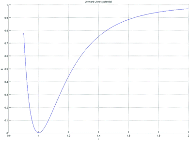
In CDSA-13, we assume that the DSA process ends in a full phase separation with the final contacts (as 3D vertically standing cylinders) all being circular and of the same size. We ignore the depth effects along the vertical z coordinate, i.e. assume that the morphology is strictly cylindrical and without 3D defects. The CDSA-13 model is intended to predict the final positions of contacts within a single guiding pattern. The contacts are assumed to be formed by the minority phase A, while the remaining space between the cylinders and walls of a guiding pattern are filled with the majority phase B (Fig. 1–4).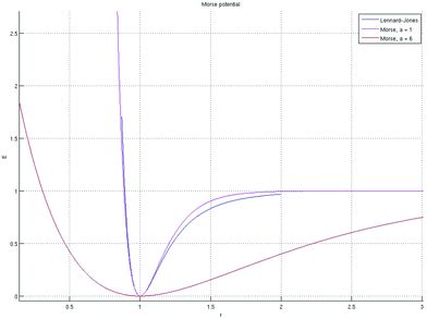 | ||
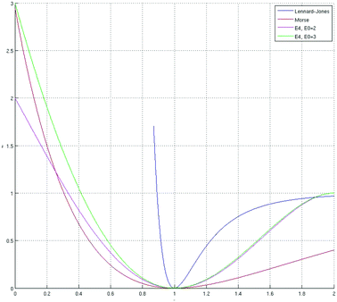
| Fig. 2 Morse potential is shown in red and magenta for two different values of a. The Lennard-Jones potential is drawn in blue. | ||
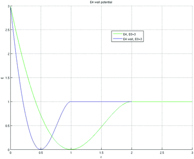 | ||
| Fig. 4 Potential of the wall Pwall is shown in blue, and internal potential energy is shown in green, both for P0 = 3. | ||
The Cartesian coordinates of the centers of the minority phase A and, thus, the state of the whole system, are determined by the set of points
 | (1) |
We consider the guiding pattern containing contacts to be an isolated physical system. Its full energy is assumed to be a sum of the potential energy of interactions between cylinders (we call it internal energy Einternal) and the potential energy of interactions between the sidewalls and the cylinders (we call it external energy Eexternal). Here we ignore the kinetic energy of polymer chains, thermal dissipation, and other effects that are deemed to be secondary.
By introducing the pair-wise distances between centers of contacts,
 | (2) |
 | (3) |
The shape of the potential P should deliver a minimum at the locations ri,j = q
| P′(r)|r = q = 0 | (4) |
| P′′(r)|r = q > 0 | (5) |
| P(r) ≥ 0 | (6) |
| P(r)|r = q = 0 | (7) |
Here, the first equation, eqn (6), ensures that the potential energy is always positive, and the second one, eqn (7), fixes the arbitrary constant in the energy definition. For large distances, the potential should level off asymptotically, so that
 | (8) |
There are numerous standard potentials (mainly coming from the physics of multi-body problems) that satisfy these requirements. First, we mention the Lennard-Jones potential:
 | (9) |
This potential is very strong in its repulsive part r < 1. The second widely used potential is the Morse potential:
| P(r) = [1 − e−a(r−q)]2 | (10) |
Unlike the Lennard-Jones potential, this one can be adjusted to define the width of the well a.
We can synthesize a polynomial potential that is softer than the Lennard-Jones potential and is more spring-like (remember that in Hooke's law the spring potential is parabolic), if we use the following P4 form for the potential:
| P(r) ≡ P4(ρ) = P0 + c1ρ + c2ρ2 + c3ρ3 + c4ρ4 | (11) |
 . To find coefficients cj, we set forth the following conditions that follow from eqn (6)–(8)
 | (12) |
The following polynomial satisfies the above conditions:
 | (13) |
| 0 ≤ ρ ≤ 2 | (14) |
| P4(ρ) = 1, for ρ > 2 | (15) |
To account for the sidewalls, we introduce the energy that is produced by the interaction of the guiding pattern with the contacts within it:
 | (16) |
| si(s) = |ri − r(s)| | (17) |
The elementary potential Pwall should be chosen in such a way that the minimum is achieved at si = q/2. If we use P4, then
| Pwall(si) = P4(2ρi), ρi = si/q | (18) |
By combining the internal and external energies, we get the following final expression for the total energy of the DSA polymer within the confines of one guiding pattern:
 | (19) |
In the stationary state, this energy achieves a minimum while maintaining cylinders within the guiding pattern G:
 | (20) |
These are the main equations that define the CDSA-13 model. From a formal mathematical standpoint, they constitute a constrained non-linear optimization problem for variables (xj, yj) as centers of the contacts within one guiding pattern. This problem can be numerically solved by standard gradient-based methods. A typical optimization method for a guiding pattern with a handful of contacts converges on the solution in one hundredth of a second.
CDSA-13 model calibration
Fig. 5 shows how the compact model error responded to the value of the natural period of the block copolymer (q). Because of the nature of the multi-dimensional calibration process, there is denser sampling near the 35 nm value, which corresponds to the value of the natural period of the BCP of interest.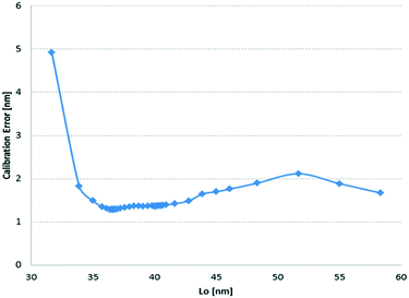 | ||
| Fig. 5 Calibration error as a function of the natural period model parameter (Lo) of the diblock copolymer. | ||
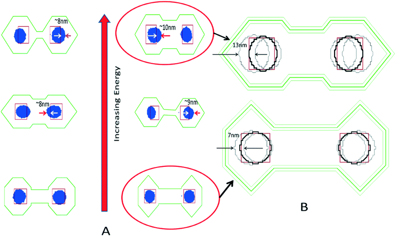
But while Fig. 5 depicts the ability of the compact model to predict proper error placement, Fig. 6 shows how the models are able to correlate the phase transition behavior with the total energy (ETotal) provided by the compact model.
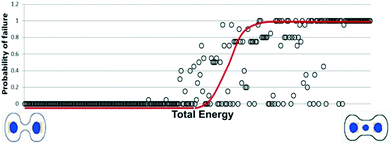 | ||
| Fig. 6 As the GP total energy increases, the probability of failure and phase transition increases as well. | ||
Each individual point corresponds to one guiding pattern simulated 100 times. The probability of failure is calculated by determining how many out of those 100 random simulations the guiding pattern exhibited a polymer configuration other than intended. When the cylinders were not perfect, or when new cylinders appeared, the discrete simulation would be considered to be in-phase transition. Only if the right number of cylinders appeared in the guiding pattern, with enough symmetry, were they considered as not being in phase transition. In other words, the compact model is able to predict with sufficient accuracy the regions that are robustly assembled, and it provides a mechanism (i.e. ETotal) to compare the quality of assembly between two different guiding patterns, without the need for performing expensive full physics simulations.
After describing the model, and its properties, the next sections are focused on using the compact model to deliver robust guiding pattern shapes.
Guiding pattern synthesis
Overall flow
Our proposed mask synthesis data flow consists of four main operations as depicted in Fig. 7.Given an input layout, the first step is to partition the target contacts into DSA compliant groups. After successful contact layer partitioning into DSA compliant groups, the next step is to synthesize a GP for each group. Once all the groups have their individual GP computed, the next step is to perform mask synthesis of each GP in a way that the patterned GP is within acceptable tolerances of its target shape.
Because layout context and process window variations in the manufacturing process do not guarantee perfect transfer of the intended GP targets,7 a process window aware DSA simulation, considering a family of GP shapes, is performed in order to verify that the assembled contacts are within the target contact placement and shape requirements.
Layout decomposition and grouping
Each guiding pattern (GP) group is subject to the following constraints:• q ≤ dc ≤ dmax: Within all groups in the same patterning step, dc is the distance between adjacent contacts; q and dmax are the pitch bounds at which the assembly is robust.
• dg > L: The distance between each DSA contact group (dg) needs to be at least L away from each other, where L is the minimum resolvable single patterning distance.
• Mcg ≤ 4: The maximum number of contacts per group. This constraint is required to prevent exploring unstable assembly conditions for PS-PMMA BCP. Mcg may be different for high-χ materials.
• O = 0°; O = 90°: By considering practical limitations of the lithography process, 193 nm immersion lithography requires groups to be oriented (O) at 0° and/or 90° angles whereas EUV lithography enables 0° ≥ O ≥ 90°.
• Nn ≤ 2: The maximum number of neighbors (Nn) within the distance dc that any contact can have is limited to less than two. This means that no branched guiding patterns are allowed since confinement is reduced under those configurations, reducing the robustness of the assembly process.
Guiding pattern synthesis
The first required constraint to enable proper and robust assembly is the volume fraction (f) of the diblock copolymer. | (21) |
 | (22) |
The previous equation only allows the required amount of material to be present in each GP, but alone is not sufficient to guarantee proper cylinder placement or stable assembly.
In conjunction with the volume fraction constraint, two additional optimization objectives are defined. The first one is to minimize the placement error (pe) for every contact in every group
| Minimize(pei) | (23) |
| Minimize(Etotal) | (24) |
In the following sections, we will define the algorithms describing the simultaneous optimization of placement error and total energy, thus providing the means of robust assembly at the desired location.
It is pertinent to highlight at this point that due to the nature of the compact model, it is possible that artificially high energies will arise when the contacts are in tension or compression and away from their natural state. In a formal simulator, these high energies lead to the re-assembly of the different materials, while this formulation attempts to find the lowest energy state given the cylinder count constraints. Far from being a disadvantage, we use this characteristic as a desirable property of the compact model.
Backbone formation
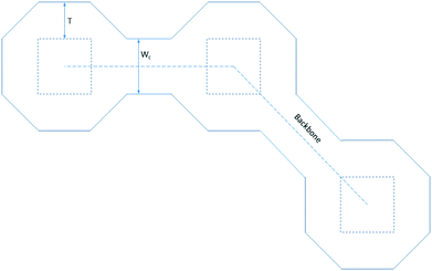
We start by creating a backbone, which is defined as the shortest path visiting each contact in a group exactly once. The backbone prevents cycles and branches in the resulting GP shapes. This problem is recognized as an application of the Travelling Salesman Problem (TSP). Because the contact groups are strings due to the grouping constraints, the TSP can be mapped to a simpler class of Euclidean TSP which can be solved in O(N(log![[thin space (1/6-em)]](https://www.rsc.org/images/entities/char_2009.gif) N)), where N is the number of contacts within the GP contact group under consideration.
N)), where N is the number of contacts within the GP contact group under consideration.
GP shape generation
After the backbone has been created, a seed shape obeying the volume fraction constraint is defined. The seed shape is used as a starting point to an iterative process computing the error placement at every iteration, while making sure that every new GP meets the area constraint defined by the volume fraction (Fig. 8).T is the initial sizing factor growing the GP to meet the required area constraint. Wc is the user specified connector width between octagons. W is the contact width, assuming square contacts.
The seed shape generation is then defined to achieve the target GP area constraint:
 | (25) |
Algorithm 1: Generating a candidate GP shape
| Input: | Vector of transformed target contact shapes S |
| Output: | GP shape satisfying the volume fraction equation |
| 1 | A = Target area; |
| 2 | T = Initial sizing factor; |
| 3 | C = list of N − 1 trapezoidal connectors between N contacts in S; |
| 4 | A′ = Area of the GP shape computed from (S, C) by sizing S by T; |
| 5 | step = small step size by which T is modified; |
| 6 | if A ≤ A then |
| 7 | dir = +1 |
| 8 | else |
| 9 | dir = −1 |
| 10 | While |A − A′| ≤ ε do |
| 11 | T = T + dir × step; |
Unfortunately, for robust assembly, meeting the volume fraction alone is not enough. The GP also needs to assemble the cylinders at the right location, and far away from the order-phase transition.
Fixed point iteration PE optimization
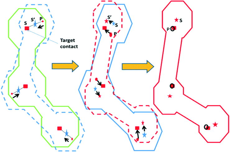
Let us represent the original target contact locations by the vector S* consisting of a set of N points corresponding to the centers of the drawn targets. We use the following fixed point iteration formulation where the next solution vector S′ is given by:| S′ = S − γ(P − S*) | (26) |
The intuition behind the above formulation is that the term (P − S*) determines the direction in which the current solution must move in order to converge on the ideal locations S*. The trajectory of a specific GP convergence is depicted in Fig. 9. We iterate until we have converged on a solution vector within an acceptable margin of error.
Algorithm 2: Minimizing placement error
| Input: | Vector of target contact locations S*, compact model (CM) |
| Output: | Optimized GP |
| 1 | B = generate the backbone by solving the TSP; |
| 2 | S = S′ = S*; |
| 3 | GP(S) = generate the initial GP shape using algorithm 1; |
| 4 | P(S) = CM predicted contact locations using GP(S); |
| 5 | While ε ≤ |P(S′) − S*| do |
| 6 | If |P(S′) − S*| > |P(S) − S*| then |
| 7 | Break due to divergent behavior |
| 8 | else |
| 9 | S = S′; |
| 10 | S′ = S − γ(P(S) − S*); |
| 11 | GP(S′) = generate the GP shape using algorithm 1; |
| 12 | P(S′) = CM predicted contact locations using GP(S′) |
An algorithm to generate a GP that minimizes the PE between the assembled and drawn target contacts is specified in algorithm 2. The input to this algorithm is a set of target contact locations and the output is an encapsulating GP that minimizes the PE.
Energy minimization for robust assembly
We have up to this point shown a method to synthesize GPs considering only PE as an optimization objective. For robust assembly optimization, the error placement metric is not enough, as it does not provide an idea of how sensitive the placement of the cylinders will be to the guiding pattern variations. In order to achieve more robust GPs, we propose a method that finds GPs in a way that the cylinders are in target while also as far away as possible from their phase transition. We accomplish this by noticing that robust assembly happens at lower values of ETotal, therefore when deciding between two GPs with similar nominal edge placement, we choose the guiding the pattern with the lowest total energy.Fig. 6 shows that there is a direct correlation between the total energy (ETotal) and robust assembly. Each data point in the scatter plot is a GP shape ordered by increasing the ETotal in the X-axis and increasing the probability of failure in the Y-axis. The probability of failure was measured by running 100 Monte-Carlo simulations for each GP and measuring the shape deviation in three dimensions from the ideal cylindrical shape for each target contact in each simulation. If a failure was encountered for every run for a GP then the probability of failure was 1 and if there was no failure in any of the runs then the GP was considered robust with a probability of failure of zero. Each GP was expected to assemble exactly two contacts. In Fig. 6, the GP with the highest ETotal on the extreme right assembles a third contact at the center instead of the two required contacts. Hence, we now have the motivation for using ETotal as a second metric for generating robust GPs.
Now that we have a method to generate a GP optimized for PE we will enumerate a method that simultaneously optimizes both PE and ETotal. Prior work8 on the Template Error Enhanced Factor (TEEF) metric has shown that the robustness of assembly is most sensitive to the CDTY and CDTBW parameters in the TEEF matrix. CDTY corresponds to the size of the guiding pattern perpendicular to the backbone, and CDTBW corresponds to the minimum connector width.
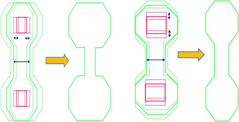
Our seed GP shapes are obtained by transforming the original contacts through a series of corner rounding and sizing operations, and then merging the transformed shapes with fixed width connectors along the backbone while maintaining the volume fraction constraint. Since it is the contact that forms the seed for the final GP shape, we can further transform the seed contact to enable us to sweep through various aspect ratios of the octagonal sections. The changing aspect ratios enable us to sweep through the TEEF parameter CDTY. In addition, the other TEEF sensitive parameter CDTBW directly maps onto our connector width parameter Wc. We incrementally sweep through various contact aspect ratios and connector widths and use algorithm 2 to minimize the PE for each GP shape configuration and choose the configuration with minimum ETotal returned from our compact model.
Fig. 10 depicts the GP shape transformations for finding a GP with minimum ETotal while maintaining the volume fraction constraint for each intermediate GP shape.
Algorithm 3: Minimizing GP energy
Algorithm 3 shows our overall methodology for simultaneous optimization of both PE and energy. It has an outer loop that sweeps through incrementally varying connector widths and an inner loop which sweeps through incrementally varying contact aspect ratios creating virtual contact seeds for the resulting GP shapes while still maintaining the area fraction constraint corresponding to the original square contacts. It shall be noted that we could have exited the above loops at inflection points but our experience has been that the correlation function between TEEF and energy does not have a single extremal point, but our objective is to find the global minimum and hence the exhaustive search. In practice, algorithm 3 can be provided with a starting exploration point from which to begin the search based on regression analysis of prior data.
Mask synthesis of GP and verification
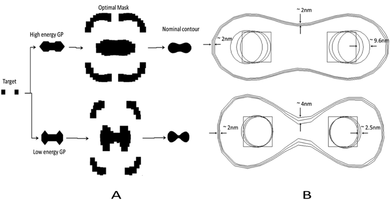
One of the main goals of improving the robustness of the assembly process to GP variations is to consider process variations affecting the lithographic process. Fig. 11 shows the target holes within the synthesized groups considering the optimal (low energy) GP, and a large energy solution for the same target pitch. Notice how in this decoupled flow, the final nominal contour deviates from the ideal GP, raising the importance of generating a GP that is more robust to fluctuations in its shape with respect to the assembly process.The actual holes after assembly resulting from the GP produced by a 193 nm immersion process are shown in Fig. 12B. After introducing a 40 nm defocus and ±2% dose variation, the GPs produce very different error placement results.
While the average GP variation for most of the patterns is within a 2 nm range, even 4 nm range differences in the GP are able to be absorbed by the low-energy GP configuration.
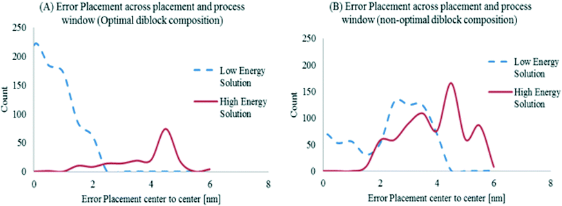
In contrast, the GP with higher nominal energy shows indeed a higher sensitivity in error placement due to the GP variation. Error placement was only computed when the model returned a valid configuration. Notice how the guiding pattern obtained by considering the approach proposed in this work delivers a smaller error placement for the same process variations.
Fig. 13 shows how even if the optimal methodology is used, if the natural period of the material is not commensurable to the desired pitch, the error placement is significantly higher when compared to the solution when both the guiding pattern and BCP composition are optimized to find the more robust guiding pattern shape.
Conclusions
This paper presents a compact model for cylindrical DSA grapho-epitaxial processes and a companion model-based GP synthesis algorithm with a focus on accurate placement, robust shape fidelity and resiliency to post-RET process variations. We first introduced a DSA-centric mask synthesis which included a post-RET verification step of our GPs that maintained accurate placement and robust shape formation resiliency through process variations.In our experiments, the performance of the model is capable to process a full chip with existing OPC-class computing platforms. The performance ranges from 1 to 40 CPU-hours per millimetre squared, which places it within the same range of traditional computational lithography tools used in production.
We proposed a model based GP synthesis algorithm that uses a novel compact model to predict the next solution in a fixed point iteration approach. Our synthesis algorithm also included GP shape exploration to search for both a minimum energy and a minimum PE shape configuration. We then provided the quality of results for a specific compact model calibrated for a specific process along with correlation of internal GP energy with the TEEF metric which provides a measure of the robustness of the assembly. This work provides an avenue to understand the observed experimental displacement error reported by most research groups, and it provides an avenue to reduce it by finding the guiding pattern solution with minimum TEEF.
Conflicts of interest
There are no conflicts to declare.Acknowledgements
The authors would like to acknowledge Joydeep Mitra, Polina Krasnova, and Daman Khaira for the contributions to this paper, as well as IMEC and PLACYD member companies for the verification of the technology presented here.References
- Y. Ma, J. A. Torres, G. Fenger, et al., Challenges and opportunities in applying grapho-epitaxy dsa lithography to metal cut and contact/vi applications, in 30th European Mask and Lithography Conference, International Society for Optics and Photonics, 2014 Search PubMed.
- Y. Badr, J. A. Torres and P. Gupta, Mask assignment and synthesis of dsa-mp hybrid lithography for sub-7nm contacts/vías, in Design Automation Conference, 2015 Search PubMed.
- H. Yi, X. Y. Bao and R. Tiberio, et al., A general design strategy for block copolymer directed self-assembly patterning of integrated circuits contact holes using and alphabet approach, Nano Lett., 2015, 15(2), 805–812 CrossRef CAS PubMed.
- C. Liu, J. Pitera, N. Lafferty, et al., Progress towards the integration of optical proximity correction and directed self-assembly of block copolymers with graphoepitaxy, Proc. SPIE 8323, Alternative Lithographic Technologies IV, 83230X (March 1, 2012) Search PubMed.
- J. Qin, G. S. Khaira and Y. Su, et al., Evolutionary pattern design for copolymer directed self-assembly, Soft Matter, 2013,(48), 11467–11472 RSC.
- A. Latypov, Computational solution of inverse directed self-assembly problem, Proc. SPIE 8680, Alternative Lithographic Technologies V, 86800Z (March 26, 2013), 2014 Search PubMed.
- R. Gronheid and P. Nealey, Directed Self-assembly of Block Co-polymers for Nano-manufacturing, 2015 Search PubMed.
- Y. Ma, J. A. Torres, G. Fenger, et al., Directed Self-Assembly (DSA) grapho-epitaxy template generation with immersion lithography, in Proc. SPIE 9423, Alternative Lithographic Technologies VIII, 942396, 2015 Search PubMed.
| This journal is © The Royal Society of Chemistry 2017 |

