Preparation and properties of thermally conductive polyimide/boron nitride composites
Na Yanga,
Chen Xua,
Jun Houa,
Yanmei Yaoa,
Qingxin Zhanga,
Maryam E. Gramib,
Lianqi Hec,
Nongyue Wanga and
Xiongwei Qu*a
aInstitute of Polymer Science and Engineering, School of Chemical Engineering, Hebei University of Technology, Tianjin, P. R. China. E-mail: xwqu@hebut.edu.cn
bComposite Materials Engineering, Winona State University, Winona, Minnesota, USA
cOuya Hose Corporation, Heshui, Hebei, P. R. China
First published on 8th February 2016
Abstract
Polyimide (PI) has been widely used as a preferred packaging matrix material due to its low dielectricity, outstanding insulation and excellent thermal stability. Hexagonal boron nitride (h-BN) microparticles were functionalized with a silane coupling agent, 3-glycidyloxypropyltrimethoxy silane (γ-MPS), to improve the interface action with the PI matrix. The modified h-BN (m-BN) particles were used to fabricate the PI/m-BN composites with enhanced thermal conductivity by in situ polymerization. The Fourier transform infrared (FTIR) spectra, thermo-gravimetric analysis (TGA), transmission electron microscopy (TEM) and contact angle test proved that γ-MPS coupling agent molecules had been chemically grafted onto the h-BN surface. In addition, the effects of the m-BN content on the thermal conductivity of PI/m-BN composites were investigated. The composite obtained with 40 wt% m-BN particle loading presented a thermal conductivity of 0.748 W m−1 K−1, 4.6 times higher than that of pure PI. Meanwhile, the fabricated PI/m-BN composites retained excellent electrical insulation and thermal stability. The glass transition temperature values of the PI/m-BN composites decreased slightly while the storage modulus improved with the increase of the m-BN content. These results showed that PI/m-BN composites may offer new applications in the microelectronic industry because future substrate materials require effective heat dissipation.
Introduction
Along with the rapid development of science, technology and the worldwide economy, electrical materials have been unable to meet the requirements to dissipate the emitting heat because of their increasing integration. As polymer materials have the advantages of excellent electrical resistivity, fatigue resistance, good chemical resistance and easy processing, they are progressively utilized in aerospace, packaging matrix materials, electronic information, heat engineering and other fields. But the thermal conductivity of traditional polymeric materials is generally low, most falls in between 0.1 and 0.25 W m−1 K−1,1,2 which limits their wide use as thermally conductive materials in industry.3 Therefore, polymer composites with high thermal conductivity and electrically insulating properties have attracted increasing interests to solve heat-dissipation problems.To date, two methods are used to improve thermal conductivity of polymer materials. One is to synthesize intrinsic thermal conductive polymer materials with π-conjugated bond, which heat conduction is via the electronic heat conduction mechanism or the phonon mechanism for heat conduction by improving the crystallization of polymer.4,5 This method is used fewer because of its preparation and processing complexity. The other alternative method is to introduce high thermal conductivity fillers into the polymer matrix. Electrically conductive fillers such as traditional carbon materials (diamond,6 grapheme,7,8 carbon nanotubes9), and metal particles10 have a high intrinsic thermal conductivity of 2000–3000 W m−1 K−1 (ref. 11) and are more promising for increasing the thermal conductivity of composites. This method can only be used in the fields that do not require high electrical insulation. Therefore, high thermal conductivity with insulating ceramic fillers, such as aluminum nitride (AlN),12 alumina (Al2O3),13 silica (SiO2),14 boron nitride (BN)15 have been widely adopted to prepare high thermal conductivity and electric insulation polymer composites. In addition, the loading content, size, surface treatment of inorganic fillers and the interact interface with the matrix will influence the performance of thermal conductivity.
Recently, hexagonal boron nitride (h-BN) has attracted increasing attention due to its high intrinsic thermal conductivity, excellent electrical insulation, and low dielectric constant. It has a structure like graphite, which boron and nitrogen atoms are positioned alternatively to form 2-D conjugated layers.16 The thermal conductivity of boron nitride along the basal plane (001) is up to 300 W m−1 K−1, which makes BN as a reasonable candidate to prepare well-balanced composites with high thermal conductivity and electrical insulation properties. Nevertheless, the interfacial compatibility between inorganic fillers and polymer matrix is very poor due to the difference in the surface polarity, which results in inorganic fillers hardly homogeneous dispersion in the polymer matrix and causes agglomeration phenomenon. Therefore, surface modification is necessary to improve the interface action between BN particles and polymer matrix. Many modified methods, such as chemical grafting method and physisorption have been used to improve the wettability and dispersion of BN particles, and to increase thermal conductivity of the composites. Jin synthesized a new organized BN to significantly increase amount amine groups by introducing isocyanate on the surface of BN.17 Yu adopted the method that hyperbranched aromatic polyamide was grafted onto the surface of BN to achieve strong interface action and desirable dispersion.18 Lee and Kuo groups attempted to use BN particles precoated with polyimide (PI) to improve the thermal conductivity of the composites.19,20 On the other hand, for polyimide matrix composites, researchers mainly focused on BN nanoparticle.21–23 Li et al. prepared PI/BN composites by adding 3-mercaptopropionic acid (MPA)-modified fillers with different nano-sized particles.21 Diaham identified that BN nano-particle size had a strong influence on the thermal conduction of PI.22 The dielectric properties of polyimide/boron nitride (PI/BN) nanocomposite films were investigated as a function of the BN nanofiller size.23 As the dispersibility of micro inorganic particles in polymer is better than nanofillers, therefore micro h-BN particles were used as fillers in this work. Silane coupling agent has been widely used to functionalize or modify the silicon-containing surfaces, such as glass fibers and fillers. Because of which not only can form a monomolecular layer on inorganic filler surfaces to improve the wettability and dispersion of inorganic fillers, but also they are easily got and of low price. So in this work, the silane coupling agent of 3-glycidyloxypropyltrimethoxy silane (γ-MPS) was introduced to functionalize the surface of BN particles to enhance the interfacial affinity and dispersibility of BN particles. A series of PI composites with h-BN and m-BN particles were prepared by in situ polymerization. The thermal conductivity, insulating property, morphology and molecular movement of the PI/m-BN composites with different m-BN contents were investigated. Meanwhile there was an interesting phenomenon that the glass transition temperature values of the PI/m-BN composites decreased slightly as the m-BN fillers increased, which was different from previous reports that inorganic particles filled polymer resins.11,21,24 In order to explain this new phenomenon, we study the effect of the imidization degree on the structure of the PI/m-BN composites. As far as we know, it has not been reported before. By appropriate selection of functionalized BN, the PI/m-BN composites have the potential in modern electronic devices requiring both high heat resistance and high thermal conductivity.
Experimental
Materials
Pyromellitic dianhydride (PMDA, purity ≥ 98.5%, Sinopharm Chemical Reagent Co., China) and 4,4′-oxydianiline (ODA, purity ≥ 98%, Aladdin Chemistry Co., China) were dried in a vacuum oven at 120 °C for 12 h. Anhydrous dimethylacetamide (DMAc), toluene, sulfuric acid, nitric acid and ethanol were purchased from Tianjin Fuchen Chemical Co., China. DMAc and toluene were purified with molecular sieves to remove water before used. Sulfuric acid, nitric acid and ethanol were used without further purification. Hexagonal boron nitride (h-BN) particles (purity ≥ 99.0%, 3–5 μm) were bought from Qingzhou Materials Co., China, and were dried in a vacuum at 80 °C for 12 h. The silane coupling agent, 3-glycidyloxypropyltrimethoxy silane (γ-MPS), was provided by Aladdin Chemistry Co., China, and used as received.Surface modification of h-BN
The h-BN particles were treated ultrasonically at 250 W for 9 h in a 100 ml mixed solution that nitric acid and sulfuric acid volume ratio was 1![[thin space (1/6-em)]](https://www.rsc.org/images/entities/char_2009.gif) :
:![[thin space (1/6-em)]](https://www.rsc.org/images/entities/char_2009.gif) 3. Then the suspension was magnetically stirred with reflux condensation in an 80 °C oil bath for 72 h to increase the hydroxide functional groups on the surface of h-BN particles. After the treatment, the h-BN particles were washed with deionized water for several times until the filtered water was neutral, dried at 60 °C under vacuum overnight. h-BN particles were modified with a silane coupling agent, 3-glycidyloxypropyltrimethoxy silane (γ-MPS). 1 g of BN particles and 0.02 g γ-MPS were dispersed in 100 ml dry toluene in a 250 ml three-necked flask, equipped with a magnetic stirrer and a reflux condenser. The mixture was refluxed at 115 °C under N2 for 9 h. h-BN particles were then rinsed with absolute ethyl alcohol for three times, and dried under vacuum at 80 °C for 24 h to get γ-MPS-modified h-BN (m-BN).
3. Then the suspension was magnetically stirred with reflux condensation in an 80 °C oil bath for 72 h to increase the hydroxide functional groups on the surface of h-BN particles. After the treatment, the h-BN particles were washed with deionized water for several times until the filtered water was neutral, dried at 60 °C under vacuum overnight. h-BN particles were modified with a silane coupling agent, 3-glycidyloxypropyltrimethoxy silane (γ-MPS). 1 g of BN particles and 0.02 g γ-MPS were dispersed in 100 ml dry toluene in a 250 ml three-necked flask, equipped with a magnetic stirrer and a reflux condenser. The mixture was refluxed at 115 °C under N2 for 9 h. h-BN particles were then rinsed with absolute ethyl alcohol for three times, and dried under vacuum at 80 °C for 24 h to get γ-MPS-modified h-BN (m-BN).
Preparation of PI/BN composites
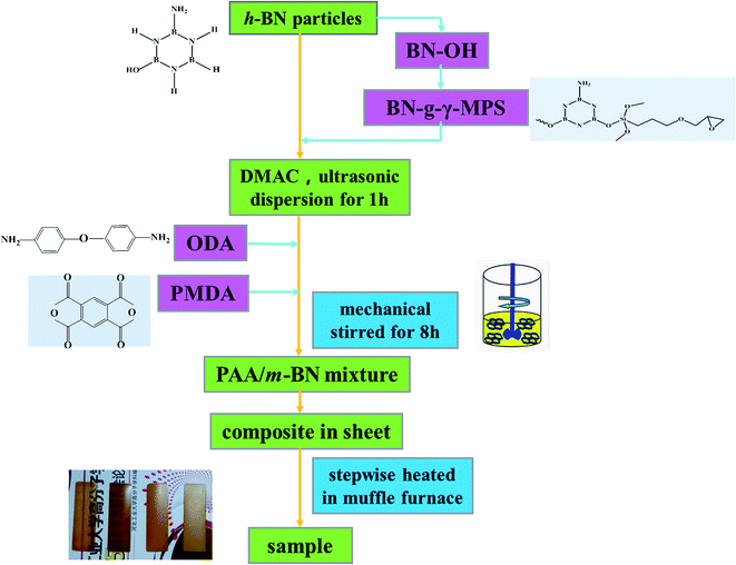
Two-step method was used to prepare PI/m-BN composites with different m-BN contents. The synthesized procedure is shown in Fig. 1. First of all, a certain amount of m-BN (0, 1, 3, 5, 8, 10, 20, 30 and 40% on the weight ratio of PI matrix) was charged in 20 ml DMAc with ultrasonic dispersion at 250 W for 1 h. Then 1.2 g (6 mmol) ODA was added into a 100 ml three-necked round-bottom flask equipped with a mechanical stirrer, and the dispersion was stirred at room temperature under N2 until ODA was thoroughly dissolved. 1.307 g (6 mmol) PMDA was added into the above dispersion every 0.5 h for three times, and then stirred for 8 h at room temperature to form a homogeneous viscous composite precursor, polyamic acid/m-BN (PAA/m-BN) pulp. Finally, the pulp was cast on a glass plate by a doctor's knife and placed in a vacuum oven at 60 °C for 7 h to remove the solvent. The second step was thermally imidization process. The film was further thermally treated in muffle furnace by stepwise heating, from room temperature to 100, 150, 200, 250 °C, and 300 °C, each temperature maintaining for 60 min to convert the PAA to PI completely. The PI/m-BN composite films were cooled to room temperature and peeled off from glass surface by immersing in distilled water. The thickness of the film was controlled about 100 μm. In addition, the reference composites with the addition of untreated BN (h-BN) were also synthesized and denoted as PI/h-BN.Characterization
Fourier-transform infrared (FT-IR) spectroscopy was conducted with a Bruker Vector-22 instrument ranging from 4000 to 400 cm−1. Thermal gravimetric analyses (TGA) were performed with a SDT Q600 (TA Instruments, USA) from 25 to 800 °C at a heating rate of 10 °C under the nitrogen atmosphere. The X-ray diffraction (XRD) analysis was carried out on a Smart Lab X-ray diffraction spectrometer equipped with Cu Ka radiation at a 2θ angle of 10–80° as well as at an operating voltage of 40 kV and a current of 30 mA. Transmission electron microscopy (TEM, Leica EM, Germany) was used to observe the morphology for h-BN and m-BN particles. The wettability characteristics of BN particles were performed on a Kruss tensiometer (DAS30, Germany). Dynamic mechanical analyzer (DMA) was performed on a DMA Q800 (TA Instruments, USA) in a tensile mode under N2. Samples were measured from room temperature to 450 °C at a heating rate of 10 °C min−1 and a frequency of 1 Hz. The morphology and dispersion of m-BN particles in the PI matrix were investigated by a field emission scanning electron microscopy (FE-SEM, Nova Nano SEM 450, FEI). The fractured surfaces of composites were sputtered with a layer of gold before scanning to avoid charge accumulation. Thermal conductivity of PI/h-BN composite was measured by TC 3000 Series Thermal Conductivity Apparatus (Xi'an Xiaxi Co. Ltd., China) based on the transient hot-wire technique at room temperature. Each sample was tested five times to insure accuracy of the measurement, and thermal conductivity (λ, W m−1 K−1) was calculated by the following equation:where, q is the heat generation conducted by per unit per unit length of the wire, ΔT is the temperature changes of the wire and t is the measuring time.25 The ultrahigh electric resistor (ZC36, Shanghai Sixth Electric Meter Factory, China) was used to measure volume and surface resistivity of PI/m-BN composites at room temperature.
Result and discussion
Modification on the surfaces of h-BN particles
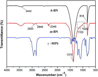
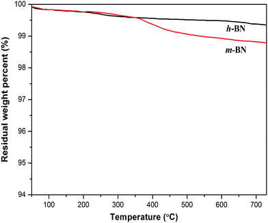
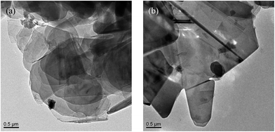
It is important for the composites to enhance the dispersion and interface action between the inorganic filler particles and the polymer matrix. Samples mixing untreated h-BN particles with PI matrix may result in agglomeration of h-BN particles, which will influence the thermal transport performance of the composites. In order to improve the compatibility between the PI and the h-BN particles, 3-glycidyloxypropyltrimethoxy silane (γ-MPS) was used as a surface modifier to functionalize the surface of h-BN particles. The FTIR spectra of h-BN and γ-MPS-modified h-BN (m-BN) are shown in Fig. 2. In the curve of h-BN particles, the broad absorption peak around 1375 cm−1 was owing to the in-plane stretching vibration of h-BN, and the peak at 818 cm−1 was related to out-of-plane bending absorption of the B–N–B. The broad absorption band at 3442 cm−1 was originated from amino group or hydroxyl group (–OH) stretching at the edge planes on the h-BN surface, which was the reactive group from the coupling agent. The new peaks near 2920 cm−1 and 2846 cm−1 were attributed to asymmetric and symmetric –CH2– stretching vibrations from γ-MPS. The peaks appear at 1103 cm−1 and 1020 cm−1 were a fingerprint of the presence of Si–O bonds, which resulted from the reaction between the hydroxylated h-BN and the silane surfactant. These changes of characteristic peaks confirmed that the silane coupling agent, γ-MPS, had been successfully grafted onto the surfaces of h-BN particles.Thermal gravimetric analysis (TGA) was further used to illustrate the successful modification on h-BN particles' surfaces. Fig. 3 shows the TGA curves of h-BN and m-BN. Raw h-BN and m-BN both showed some differences in weight loss with the temperature. Compared with raw h-BN particles, the m-BN had a relatively large weight loss at temperatures around 350–450 °C, which was attributed to the decomposition of the silane molecules. The TGA results were in consistent with that of FTIR, i.e. the silane coupling agent, γ-MPS, had been chemically grafted on the surface of h-BN particles as the m-BN sample was extracted with boiling toluene for two days before analyzing. While the weight grafting ratios is relatively low, the possible reason may be that the morphology of h-BN is similar to graphite, the 001 basal plane is very smooth and has no surface functional groups available for chemical bonding or interaction. Only the edge planes of the lamellar structure have a small quantity of functional groups such as amino groups or hydroxyl groups.26 This result is further proved by TEM images of the h-BN and m-BN particles, as shown in Fig. 4. It can be seen that the 001 basal plane of h-BN is very smooth and almost no uneven edges (Fig. 4(a)), while they becomes rough on the surface of m-BN after the modification (Fig. 4(b)).
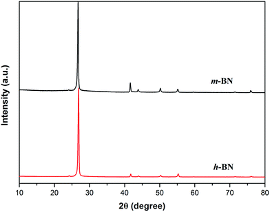
XRD technique is a method to characterize the crystallite size and three-dimensional order of materials. XRD patterns of h-BN and m-BN are shown in Fig. 5. Apparently, the crystal structure of h-BN particles did not change after the surface modification because there was no new peaks appeared. For raw h-BN, the peaks at around 2θ = 26.9° and 41.7° were attributed to the diffraction of (002) and (100) planes of h-BN, respectively. The thickness of c axis direction (Lc) of h-BN can be calculated from the (002) peak using Scherrer's equation, as follows:
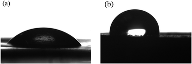
Meanwhile, the surface wettability properties of raw and modified BN were investigated by water contact angle measurement. Related contact angle images are shown in Fig. 6. Raw h-BN belongs to a polar filler, stronger hydrophilic with a contact angle of 53.5° (Fig. 6(a)). After the surfaces were modified with a silane coupling agent (γ-MPS), the contact angle increased to 99.3° (Fig. 6(b)) because of the introduction of alkyl groups, that was, improved the hydrophobic property and promoted the dispersity of m-BN particles in PI matrix.
Thermal conductivity of the PI/m-BN composites
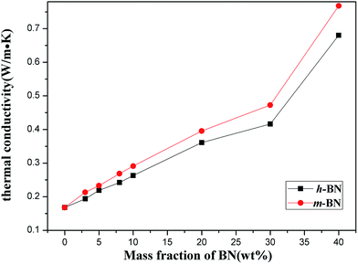
The thermal conductivity of PI/m-BN composites with different weight ratios was measured by the transient hot-wire method at room temperature. Fig. 7 presents the results of the PI/BN composites with h-BN and m-BN particles. It can be seen that the thermal conductivity of the composites increased with the addition of BN. The pure PI had a relatively low thermal conductivity of 0.168 W m−1 K−1. When the loading level of m-BN particles increased to 40 wt%, a significant enhancement of the thermal conductivity could be seen, 0.748 W m−1 K−1, 4.5 times higher than that of pure PI. Two factors are responsible for increasing the thermal conductivity of PI/m-BN composites. One is the filler content. For the composites with relatively low BN loading, there is no direct contact with each other between BN particles. This is due to the BN particles isolated and wrapped dispersion in PI matrix, which leads to the interface thermal resistance between h-BN particles becoming very large. Therefore, the values of thermal conductivity of composites filled with low BN contents are low. With increasing of the BN content, the BN particles could contact with each other to form continuous chains of particles over the whole samples and form thermally conductive pathways or thermal percolating network. The thermal conductivity of PI/m-BN composites is improved further after the modification of h-BN surface which results from the higher interface compatibility between m-BN particles and PI matrix. In theory, the thermal conductive pathways are formed by the interface of the composites through phonon boundary scattering.28 The silane coupling agent acts as phonon transfer bridges between m-BN particles and the PI matrix. One end is linked with the surface of the m-BN fillers and the other of the carboxyl group reacts with the end of PAA main chain. The surface chemistry modification could promote m-BN particles dispersing well in the PI matrix, and reduce the interfacial thermal resistance caused by phonon scattering. The strong covalent bonds between the m-BN particles and PI matrix improve interfacial compatibility. Fig. 8 shows the fractured surfaces of the composites with different m-BN contents by SEM observation. Fig. 8(a) shows that fractured surface of pure PI is very smooth. When the content of m-BN particles is 5 wt% (Fig. 8(b)), m-BN particles are separated from each other and disperse uniformly in the PI matrix. While the content of m-BN particles increases to 20 wt% and 40 wt% (Fig. 8(c and d)), the particles contact each other and form conductive pathways in composites, resulting in high thermal conductivity of the composites.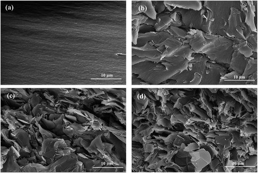 | ||
| Fig. 8 SEM images of the fractured surface of samples: (a) pure PI, and PI/m-BN composites with different m-BN contents, (b) 5 wt%, (c) 20 wt%, (d) 40 wt%. | ||
Thermal stability of the PI/m-BN composites
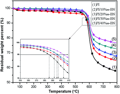
Thermal stability is one of the important properties for the composites in processing and application. Addition of fillers into a polymer matrix may bring some changes in the thermal characteristics of the resulting composites. Fig. 9 shows the TGA curves for PI/m-BN composites with different m-BN contents. The temperatures at 10 wt% mass loss and the maximum degradation rate are listed in Table 1. It can be seen that pure PI exhibited high thermal stability, and the temperatures for 10% weight loss (T10%) and maximum degradation rate temperature (Tmax) appeared at 585.5 °C and 598.7 °C, respectively. This is attributed to the existence of benzene rings and imide rings of polyimide. While the T10% values of the PI/m-BN composites increased with increasing of the m-BN content, and the Tmax values of composites were all higher than that of pure PI. This is due to that m-BN particles possess high heat capacity and thermal conductivity and can form heat resisting layers acting as mass transport barriers, which will delay the escape of volatile degradation.29 As a result, the m-BN particles leads to the enhanced thermal stability of the PI/m-BN composites.| Sample | TGA | DMA | FTIR | |||
|---|---|---|---|---|---|---|
| T10% (°C) | Tmax (°C) | Tg (°C) | tan![[thin space (1/6-em)]](https://www.rsc.org/images/entities/char_2009.gif) δ δ |
E′ | I1371/I1497 | |
| PI/0% m-BN | 585.5 | 598.7 | 417.5 | 0.3212 | 1710 | 0.77 |
| PI/10% m-BN | 592.0 | 603.7 | 412.2 | 0.2569 | 1982 | 0.74 |
| PI/20% m-BN | 595.2 | 601.1 | 409.6 | 0.2481 | 2503 | 0.67 |
| PI/30% m-BN | 596.5 | 600.9 | 408.9 | 0.2144 | 4215 | 0.66 |
| PI/40% m-BN | 603.4 | 605.1 | 404.4 | 0.1947 | 4573 | 0.55 |
Electrical insulation property of the PI/m-BN composites
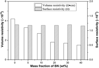
The electrical insulation property is important for thermally conductive packaging materials, which are used in the fields of electron and electrical appliance. High electrical insulation is a key factor to ensure safety and stability work of the electronic components. Surface resistivity and volume resistivity are two of the crucial parameters that characterize the electrical insulation property. Fig. 10 shows the electrical insulation property of PI/m-BN composites for different m-BN contents. The results suggested that the volume resistivity of pure PI was about 4.2 × 10¹⁷ Ω, and the volume resistivity of composites decreased slightly with m-BN introduction, while still maintained the same order of magnitude as the pure PI. Meanwhile the surface resistivity displays no change. The composites still possess excellent electrical insulation property. Therefore, the PI/m-BN composites kept high thermal conductivity with fine electrical insulation properties, and are appropriate for the application as packaging materials.Dynamic mechanical analysis of the PI/m-BN composites
Dynamic mechanical analysis (DMA) is a useful technique to obtain the characteristic parameters of the materials in the structure, process and application. For inorganic fillers filled polymer composites, the viscoelasticity not only reflects the every component's molecular relaxation but also reveals the morphology, the interactions among each component and other factors of the composites.30 The storage moduli (E′) as a function of temperature for PI/m-BN composites are plotted in Fig. 11(a). It is clearly observed that the storage moduli of the composites are obviously higher than that of the pure PI within the experimental temperature range, and the PI composite filled with a larger content of m-BN particles has a higher storage modulus value. For example, the storage moduli of the PI/m-BN composites with 0%, 10%, 20%, 30% and 40 wt% m-BN contents at 150 °C were 1710, 1982, 2503, 4215 and 4573 MPa, respectively. This phenomenon can be explained in terms of the addition of the m-BN fillers. The m-BN particles possess inherent high modulus and their large diameter-thickness ratio makes the existence of bigger interfacial interaction between the m-BN particles and PI matrix. This leads to the applied stress transferred from the PI to m-BN fillers. When the temperature is above 380 °C, the storage modulus decreased significantly, this is because that the molecular chains need to dissipate energy in order to overcome viscous motion.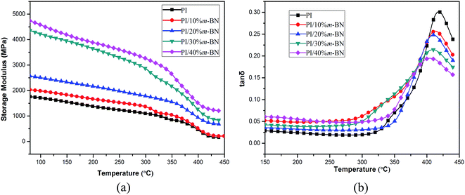 | ||
| Fig. 11 Storage modulus (a) and loss tangent (b) versus temperature for PI/m-BN composites with different m-BN contents. | ||
The loss tangent (tan![[thin space (1/6-em)]](https://www.rsc.org/images/entities/char_2009.gif) δ) is the ratio of loss modulus to the storage modulus. The width and height of tan
δ) is the ratio of loss modulus to the storage modulus. The width and height of tan![[thin space (1/6-em)]](https://www.rsc.org/images/entities/char_2009.gif) δ peak are important for measuring the damping behavior of materials. The temperature of the tan
δ peak are important for measuring the damping behavior of materials. The temperature of the tan![[thin space (1/6-em)]](https://www.rsc.org/images/entities/char_2009.gif) δ maximum peak is regarded as the glass transition temperature (Tg). Fig. 11(b) shows the variation of tan
δ maximum peak is regarded as the glass transition temperature (Tg). Fig. 11(b) shows the variation of tan![[thin space (1/6-em)]](https://www.rsc.org/images/entities/char_2009.gif) δ as a function of temperature for PI/m-BN composites. It is interesting to note that the Tg values of the composites shifted to lower temperatures with the addition of m-BN particles. The Tg values of PI/m-BN composites with 0%, 10%, 20%, 30%, 40 wt% m-BN contents are 417.5, 412.2, 409.6, 408.9, 404.4 °C, respectively, as listed in Table 1. Nevertheless, for polyimide composites, some researchers reported an increase in the Tg as a function of filler content,21,31 however, decreases in the Tg have rarely been reported. What result in the Tg decrease? Firstly, the addition of rigid m-BN particles occupy a certain part of volume, and the molecular chain accumulation intensity decreases, leading to the motion of polymer chain segments much easier. The weak chain–chain interaction results in a lower Tg value.8 Secondly, the imidization degree of polyimide would reduce with the introduction of m-BN particles, leading to the decrease of Tg. Because PI with a higher degree of imidization has stiff molecular chains and thus reduces molecular motion ability, on the contrary, the molecular chains of PI/m-BN composites with a lower degree of imidization show higher flexible.32 This is described in more detail below. Thirdly, the h-BN particles were functionalization by silane coupling agent, a number of flexible silane chain-segments formed on the BN surface increased the molecular chains segmental mobility of PI, and thus led to a reduction in Tg of PI/m-BN composites.33 The height of the tan
δ as a function of temperature for PI/m-BN composites. It is interesting to note that the Tg values of the composites shifted to lower temperatures with the addition of m-BN particles. The Tg values of PI/m-BN composites with 0%, 10%, 20%, 30%, 40 wt% m-BN contents are 417.5, 412.2, 409.6, 408.9, 404.4 °C, respectively, as listed in Table 1. Nevertheless, for polyimide composites, some researchers reported an increase in the Tg as a function of filler content,21,31 however, decreases in the Tg have rarely been reported. What result in the Tg decrease? Firstly, the addition of rigid m-BN particles occupy a certain part of volume, and the molecular chain accumulation intensity decreases, leading to the motion of polymer chain segments much easier. The weak chain–chain interaction results in a lower Tg value.8 Secondly, the imidization degree of polyimide would reduce with the introduction of m-BN particles, leading to the decrease of Tg. Because PI with a higher degree of imidization has stiff molecular chains and thus reduces molecular motion ability, on the contrary, the molecular chains of PI/m-BN composites with a lower degree of imidization show higher flexible.32 This is described in more detail below. Thirdly, the h-BN particles were functionalization by silane coupling agent, a number of flexible silane chain-segments formed on the BN surface increased the molecular chains segmental mobility of PI, and thus led to a reduction in Tg of PI/m-BN composites.33 The height of the tan![[thin space (1/6-em)]](https://www.rsc.org/images/entities/char_2009.gif) δ peak gradually decreased with increasing m-BN particles, indicating the rigidity of composites increased. This is related to the strong interfacial interaction between m-BN particles and PI matrix.
δ peak gradually decreased with increasing m-BN particles, indicating the rigidity of composites increased. This is related to the strong interfacial interaction between m-BN particles and PI matrix.
Effect of the imidization degree on the structure of the PI/m-BN composites
FTIR spectroscopy can effectively evaluate the imidization degree and chemical structure of PI/m-BN composites. In this study, the imidization degree was evaluated by FTIR spectroscopy based on absorbance superposition and Lambert–Beer Law.34 FTIR spectra of the m-BN, PI and PI/m-BN composites are shown in Fig. 12. The absorption peak at 1497 cm−1 related to the C–C stretching of aromatic benzene is designated as an internal standard because it does not change during imidization process. The degree of imidization can be determined by the ratio of the absorbance at 1371 cm−1 (C–N–C) to that of C–C stretching at 1497 cm−1, namely I1371/I1497.35 The values calculated by I1371/I1497 of the PI/m-BN composites with 0%, 10%, 20%, 30%, 40 wt% m-BN contents were 0.77, 0.74, 0.67, 0.66, 0.55, respectively (Table 1). It can be seen that the imidization degree gradually decreased with the increasing of m-BN content. It is likely because the inorganic–organic networks are formed in the composites after the addition of m-BN particles, which result from the stereo-hindrance effect. It will restrict the PAA chain segments convert into PI chain segments. Furthermore, the addition of m-BN particles can result in the molecular weight of PI/m-BN composites lower than that of PI. The small molecules in PI/m-BN composites can absorb energy and transfer it to heat capacity, while PI with high molecular weight may prevent the heat capacity to be lost from its surface.36 So with the m-BN content increasing, the imidization degree of composites decreased, leading to the reduction in Tg of PI/m-BN composites. The peaks at 815 cm−1 and 1370 cm−1 become broader due to m-BN absorption, as shown in Fig. 12.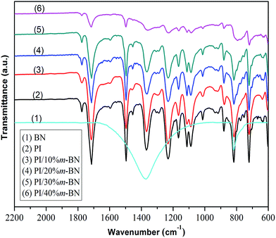 | ||
| Fig. 12 FTIR spectra of (1) m-BN, (2) PI and PI/m-BN composites with different m-BN contents: (3) 10%, (4) 20%, (5) 30%, (6) 40%. | ||
XRD results further illustrated the stability of crystal structure of m-BN. Fig. 13 compares the XRD patterns of PI/m-BN composites. The diffraction peak at around 15° to 19° indicates the amorphous structure of PI molecules, and the diffraction peak intensity become stronger and broader when the m-BN contents increased from 10% to 40%. This showed that the addition of m-BN particles destroyed the orderly arrangement of PI and lowered the packing density of PI molecules. Meanwhile, the patterns of the PI/m-BN composites were similar to that of h-BN, indicating that m-BN particles still remained stable after being added into the PI matrix.37 The XRD peak intensity at 2θ = 26.9° increased with the addition of the higher m-BN mass fractions, while the d-spacing of the layer distance of m-BN in the PI/m-BN composites show slight change which might be due to the BN aggregates in the PI matrix.38
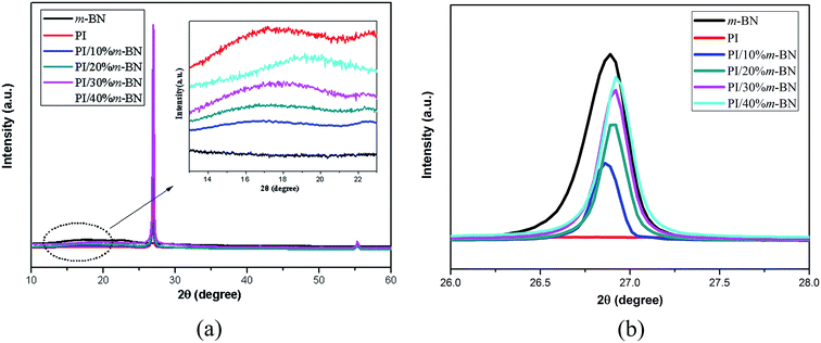 | ||
| Fig. 13 XRD patterns of (a) pure PI, m-BN and PI/m-BN composites with different m-BN contents, (b) enlarge (a) of the 2θ ranging from 26° to 28°. | ||
Conclusions
PI/m-BN composites were successfully prepared via in situ polymerization. The silane coupling agent, namely, 3-glycidyloxypropyltrimethoxy silane (γ-MPS), was used to modify raw h-BN, and acted as a bridge between m-BN particles and PI matrix. FTIR analysis, contact angle test and TEM observation demonstrated that the silane coupling agent was chemically grafted on the surfaces of h-BN particles. This improved dispersion of m-BN particles in PI matrix and increased the thermal conductivity of PI/m-BN composites. When the loading level of m-BN reached 40%, the thermal conductivity of 0.768 W m−1 K−1 was obtained, which was 4.6 times higher than that of pure polyimide. Meanwhile, the SEM observation showed that m-BN particles uniformly dispersed in PI matrix, and particles contacted with each other to form a continuous thermal conductive network, contributing to the enhancement of thermal conductivity of the composites. In addition, the thermal stability, storage modulus was higher than that of pure PI except to the decrease of Tg value with the addition of m-BN into PI matrix. Besides, the PI/m-BN composites maintained excellent electrical insulation property, which has promising applications in microelectronic industry as future substrate materials requiring effective heat dissipation.Acknowledgements
This work was financially supported by National Natural Science Foundation (contact no. 51573037), Program for Changjiang Scholars and Innovative Research Team in University (IRT13060) and Key Lab for Micro- and Nano-Scale Boron Nitride Materials in Hebei Province.References
- Y. M. Chen and J. M. Ting, Carbon, 2002, 40, 359 CrossRef CAS.
- L. L. Qin, G. H. Li and J. Hou, Polym. Compos., 2015, 36, 1675 CrossRef CAS.
- M. Hu, D. Yu and J. Wei, Polym. Test., 2007, 26, 333 CrossRef CAS.
- C. L. Choy, Y. W. Wong and G. W. Yang, J. Polym. Sci., Part B: Polym. Phys., 1999, 37, 3359 CrossRef CAS.
- M. Akatsuka and Y. Takezawa, J. Appl. Polym. Sci., 2003, 89, 2464 CrossRef CAS.
- J. Che, T. Çağın and W. Deng, J. Phys. Chem. A, 2000, 113, 6888 CrossRef CAS.
- S. Ghosh, W. Bao, D. L. Nika and S. Subrina, Nat. Mater., 2010, 9, 555 CrossRef CAS PubMed.
- M. H. Tsai, I. H. Tseng, J. C. Chiang and J. J. Li, ACS Appl. Mater. Interfaces, 2014, 6, 8639 CAS.
- Z. Han and A. Fina, Prog. Polym. Sci., 2011, 36, 914 CrossRef CAS.
- Y. P. Mamunya, V. V. Davydenko, P. Pissis and E. V. Lebedev, Eur. Polym. J., 2002, 38, 1887 CrossRef CAS.
- J. Hou, G. H. Li and N. Yang, RSC Adv., 2014, 4, 44282 RSC.
- S. Kume, I. Yamada and K. Watari, J. Am. Ceram. Soc., 2009, 92, S153 CrossRef CAS.
- L. Fang, C. Wu and R. Qian, RSC Adv., 2014, 4, 21010 RSC.
- Y. Liao, X. Wu and H. Liu, Thermochim. Acta, 2011, 526, 178 CrossRef CAS.
- K. Wattanakul, H. Manuspiya and N. Yanumet, J. Appl. Polym. Sci., 2011, 119, 3234 CrossRef CAS.
- E. Çakmakçı, C. Koçyiğit, S. Cakır and A. Durmus, Polym. Compos., 2014, 35, 530 CrossRef.
- W. Jin, W. Zhang and Y. Gao, Appl. Surf. Sci., 2013, 270, 561 CrossRef CAS.
- J. Yu, X. Huang and C. Wu, Polymer, 2012, 53, 471 CrossRef CAS.
- H. L. Lee, O. H. Kwon and S. M. Ha, Phys. Chem. Chem. Phys., 2014, 16, 20041 RSC.
- D. H. Kuo, C. Y. Lin, Y. C. Jhou, J. Y. Cheng and G. S. Liou, Polym. Compos., 2013, 34, 252 CrossRef CAS.
- T. L. Li and S. L. C. Hsu, J. Phys. Chem. B, 2010, 114, 6825 CrossRef CAS PubMed.
- S. Diaham, F. Saysouk, M. L. Locatelli and B. Belkerk, J. Appl. Polym. Sci., 2015, 132, 42461 CrossRef.
- S. Diaham, F. Saysouk, M. L. Locatelli and T. Lebey, J. Phys. D: Appl. Phys., 2015, 48, 385301 CrossRef.
- R. Qian, J. Yu and L. Xie, Polym. Adv. Technol., 2013, 24, 348 CrossRef CAS.
- W. Yu and S. U. S. Choi, Rev. Sci. Instrum., 2006, 77, 76102 CrossRef.
- K. Sato and H. Horibe, J. Mater. Chem., 2010, 20, 2749 RSC.
- X. B. Huan, W. Wei and X. L. Zhao, Chem. Commun., 2010, 46, 8848 RSC.
- S. Y. Yang, C. C. M. Ma, C. C. Teng and Y. W. Huang, Carbon, 2010, 48, 592 CrossRef CAS.
- Y. S. Ye, Y. C. Yen, C. C. Cheng and Y. J. Syu, Polymer, 2010, 51, 430 CrossRef CAS.
- G. D. Smith, D. Bedrov and L. Li, J. Phys. Chem. A, 2002, 117, 9478 CrossRef CAS.
- F. X. Qiu, Y. M. Zhou and J. Z. Liu, Eur. Polym. J., 2004, 40, 713 CrossRef CAS.
- M. B. Saeed and M. S. Zhan, Eur. Polym. J., 2006, 42, 1844 CrossRef CAS.
- H. C. Wu and M. R. Kessler, ACS Appl. Mater. Interfaces, 2015, 7, 5915 CAS.
- Y. K. Xu, M. S. Zhan and K. Wang, J. Polym. Sci., Part B: Polym. Phys., 2004, 42, 2490 CrossRef CAS.
- W. S. Li, Z. X. Shen, J. Z. Zheng and S. H. Tang, Appl. Spectrosc., 1998, 52, 985 CrossRef CAS.
- Y. H. Lu and M. S. Zhan, J. Polym. Sci., Part B: Polym. Phys., 2005, 43, 3621 CrossRef CAS.
- S. K. Kisku and S. K. Swain, J. Am. Ceram. Soc., 2012, 95, 2753 CrossRef CAS.
- A. Alias, Z. Ahmad and A. B. Ismail, Mater. Sci. Eng., R, 2011, 176, 799 CrossRef CAS.
| This journal is © The Royal Society of Chemistry 2016 |

