Selective electro-reforming of waste polyethylene terephthalate-derived ethylene glycol into C2 chemicals with long-term stability†
Yuxiang
Wang
ab,
Kesheng
Liu
ab,
Fulai
Liu
a,
Chuxuan
Liu
ab,
Rui
Shi
 *a and
Yong
Chen
 *ab
*ab
aKey Laboratory of Photochemical Conversion and Optoelectronic Materials & CAS-HKU Joint Laboratory on New Materials, Technical Institute of Physics and Chemistry, Chinese Academy of Sciences, Beijing 100190, People's Republic of China. E-mail: shirui@mail.ipc.ac.cn; chenyong@mail.ipc.ac.cn
bUniversity of Chinese Academy of Sciences, Beijing 100049, People's Republic of China
First published on 13th July 2023
Abstract
Electro-oxidation of ethylene glycol (EG) derived from polyethylene terephthalate (PET) into value-added C2 products is essential for the electro-reforming of waste PET. However, achieving high selectivity and stability in the EG oxidation reaction (EGOR) remains a significant challenge. Herein, we successfully fabricated segregation-less Pd1Ag1 alloy nanoparticles (NPs) that can be used for the electro-reforming of waste PET into glycolate C2 products with high selectivity (97%) and long-term stability (>500 h). Electrochemical measurements and in situ Fourier-transform infrared spectroscopy (FTIR) results reveal that the addition of Ag atoms improves glycolate selectivity by reducing its adsorption on Pd active sites. In addition, the surface *OH species generated on Ag sites facilitate the rapid oxidation of toxic carbonyl species, thereby improving the stability of Pd sites. Therefore, the synergistic effects of Pd1Ag1 NPs provide an effective way for practical electro-reforming of real-world waste PET into value-added products with high selectivity and stability.
Accumulation of plastic waste has led to severe environmental concerns,1,2 and there is an urgent need to develop effective methods for recycling end-of-life plastics. PET is a widely used polyester plastic,3,4 and various physical and chemical recycling methods have been developed to recycle PET. Currently, approximately 90% of recycled PET is reclaimed through traditional mechanical recycling, but this approach often results in inferior properties of the reproduced materials compared to those of raw PET.5 In contrast, chemical recycling methods involve the degradation of PET into monomers through hydrolysis,6 methanolysis7 and glycolysis,8 followed by repolymerisation to produce PET, which can enable closed-loop recovery. However, these methods are cost-ineffective.9
Recently, chemical recycling of PET through electro-reforming has received increasing attention.10–13 The electro-oxidation of PET-derived ethylene glycol (EG) into value-added products that can be easily separated is a crucial step in this process. Several groups have reported the electro-reforming of PET-derived EG into C1 products, such as carbonate and formate.10–17 Compared to the deep oxidation to generate C1 products, the controllable oxidation of EG into specific high-value C2 products is more meaningful and also cost-effective. For instance, glycolic acid (GA) is an important industrial raw material that can be used as a monomer for the synthesis of biodegradable plastic polyglycolic acid.18 However, the selective conversion of EG into GA is still challenging due to issues such as (i) the strong adsorption of intermediates on the Pd active sites, which reduces the selectivity of glycolate,19 and (ii) the rapid deactivation of Pd-based catalysts during the electro-catalytic oxidation of alcohols caused by carbonyl species poisoning.20–23 Researchers have attempted to address these challenges. For example, recent works have reported that Au or Pd nanoparticles loaded on Ni(OH)2 substrates can convert PET into glycolate.24,25 Shi and co-workers achieved the production of value-added GA by using PdAg/NF as the anode electro-catalyst.26 However, the performance of the catalyst is still far from satisfactory. The rapid deactivation of the catalyst makes it unavailable for practical scenarios.
Herein, we report highly alloyed Pd1Ag1 nanoparticles (NPs) as an efficient electrocatalyst for upcycling PET-derived EG into glycolate. The use of a strong reducing agent is crucial for fabricating a nanoparticle alloy, which exposes more surface Ag sites by avoiding segregation. Specifically, the addition of Ag atoms improves the selectivity and stability of Pd-based catalysts in the EGOR process by optimising the electronic structure and surface species. On the one hand, Ag atoms reduce the adsorption energy of glycolate on Pd sites, thus preventing unwanted over-oxidation and achieving high glycolate selectivity. On the other hand, Ag atom sites induce a large amount of *OH active species to facilitate rapid oxidation of carbonyl species at the Pd active sites because of their high affinity with water,27,28 and hence, this alleviates catalyst poisoning. Our results show that Pd1Ag1 NPs demonstrate efficient electro-reforming of EG into glycolate with a high selectivity of 97% at 0.75 V vs. RHE. The electro-catalytic activity remains stable for over 500 h without attenuation. In a real two-electrode flow cell, the selectivity of glycolate is 91% when 52% of PET-derived EG is electro-reformed.
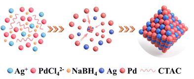
PdxAgy NPs were synthesised via the simultaneous reduction of H2PdCl4 and AgNO3 with ascorbic acid in CTAC aqueous solution at room temperature, as depicted in Scheme 1. The face-centred crystal structure of the resulting PdxAgy NPs was confirmed by X-ray diffraction (XRD). As shown in Fig. 1a, the diffraction peaks of PdxAgy nanoparticles were located between the peaks of pure Pd (PDF#46-1043) and pure Ag (PDF#89-3722). The diffraction peaks of PdxAgy NPs shifted from Pd to Ag as the Pd/Ag ratio decreased, indicating the formation of a Pd–Ag alloy structure rather than phase separation. X-ray photoelectron spectroscopy (XPS) was used to investigate the chemical environments of Pd and Ag (Fig. 1b and c). The binding energy of Pd 3d and Ag 3d in Pd1Ag1 NPs shifted negatively compared to Pd and Ag binding energies, which is attributed to the electron transfer from Ag to Pd. These shifts are consistent with previous reports.29–32 The Ag 3d5/2 peak shift of Pd–Ag NPs prepared with NaBH4 was more negative than that prepared with ascorbic acid (Fig. S1a†). This stronger electron transfer implies an increase in the Ag–Pd coordination number, i.e., a higher dispersion.33 Furthermore, to study the influence of Pd–Ag interaction on the electronic structure, the d-band centres of Pd/C and Pd1Ag1 NPs were evaluated using surface valence band photoemission spectra. Pd1Ag1 NPs showed an obvious negative shift compared with Pd/C (−4.72 eV vs. −4.21 eV) (Fig. S1b†).34 Such a downshift of the d-band centre implies a relatively weak adsorption of the reaction intermediate on Pd sites,32,35–37 which is beneficial for the selective conversion of EG into C2 products. The actual Pd/Ag molar ratio of the samples was quantified using inductively coupled plasma optical emission spectrometry (ICP-OES) (Table S1†). The calculated molar ratio of Pd to Ag is essentially the same as the stoichiometry in the synthesis. Scanning electron microscopy (SEM) images showed that the Pd1Ag1 alloy NPs had an average size of 20 nm (Fig. 1d). High-resolution transmission electron microscopy (HRTEM) examination revealed that the lattice fringes of Pd1Ag1 NPs exhibited interplanar spacings of 0.233 and 0.196 nm in the particle, corresponding to the (111) and (200) planes of the face-centred cubic Pd1Ag1 alloy (Fig. 1e). No defects and lattice changes were observed in the clear lattice images, indicating that segregation was prevented. Energy-dispersive X-ray elemental maps confirmed that Pd and Ag elements were evenly distributed throughout the Pd1Ag1 NP structure (Fig. 1f). Collectively, these results indicate the successful synthesis of a Pd–Ag NP alloy structure.
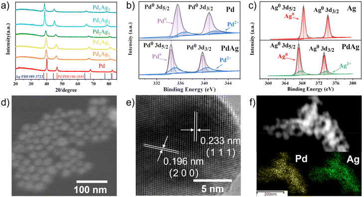 | ||
| Fig. 1 (a) XRD patterns of PdxAgy NPs. High-resolution XPS spectra of (b) Pd 3d and (c) Ag 3d. (d) SEM, (e) HRTEM and (f) mapping images of Pd1Ag1 NPs. | ||
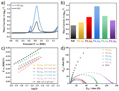
Prior to the electro-reforming process, PET was hydrolysed into terephthalate (TPA) and EG in an alkaline solution. As TPA precipitates in strong alkaline solutions, the electro-oxidation of EG was examined as a model reaction via a simple three-electrode system. The electrochemically active surface area (ECSA) of PdxAgy NPs and commercial Pd/C was evaluated through the reduction process of Pd oxides, and the results are presented in Table S1.† The ECSA of PdxAgy NPs was found to be slightly less than that of commercial Pd/C. To investigate the catalytic ability of PdxAgy NPs and commercial Pd/C toward EG oxidation, cyclic voltammetry (CV) curves were recorded in 1 M KOH and 1 M EG. The electro-catalytic current was normalised with respect to the mass of Pd (Fig. 2a) since the EGOR activity of Ag is negligible in this potential range (Fig. S2†). The pronounced anodic peaks in the forward and backward sweeps at 0.85 V and 0.65 V vs. RHE were attributed to oxidation of EG and other intermediate species, respectively. The current density of different compositions normalized with the carbon glass area and ECSA showed similar peaks (Fig. S3†). The Pd/Ag ratio of 1![[thin space (1/6-em)]](https://www.rsc.org/images/entities/char_2009.gif) :
:![[thin space (1/6-em)]](https://www.rsc.org/images/entities/char_2009.gif) 1 exhibited the best EGOR performance (Fig. 2b), with the highest peak current of 1.36 A mgPd−1, which was substantially larger than that of Pd/C (0.55 A mgPd−1). Despite the smaller ECSA of Pd1Ag1 NPs compared to commercial Pd/C, they exhibited higher intrinsic catalytic activity than Pd/C (Fig. S3†). To better understand the reason for this high activity, the Tafel slope and electrochemical impedance spectra were measured. The lower Tafel slope of Pd1Ag1 NPs (118.5 mV dec−1) than that of commercial Pd/C (153.5 mV dec−1) illustrates efficient catalytic performance (Fig. 2c). Meanwhile, the Pd1Ag1 NPs present a smaller charge transfer resistance (Rct) than commercial Pd/C, which is also favourable for interfacial electron transfer kinetics during EGOR (Fig. 2d).
1 exhibited the best EGOR performance (Fig. 2b), with the highest peak current of 1.36 A mgPd−1, which was substantially larger than that of Pd/C (0.55 A mgPd−1). Despite the smaller ECSA of Pd1Ag1 NPs compared to commercial Pd/C, they exhibited higher intrinsic catalytic activity than Pd/C (Fig. S3†). To better understand the reason for this high activity, the Tafel slope and electrochemical impedance spectra were measured. The lower Tafel slope of Pd1Ag1 NPs (118.5 mV dec−1) than that of commercial Pd/C (153.5 mV dec−1) illustrates efficient catalytic performance (Fig. 2c). Meanwhile, the Pd1Ag1 NPs present a smaller charge transfer resistance (Rct) than commercial Pd/C, which is also favourable for interfacial electron transfer kinetics during EGOR (Fig. 2d).
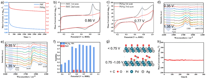
Poor stability is a major challenge in the electro-reforming of PET. To assess the stability of the catalysts, chronoamperometry (CA) measurements were conducted in a mixture of 1 M KOH and 1 M EG for 3600 s. As shown in Fig. 3a, the current densities of both catalysts decreased rapidly at the beginning of the stability test, mainly because of the adsorption and accumulation of Pd oxides on the active site surface.38 The Pd1Ag1 NPs retained 83% of their initial mass activity after 3600 s at 0.85 V vs. RHE, which is considerably better than that of commercial Pd/C. Moreover, a comparison of the performance of other catalysts with that of the proposed catalysts is presented in Table S2;† the results show that the stability of Pd1Ag1 NPs in the EGOR process is superior to that of all reported Pd-based alloy catalysts in the literature. To investigate the origin of this improved stability, CO anti-poisoning experiments were conducted (Fig. 3b and c). Compared to commercial Pd/C, the anodic wave belonging to the electro-oxidation of adsorbed CO into CO2 on the Pd1Ag1 NP surface shifted to a lower potential, indicating that carbonyl species were more easily oxidised on the Pd1Ag1 NP surface. Furthermore, we conducted electrochemical in situ FTIR measurements, and the corresponding binding assignments are provided in Table S3.† As shown in Fig. 3d, clear signals of carbonyl species can be detected on the Pd/C surface in all potential ranges. However, the characteristic peak of CO on the Pd1Ag1 NP surface was barely detectable (Fig. 3e), indicating that the oxidation of carbonyl species was enhanced within this potential range.
Furthermore, our findings show that the stability of Pd1Ag1 NPs varies significantly in different voltage ranges (Fig. 3f). Specifically, the current density decreased to below 40% after 3600 s of the EGOR process, when the potential was less than 0.75 V. However, it remains above 75% when the potential was within the range of 0.75–1.05 V, with the highest stability (83%) observed at 0.85 V. Conversely, when the voltage exceeded 1.1 V, the catalyst deactivated rapidly (Fig. S4†). To clarify this point, we monitored the formation of *OH species by an electrochemical method to reveal the rapid oxidation mechanism of carbonyl species. As shown in Fig. S5,† *OH species were detected within the 0.75–1.05 V vs. RHE range; additionally, high stability was also observed in this range. These results provide evidence that the production of *OH species was positively correlated with the stability of the catalyst. Specifically, since Ag atoms possess higher affinity with water than EG (Fig. S6†), the *OH species generated at Ag sites provide highly reactive oxygen species for the rapid oxidation of carbonyl species,35 thus preventing the poisoning of the Pd active sites (Fig. 3g). At low potentials (<0.75 V vs. RHE), the generation of adequate *OH on Ag sites was difficult, which leads to the accumulation of carbonyl species on Pd active sites and catalyst poisoning. At a potential of 1.1 V vs. RHE, Ag was oxidised to [Ag(OH)2]−ads, which was adsorbed onto the catalyst surface, resulting in catalyst deactivation.39,40 After comprehending the properties associated with the stability of Pd1Ag1 NPs, a 500 h chronoamperometry experiment was conducted at 0.85 V vs. RHE under fluidic state. The result revealed that 0.1 mg of Pd1Ag1 NPs dispersed on a carbon cloth could maintain a current of 50–60 mA mgPd−1 without attenuation (Fig. 3h). Moreover, TEM and HRTEM images confirm that the morphology of Pd1Ag1 NPs is well maintained after long-term electro-reforming (Fig. S7†).
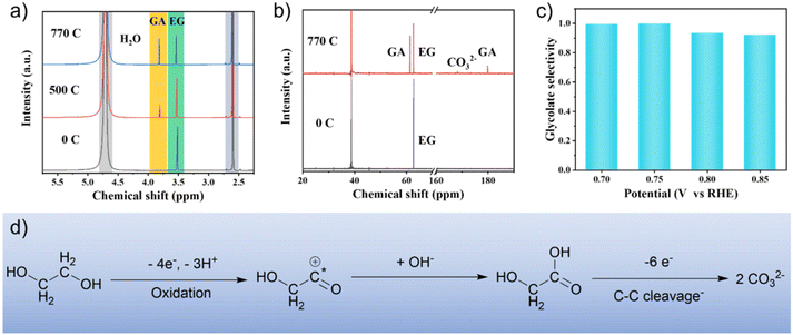
Nuclear magnetic resonance (NMR) spectra were obtained to identify the intermediates and products during EG oxidation. The 1H NMR and 13C NMR spectra (Fig. 4a and b) showed that glycolate is the main product with a selectivity of 97% at 0.75 V vs. RHE. At the same time, the carbonate formed by further oxidation of glycolate can be observed from 13C NMR spectra. In addition, no other by-products (e.g. formate and oxalate) were detected (Fig. S8†). The selectivity of glycolate was also investigated at different voltages. The results show that when the conversion of EG was about 50%, the selectivity of glycolate was more than 90% in the range of 0.7–0.85 V vs. RHE (Fig. 4c and S9†). In situ FTIR spectroscopy was used to investigate the origin of the high selectivity of glycolate (Fig. 3d and e). The blue-shift of the characteristic wavenumber of glycolate in Pd1Ag1 NPs (1415 cm−1) compared to commercial Pd/C (1405 cm−1) indicates a relatively weak adsorption of glycolate,41 which indicates limited deep oxidation and improved selectivity of glycolate.26 Furthermore, this result is supported by the negative shift of the d-band centre in Pd1Ag1 NPs (−4.72 eV) compared with Pd/C (−4.21 eV) (Fig. S1†), suggesting that the addition of Ag atoms can fine-tune the electronic structure to reduce the glycolate adsorption energy and improve glycolate selectivity.
Moreover, in situ FTIR can also reveal the mechanism of the EGOR process. A vibration peak at 1630 cm−1 was detected on the surface of Pd1Ag1 NPs, corresponding to the adsorbed 2-hydroxyethyl intermediate, which further transforms into glycolate (Fig. 3d).42,43 Based on the above results, a plausible pathway for EG oxidation was proposed, as shown in Fig. 4d. Initially, EG undergoes oxidative dehydrogenation at the surface to form adsorbed 2-hydroxyethyl species, which then combine with hydroxyl groups to generate glycolate. Finally, a small amount of glycolate undergoes C–C cleavage to form carbonate.
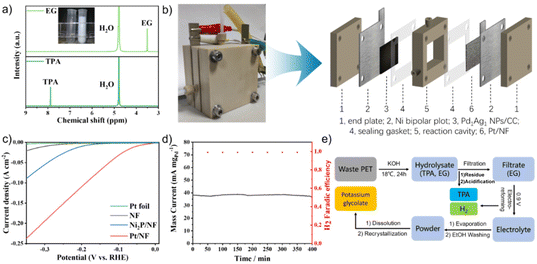
To evaluate the feasibility of electro-reforming of PET, colourless, blue and green plastic bottles were selected as raw materials for hydrolysis. The separated pure EG and TPA were characterised using 1H NMR spectra (Fig. 5a and S10†). TPA with a purity of 99.5% and a yield of 98% was obtained through the acidification of the filter residue of PET hydrolysis products. The Pd1Ag1 NPs were then used as the anode to electrochemically reform the hydrolysate of real-world PET bottles in a flow cell (Fig. 5b). Nickel foam (NF) loaded with Pt NPs (Pt/NF) was chosen as the cathode based on a comparison of the hydrogen evolution reaction (HER) overpotential (Fig. 5c). The current density was stabilised at 40 mA mgPd−1 during 400 min of continuous electrolysis at a cell voltage of 0.9 V (Fig. 5d). The 1H NMR spectra revealed that the conversion rate of EG was 52% and the selectivity of glycolate was 91% (Fig. S11†).
To purify glycolate, the powder collected by evaporating the electrolyte was cleaned with EtOH, affording high-purity potassium glycolate crystals by dissolving in deionised water and recrystallising in EtOH (Fig. 5e). GC analysis of the cathode gas products obtained using the drainage method showed that only hydrogen was produced during the conversion of EG; moreover, the faradaic efficiency was >99% (Fig. 5d). These results demonstrate the feasibility of Pd1Ag1 NPs for the industrial electro-reforming application of PET.
Conclusions
In conclusion, this study demonstrates the successful upcycling of PET-derived EG into glycolate with high selectivity (>90%) and long-term stability (>500 h) through an alloying strategy to fine-tune the surface species and electronic structure of Pd sites. The incorporation of Ag sites on the surface of segregation-less Pd1Ag1 NPs induces the formation of *OH surface species, which enhances the stability of Pd active sites. Additionally, in situ FTIR and valence band spectra reveal the weak adsorption of glycolate on the catalyst due to the optimised d-band centre, leading to improved glycolate selectivity. This work not only presents a promising approach for the controlled oxidation of polyhydric alcohols but also opens up new avenues for the design of highly stable Pd-based catalysts for electro-reforming applications of PET.Author contributions
R. S. and Y. C. conceived the idea, planned the synthesis, and analysed the results. Y. W. performed the experiments. Y. W. and R. S. co-wrote the paper. K. L., F. L. and C. L. helped in analyzing the materials. All the authors discussed the results and contributed to the manuscript.Conflicts of interest
There are no conflicts to declare.Acknowledgements
We acknowledge the financial support from the National Key Research and Development Program of China (2022YFB3803600) and the Natural Science Foundation of China (21971250). Y. C. acknowledges the financial support from the CAS-Croucher Funding Scheme for Joint Laboratories. F. L. thanks the Project funded by the China Postdoctoral Science Foundation (2022M723227).References
- L. E. Revell, P. Kuma, E. C. Le Ru, W. R. C. Somerville and S. Gaw, Nature, 2021, 598, 462–467 CrossRef CAS PubMed.
- D. K. Barnes, F. Galgani, R. C. Thompson and M. Barlaz, Philos. Trans. R. Soc., B, 2009, 364, 1985–1998 CrossRef CAS PubMed.
- W. T. S. Huck, Nature, 2011, 472, 425–426 CrossRef CAS PubMed.
- A. Rahimi and J. Garcia, Nat. Rev. Chem., 2017, 1, 0046 CrossRef.
- K. Ragaert, L. Delva and K. Van Geem, Waste Manage., 2017, 69, 24–58 CrossRef CAS PubMed.
- T. Yoshioka, T. Sato and A. Okuwaki, J. Appl. Polym. Sci., 1994, 52, 1353–1355 CrossRef CAS.
- H. Kurokawa, M.-A. Ohshima, K. Sugiyama and H. Miura, Polym. Degrad. Stab., 2003, 79, 529–533 CrossRef CAS.
- L. Wang, G. A. Nelson, J. Toland and J. D. Holbrey, ACS Sustainable Chem. Eng., 2020, 8, 13362–13368 CrossRef CAS.
- X. Jiao, K. Zheng, Z. Hu, S. Zhu, Y. Sun and Y. Xie, Adv. Mater., 2021, 33, 2005192 CrossRef CAS PubMed.
- H. Zhou, Y. Ren, Z. Li, M. Xu, Y. Wang, R. Ge, X. Kong, L. Zheng and H. Duan, Nat. Commun., 2021, 12, 4679 CrossRef CAS PubMed.
- J. Wang, X. Li, T. Zhang, Y. Chen, T. Wang and Y. Zhao, J. Phys. Chem. Lett., 2022, 13, 622–627 CrossRef CAS PubMed.
- F. Liu, X. Gao, R. Shi, E. C. M. Tse and Y. Chen, Green Chem., 2022, 24, 6571–6577 RSC.
- J. Wang, X. Li, M. Wang, T. Zhang, X. Chai, J. Lu, T. Wang, Y. Zhao and D. Ma, ACS Catal., 2022, 12, 6722–6728 CrossRef CAS.
- F. H. Ma, S. H. Wang, X. Q. Gong, X. L. Liu, Z. Y. Wang, P. Wang, Y. Y. Liu, H. F. Cheng, Y. Dai, Z. K. Zheng and B. B. Huang, Appl. Catal., B, 2022, 307, 121198 CrossRef CAS.
- X. Liu, Z. Fang, X. Teng, Y. Niu, S. Gong, W. Chen, T. J. Meyer and Z. Chen, J. Energy Chem., 2022, 72, 432–441 CrossRef CAS.
- X. Li, J. Y. Wang, T. Zhang, T. F. Wang and Y. X. Zhao, ACS Sustainable Chem. Eng., 2022, 10, 9546–9552 CrossRef CAS.
- R. Shi, K. S. Liu, F. Liu, X. Yang, C. C. Hou and Y. Chen, Chem. Commun., 2021, 57, 12595–12598 RSC.
- K. Budak, O. Sogut and U. Aydemir Sezer, J. Polym. Res., 2020, 27, 208 CrossRef CAS.
- J. L. Lin, J. Ren, N. Tian, Z. Y. Zhou and S. G. Sun, J. Electroanal. Chem., 2013, 688, 165–171 CrossRef CAS.
- H. Xu, B. Yan, K. Zhang, J. Wang, S. Li, C. Wang, Y. Shiraishi, Y. Du and P. Yang, J. Alloys Compd., 2017, 723, 36–42 CrossRef CAS.
- J. J. Lv, L. P. Mei, X. Weng, A. J. Wang, L. L. Chen, X. F. Liu and J. J. Feng, Nanoscale, 2015, 7, 5699–5705 RSC.
- R. Jana, U. Subbarao and S. C. Peter, J. Power Sources, 2016, 301, 160–169 CrossRef CAS.
- J. Qi, N. Benipal, C. Liang and W. Li, Appl. Catal., B, 2016, 199, 494–503 CrossRef CAS.
- Y. Yan, H. Zhou, S. M. Xu, J. Yang, P. Hao, X. Cai, Y. Ren, M. Xu, X. Kong, M. Shao, Z. Li and H. Duan, J. Am. Chem. Soc., 2023, 145(11), 6144–6155 CrossRef CAS PubMed.
- F. Liu, X. Gao, R. Shi, Z. Guo, E. C. M. Tse and Y. Chen, Angew. Chem., Int. Ed., 2023, 62, e202300094 CrossRef CAS PubMed.
- B. X. Di Si, L. Chen and J. Shi, Chem Catal., 2021, 1, 941–955 CrossRef.
- L. Guillemot and K. Bobrov, Surf. Sci., 2007, 601, 871–875 CrossRef CAS.
- J. Qian, Y. Ye, H. Yang, J. Yano, E. J. Crumlin and W. A. Goddard 3rd, J. Am. Chem. Soc., 2019, 141, 6946–6954 CrossRef CAS PubMed.
- J. A. Zamora Zeledon, M. B. Stevens, G. Gunasooriya, A. Gallo, A. T. Landers, M. E. Kreider, C. Hahn, J. K. Norskov and T. F. Jaramillo, Nat. Commun., 2021, 12, 620 CrossRef CAS PubMed.
- D. A. Slanac, W. G. Hardin, K. P. Johnston and K. J. Stevenson, J. Am. Chem. Soc., 2012, 134, 9812–9819 CrossRef CAS PubMed.
- K. Mori, T. Sano, H. Kobayashi and H. Yamashita, J. Am. Chem. Soc., 2018, 140, 8902–8909 CrossRef CAS PubMed.
- Y. Jin, S. Sarina, H. Liu, W. Martens, E. R. Waclawik, E. Peiris, J. Jia, J. Shang, L. Kou, C. Guo and H.-Y. Zhu, ACS Catal., 2022, 12, 11226–11238 CrossRef CAS.
- M. Karatok, H. T. Ngan, X. Jia, C. R. O'Connor, J. A. Boscoboinik, D. J. Stacchiola, P. Sautet and R. J. Madix, J. Am. Chem. Soc., 2023, 145(9), 5114–5124 CrossRef CAS PubMed.
- Y. Qin, W. Zhang, F. Wang, J. Li, J. Ye, X. Sheng, C. Li, X. Liang, P. Liu, X. Wang, X. Zheng, Y. Ren, C. Xu and Z. Zhang, Angew. Chem., Int. Ed., 2022, 61, e202200899 CAS.
- W. Huang, X. Kang, C. Xu, J. Zhou, J. Deng, Y. Li and S. Cheng, Adv. Mater., 2018, 30, 1706962 CrossRef PubMed.
- L. Chen, L. Lu, H. Zhu, Y. Chen, Y. Huang, Y. Li and L. Wang, Nat. Commun., 2017, 8, 14136 CrossRef CAS PubMed.
- X. L. Cai, C. H. Liu, J. Liu, Y. Lu, Y. N. Zhong, K. Q. Nie, J. L. Xu, X. Gao, X. H. Sun and S. D. Wang, Nano-Micro Lett., 2017, 9, 48 CrossRef PubMed.
- Q. Zhang, J. Weng and J. Xu, J. Phys. Chem. C, 2021, 125, 18717–18724 CrossRef CAS.
- S. Abd El Rehim, H. Hassan, M. Ibrahim and A. Amin, Monatsh. Chem., 1998, 129, 1103–1117 CAS.
- I. R. Zamora-Garcia, A. Alatorre-Ordaz, J. G. Ibanez, M. G. Garcia-Jimenez, Y. Nosaka, T. Kobayashi and S. Sugita, Electrochim. Acta, 2013, 111, 268–274 CrossRef CAS.
- J.-H. Zheng, G. Li, J.-M. Zhang, N. Cheng, L.-F. Ji, J. Yang, J. Zhang, B.-W. Zhang, Y.-X. Jiang and S.-G. Sun, Sci. China: Chem., 2022, 66, 279–288 CrossRef.
- H. Wang, B. Jiang, T.-T. Zhao, K. Jiang, Y.-Y. Yang, J. Zhang, Z. Xie and W.-B. Cai, ACS Catal., 2017, 7, 2033–2041 CrossRef CAS.
- L. Xin, Z. Zhang, J. Qi, D. Chadderdon and W. Li, Appl. Catal., B, 2012, 125, 85–94 CrossRef CAS.
Footnote |
| † Electronic supplementary information (ESI) available. See DOI: https://doi.org/10.1039/d3gc01486j |
| This journal is © The Royal Society of Chemistry 2023 |

