Crystal–amorphous NiO/MoO2 with a high-density interface for hydrogen evolution†
Ya-Nan
Zhou
a,
Meng-Xuan
Li
a,
Zhuo-Ning
Shi
a,
Jian-Cheng
Zhou
a,
Bin
Dong
 *a,
Wenchun
Jiang
b,
Bin
Liu
a,
Jian-Feng
Yu
a and
Yong-Ming
Chai
*a
aState Key Laboratory of Heavy Oil Processing, College of Chemistry and Chemical Engineering, China University of Petroleum (East China), Qingdao 266580, PR China. E-mail: dongbin@upc.edu.cn; ymchai@upc.edu.cn; Fax: +86-532-86981156; Tel: +86-532-86981156
bCollege of New Energy, China University of Petroleum (East China), Qingdao, 266580, PR China
First published on 25th February 2022
Abstract
Developing high-density and uniform crystal–amorphous interfaces is highly desirable for the hydrogen evolution reaction (HER). Herein, crystal–amorphous NiO/MoO2 with a coupled high-density interface has been designed to tailor the charge distribution to lower the reaction energy barrier for the HER. The obtained self-supported NiO/MoO2-100-2, which is fabricated through a simple and versatile anodizing-assisted molten salt with a MoNi substrate, possesses high-density and a well-dispersed NiO crystal /amorphous MoO2 heterojunction, benefiting local electron rearrangement and charge transfer. The NiO crystals are beneficial for the alkaline water dissociation to rapidly generate active hydrogen (Volmer step), therefore facilitating the subsequent Heyrovsky and Tafel steps to occur in the amorphous MoO2 region. NiO/MoO2-100-2 exhibits superior HER activity with a low overpotential of 48 mV at 10 mA cm−2, a small Tafel slope of 51.5 mV dec−1 and robust stability, which can be chalked up to the more available actives sites, enhanced conductivity and favorable H adsorption sites derived from the modulated charge and d-band structure near the Fermi level.
1. Introduction
Electrochemical water splitting is an environmentally friendly route to the generation of hydrogen that has aroused extensive interest due to its great potential to replace dirty fossil fuels.1–3 The hydrogen evolution reaction (HER), as the cathode reaction in water electrolysis, suffers from high energy consumption and serious resource wastage, especially under alkaline conditions.4–6 To tackle this problem pointedly, the development of high-efficiency electrocatalysts is the top priority at present. However, the benchmark Pt-based catalysts are limited by low reserves and high costs. As a result, Earth-abundant non-noble metal materials are predicted as holy grails for future sustainable hydrogen production.Transition metal oxides are generally regarded as HER inactive materials due to unsuitable hydrogen adsorption energy and inert electron transport.7–9 Particularly for nickel oxide (NiO), which is an ideal catalyst for water adsorption and dissociation in an alkaline medium, the calculated ΔGH* value is −0.27 eV or −0.55 eV,10,11 which is too negative to easily desorb active hydrogen, while according to the Sabatier principle, better catalytic performance is based on moderate bonding to the active species.12,13 Therefore, combining NiO with materials with better hydrogen desorption capability to generate efficient catalytic sites for fast hydrogen adsorption/desorption is necessary. Encouragingly, molybdenum dioxide (MoO2) featuring a metallic character possesses a ΔGH* value of around 0.15 eV, exhibiting outstanding potential as a hydrogen adsorption promoter, thanks to the lower unoccupied orbital in the alkaline electrolytes.14–16 Herein, the coupling of NiO and MoO2 is a promising strategy for better HER efficiency. However, the inherently poor conductivity and activity of NiO and MoO2 remain the primary challenge. Intrinsically, its motivation lies in local electron configuration arrangement to optimize the electron transport capacity together with adsorption/dissociation of H2O and hydrogen, which are intertwined with the formed lattice, charges, and spin ordering in obtained catalysts. For the HER, the electron distribution and band structure around the Fermi energy level are extremely remarkable characteristics.17–19 In this regard, the tailoring for spin ordering and orbital filling of metal ions is perceived as a brand new and efficient approach. Taking all these into account, generating a new strong coupling crystal interface with a unique atomic and electronic structure is expected to bridge the gap between NiO, MoO2 and favorable catalytic activity.
Preferentially, the development of a unique crystal–amorphous NiO/MoO2 interface with high density and good distribution is more attractive while challenging because the extraneous Ni and Mo source cannot be easily mixed uniformly. To solve this problem, the MoNi foam can be applied as the substrate to provide a well-mixed Mo and Ni source, thus the density and distribution of the interface may be ensured, whereas high-strength substrates characterized by the dense internal atomic arrangement or/and a glazed surface, including Mo, W, Ta, and their respective alloys, cannot be treated easily by conventional methods, such as solvothermal reaction and electro-deposition.20 Prospectively, molten salt synthesis has emerged as a facile and environmentally friendly method. For example, Li et al. reported a molten salt NaNO3 system, with which ultra-thin RuO2 nanosheets are prepared successfully for water oxidation.21 Wang's team also employed the molten salt method to disperse Ni ions on TiO2.22 Unlike ordinary solvents, the high solubility, space confinement effect, and strong polarization provided by this special ionic liquid will inevitably have a profound impact on the morphology and electrochemical properties of compounds.23 Given these, the molten salt is necessitated to activate MoNi substrates to obtain highly active and stable catalysts; in the present work, it is referred to as NiO/MoO2.
Parallel to the desirable active interface, the generation of abundant defects, even amorphous phases by coupling NiO and MoO2 is equally intriguing because of a larger proportion of unsaturated metal sites and randomly oriented bonds. Concretely, the structure adaptability of amorphous phases in the short-range can expedite the charge transfer between active sites and intermediates as well as contribute to spin-state manipulation, which is supposed to synergistically increase hydrogen evolution with the NiO/MoO2 interface.24,25 The mutual coupling of strategies enables the simultaneous optimization of multiple constraints to boost hydrogen evolution.
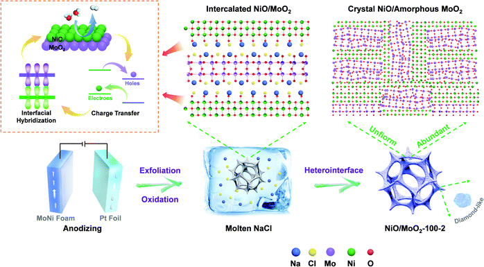
Inspired by all the above discussion, a self-supported crystal–amorphous NiO/MoO2 heterointerface directly derived from MoNi foam with a high-density interface has been prepared via a versatile molten-salt method assisted by anodizing. Scheme 1 schematically shows the synthesis process. The pre-anodizing of MoNi foam produces partly oxidized and stripped NiO/MoO2 species and disturbed surface structure (NiO/MoO2-100), which is conducive to subsequent molten salt treatment and morphological transformation. After being etched by molten salt, NiO/MoO2-100 becomes metastable and meanwhile forms a high-density NiO crystal/amorphous MoO2 interface on the brand new stripped layered structure, which is proved to facilitate electron transfer and intermediate adsorption/desorption with a low overpotential of 48 mV at 10 mA cm−2 and a small Tafel slope of 51.5 mV dec−1. DFT calculation also confirms the regulated charge arrangement near the Fermi energy, which is accompanied by the magnetic moment change. More importantly, the long-term durability further verifies the practicability of the molten-salt method, which provides new possibilities for high-performance catalyst design.
2. Experimental section
2.1. Chemicals
MoNi foam (thickness of 3 mm) was purchased from Kunshan Tengerhui Electronic Technology Co. Ltd. Ethanol (C2H5OH, AR), acetone (CH3COCH3, AR), dipotassium phosphate (K2HPO4), monopotassium phosphate (KH2PO4) and sodium chloride (NaCl) were purchased from Sinopharm Chemical Reagent Co. Ltd (Shanghai, China).2.2. Preparation of NiO/MoO2-s
NiO/MoO2-s was obtained by anodic oxidation of MoNi foam. The purchased MoNi foam was directly washed with hydrochloric acid, acetone, ethanol and deionized water for 30 min, respectively, and then vacuum dried for later use. Then the cut MoNi foam (1 × 2 cm) was oxidized by a three-electrode system at 0.5 V in phosphate buffer with a Pt plate as the counter electrode and a saturated calomel electrode as the reference electrode. The oxidized MoNi foam is denoted as NiO/MoO2-s (s indicates the anodic treatment time, seconds).2.3. Preparation of NiO/MoO2-s-h and Ni/Mo-h
The molten-salt method was proposed to produce the final NiO/MoO2-s-h. The above NiO/MoO2-s samples were immersed in molten NaCl at 800 °C for a certain time to acquire NiO/MoO2-s-h (h indicates the treatment time, hours).For comparison, Ni/Mo-h was synthesized by the same method as NiO/MoO2-s-h using MoNi foam without anodizing.
2.4. Preparation of NiO and MoO2
For comparison, NiO was synthesized by a similar procedure to NiO/MoO2-100-2 except for using nickel foam as the support. MoO2 was obtained by the same method as NiO/MoO2-100 with molybdenum foil as the substrate.3. Results and discussion
The final NiO/MoO2-100-2 sample with a NiO crystal/amorphous MoO2 heterostructure was fabricated by atypical two-step anodizing and molten-salt method process. The morphology transformation during this procedure is characterized by scanning electron microscopy (SEM) and transmission electron microscopy (TEM). For simplicity, NiO/MoO2-100-2 was screened as a representative sample for correlated analysis. As shown in Fig. S1a and b,† the commercial MoNi foam with a porous network structure possesses plenty of accumulated spherical clusters on the skeleton about 2.5 μm in diameter, and Mo and Ni are well mixed and distributed, benefiting the formation of high-density and homogeneous NiO/MoO2 interfaces. After anodic oxidation, the obtained NiO/MoO2-100 shows a relatively smooth surface where the nanoislands become fuzzy and tend to be flat (Fig. 1 and Fig. S1c and d†).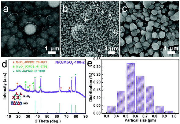 | ||
| Fig. 1 Structure characterization of NiO/MoO2-100 and NiO/MoO2-100-2. SEM images of (a) NiO/MoO2-100 and (b and c) NiO/MoO2-100-2. (d) XRD pattern and (e) particle distribution of NiO/MoO2-100-2. | ||
These activated surfaces with perturbed atomic arrangements are conducive to subsequent molten-salt method treatment. As expected, with two hours of immersion in molten NaCl (NiO/MoO2-100-2), the closely packed irregular diamond-like nanoparticles were easily detected, most of which are 600 nm in diameter (Fig. 1 and Fig. S2†). The significantly smaller nanoparticles undoubtedly contribute to the increase in the specific surface area, therefore creating enough active sites to promote hydrogen production. The crucial role of anodizing is further corroborated by Ni/Mo-2 samples (Fig. S3†), whose average larger-diameter (1200 nm) nanoparticles are merely the products of further growth of original clusters on pure MoNi foam with slight integration, unlike NiO/MoO2-100-2, which is the product of the relatively thorough post-integration growth. X-ray diffraction (XRD) is performed to identify the samples’ surface composition. Fig. S4a† first confirms that the main phase of MoNi foam is metallic Ni (JCPDS: 70-0989), while peaks of Mo species cannot be clearly discerned due to the shielding effect of the stronger peaks of Ni. For the resulting NiO/MoO2-100-2 (Fig. 1d), strong peaks at 37.1°, 43.2°, 62.9°, 75.4° and 79.4° match well with the (111), (200), (220), (311) and (222) crystal planes of NiO (JCPDS: 47-1049); and the signals of the (100), (−102), (122) and (−411) planes of MoO2 (JCPDS: 78-1071) can also be roughly detected at 18.4°, 31.6°, 63.8° and 73.0°. In addition, the MoO3 species can also be indexed at 27.4°, 29.6°, 35.6° and 42.4° (JCPDS: 01-0706) due to surface oxidation. These results suggest the coexistence of NiO and MoOx components. In addition, the broad peak may result from finely dispersed nano-sized particles or low crystallinity. Compared with NiO/MoO2-100 (Fig. S4b†), whose XRD peaks also show the presence of NiO, the diffraction pattern of NiO/MoO2-100-2 becomes diffuse and wider, which demonstrates more defects after molten salt treatment.
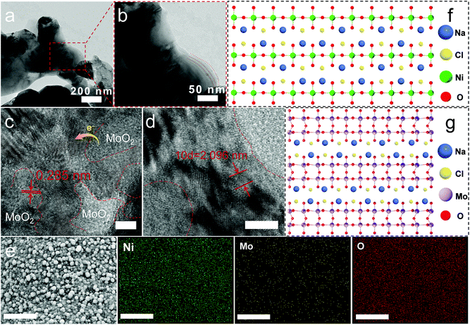
Interestingly, the TEM image of NiO/MoO2-100-2 stripped from the substrate shown in Fig. 2a and b clearly manifests the two-dimensional (2D) morphology, implying a previously well-verified phenomenon that during the reaction, molten NaCl can be inserted into NiO/MoO2 to form a 2D layered material.23,26 High-resolution TEM (Fig. 2c and d) confirms the presence of abundant NiO crystal/amorphous MoO2 heterointerfaces thanks to well mixed Mo and Ni in MoNi foam, where two lattice fringe spacings can be observed, belonging to the d-spacing of 0.209 nm for the (200) crystal plane of NiO and 0.284 nm of the (−102) plane for monoclinic MoO2, respectively, consistent with XRD analysis. In detail, Fig. S5† clearly shows the NiO/MoO2 interface, where the detected 0.209 and 0.241 nm belong to NiO while the ambiguous crystals with the distance of 0.218 and 0.147 nm come from MoO2.
The formation of the distinct crystals/amorphous in this work is mainly because of the unique MoNi foam, which is manufactured by deposition with a polymeric sponge as the substrate to form the Ni film–Ni coating–NiMo alloy structure. The Mo and Ni atoms in sandwich-like structures suffer from different moving rates to lead to the dense distribution of the heterophase. According to the earlier report, NiO can facilitate the dissociation of water in an alkaline electrolyte to generate active hydrogen, while amorphous areas are the active centers for hydrogen adsorption and desorption, thus synergistically boosting the HER process.10,11,27 It is worth mentioning that the lattice plane of MoO3 cannot be well observed due to the multi-defect structure. Note that the low valence-state Mo species are deemed to be active for the HER, and can serve as catalytic sites for hydrogen adsorption.14–16 Furthermore, SEM mapping (Fig. 2e) shows that Ni, Mo, and O are uniformly distributed in the selected field. Energy-dispersive X-ray spectroscopy (EDX) results in Fig. S6† show the elementary composition and contents. Notably, it shows a much lower Mo (2.64 At.%) content than Ni content (68.43 At.%), which may result from the different dynamic migration rates of Ni and Mo from the interior of the MoNi foam substrate to the surface in the molten salt system, which can be laterally confirmed by the higher compactness of the pure molybdenum plate than that of nickel foam. Next, the possible growth mechanism of the nanosheet structure is discussed and proposed as follows. First, according to the Arrhenius equation,28 the mathematical relationship of ka and kb that represents the reaction rate constant of supposed growth direction [001] and [100], respectively, is first expressed as below:
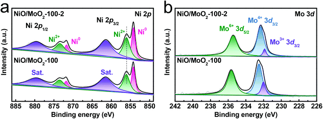
Further, X-ray photoelectron spectroscopy (XPS) is employed to investigate the surface composition of NiO/MoO2-100-2. The full scan spectrum confirms the presence of Ni, Mo, and O elements again (Fig. S7a†). The deconvoluted Ni 2p region contains two pairs of typical peaks accompanied by the satellite peaks (labeled as Sat.) (Fig. 3a), which can be reliably assigned to the NiO (2p3/2 at 856.1 eV and 2p1/2 at 873.4 eV) and Ni0 (2p3/2 at 854.1 eV and 2p1/2 at 871.6 eV) from the substrate.33–36 In the Mo 3d spectrum (Fig. 3b), the coexistence of Mo3+, Mo4+ and Mo6+ is substantiated by peaks at 231.9 eV, 232.3 eV and 235.6 eV, respectively.37,38 Moreover, the perturbed electronic structure on the surface of NiO/MoO2-100-2 via the molten-salt method can be discerned by the slight negative shift of Ni 2p (Fig. S7b†) and positive shift of Mo 3d peaks compared with the NiO/MoO2-100 precursor. The O 1s spectrum can be fitted into lattice oxygen (O1 at 529.7 eV), oxygen defects (O2 at 530.2 eV), and surface-adsorbed oxygen species (O3 at 531.7 eV), respectively (Fig. S7c†).39,40 The concentration of oxygen defects in the final catalyst increases to 35.6% from 31.4% of the precursor. The accumulated oxygen vacancies are conducive to electron rearrangement by acting as electron capture sites to regulate the coordination environments and electronic states of surface adsorbents. Meanwhile, the oxygen vacancies can activate their adjacent oxygen atoms toward hydrogen adsorption and facilitate water dissociation, in turn substantially improving the HER performance.41 These XPS results suggest the local rearranged electronic structure of NiO/MoO2-100-2 after the molten-salt method treatment.
The HER performance of all the prepared samples was also measured through three-electrode configuration in 1 M KOH. Fig. 4a shows the related polarization curves, and the target NiO/MoO2-100-2 exhibits the best HER activity with a required overpotential of 48 mV at 10 mA cm−2, superior to NiO/MoO2-100 (204 mV), Ni/Mo-2 (198 mV) and other reported NiO-based catalysts. Intriguingly, when the current density is above 18 mA cm−2, its activity is even better than that of the commercial Pt/C benchmark catalyst. The superiority of the NiO/MoO2 heterostructure is also highlighted by the lower HER activity of single NiO and MoO2 in Fig. S8.† Expectedly, the ratio of MoO2 to NiO has a significant impact on the HER activity, which is determined by the anodizing and molten-salt process. Thus, the influence of these two variables on the ratio of MoO2 and NiO and catalytic performance has been further investigated. In comparison, various anodizing times (50 s, 100 s, 150 s, and 200 s) are researched to clarify the role of pre-oxidation. As shown in Fig. S9a,† the HER performance of control samples increases first and then decreases rapidly with increasing anodic oxidation time, and the optimal time is 100 s, which can be reasonably attributed to the inadequate/excessive activation that leaves the induced NiO/MoO2 inappropriate (too much MoO2) for hydrogen evolution. Similarly, this reason can be applied to the phenomenon after changing the molten-salt method time, which results in excessive production of NiO (Fig. S9b†). Based on these, we speculate that the induced electron redistribution of the NiO/MoO2 heterointerface in the molten salt system is also accountable for the different HER performance. Besides, the water oxidation activity of the best-performing NiO/MoO2-100-2 is also acceptable (Fig. S10†). The corresponding Tafel slopes calculated from polarization curves are depicted in Fig. 4b to grant access to the HER kinetic process.42 The much smaller Tafel slope of 51.5 mV dec−1 for NiO/MoO2-100-2 than NiO/MoO2-100 (198.7 mV dec−1), Ni/Mo-2 (180.2 mV dec−1), Pt/C (56.7 mV dec−1) and other control materials indicates that the rate-determining step changes from the Volmer step to Volmer–Heyrovsky step.43 The influence of time of the molten-salt method and anodizing time exerted on the electron structure can be perceived by a series of Tafel plots (Fig. S11†). Furthermore, double-layer capacitance (Cdl) is evaluated by a range of cyclic voltammetry (CV) curves at 0.21 V vs. RHE (Fig. S12†) to assess the electrochemical active surface area. As expected, NiO/MoO2-100-2 has the highest Cdl value (Fig. 4d), indicating that the increased active sites play a significant role in activity enhancement. In order to set forth the contribution of the surface area and intrinsic activity of samples to the HER, we also normalized polarization curves by the electrochemical active surface area, as shown in Fig. S13.†NiO/MoO2-100-2 still shows admirable HER activity compared to the control sample NiO/MoO2-100 and Ni/Mo-2, indicating that the inherent activity of NiO/MoO2-100-2 improves due to the more intimate interactions between Ni and Mo caused by molten-salt treatment.
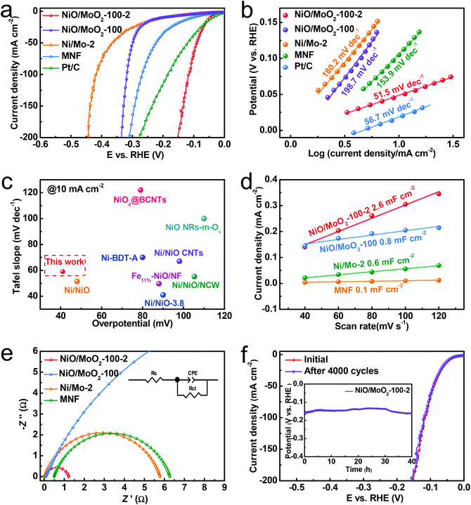 | ||
| Fig. 4 Electrochemical measurements of the obtained NiO/MoO2-100-2 sample in 1 M KOH. (a) Polarization curves and (b) the corresponding Tafel plots. (c) Comparison of the overpotential at 10 mA cm−2 and Tafel slope between NiO/MoO2-100-2 and the reported NiO-based catalysts (Table S1†). (d) Cdl value. (e) Nyquist plots fitted to the model inset. (f) Polarization curves of NiO/MoO2-100-2 before and after 4000 CV scans. The inset is the chronopotential curve at 100 mA cm−2. | ||
As a prevailing criterion for charge-transfer kinetics of the electrocatalytic process, electrochemical impedance spectroscopy (EIS) data are fitted via the inset circuit model shown in Fig. 4e and Fig. S14.† Obviously, as reflected from the semicircle diameter, the charge-transfer resistances of NiO/MoO2-100-2 are much lower than that of other samples, signifying the favorable charge transfer capability. In order to obtain an insight into the stability of NiO/MoO2-100-2 in the alkaline HER, the polarization curves before and after 4000 CV cycles are first collected in Fig. 4f and no distinct difference can be observed. Moreover, electrocatalytic HER is allowed to proceed for 40 h at a current density of 50 mA cm−2 with negligible degradation (illustrated in Fig. 4f). Fig. S15† shows that the morphology after the stability test remains unchanged and the crystal plane of NiO is well preserved, which together suggests the admirable durability benefitting from the inherent strong adhesion of the NiO/MoO2-100-2 catalyst using the substrate as the metal source. XRD also discerned the NiO and MoO2 phases after the 40 h HER tests (Fig. S16†), while the wider XRD peaks may indicate that the catalyst surface also consists of a NiO/MoO2 heterostructure with more defects. The Ni 2p XPS shifts to a lower bonding energy, meanwhile the Mo 3d XPS moves to higher bonding energy, and no new valence can be deconvoluted (Fig. S17a–c†). For the O 1s spectrum, the content of defective O further increases to 43.2%, implying the newly produced oxygen defects, which is in line with the XRD result. These characterization studies after HER measurement indicate that the surface of NiO/MoO2-100-2 is partially consumed under such a negative potential and alkaline electrolyte, and the newly formed defective species can still serve as highly efficient active centers.
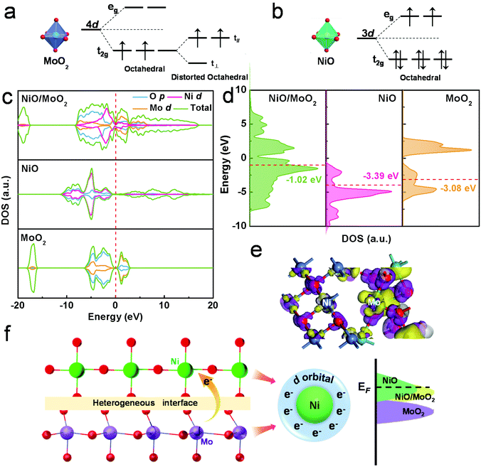
Furthermore, to gain a deeper insight into the significance of the integration of NiO and MoO2, it is necessary to figure out the spin state. According to the crystal field theory, when the electrons rearrange, the splitting of energy levels would result in additional energy. The Mo atom owns the 4d5 orbital with a higher energy level and it is a priority to be in a low spin state. Based on this, the possible electronic structure of MoO2 can be deduced as shown in Fig. 5a. The ligand field of Mo4+ can split the 4d orbital into t2g and eg sets, therefore the two electrons are prone to lie in the t2g orbit. Due to the asymmetric occupation in degenerate orbitals, the two electrons occupy the t∥ orbital, resulting in a lower energy level.44 Similar splits can happen to Ni2+, while the orbit structures of t62ge2g, and eg orbitals have been equally occupied, thus there is no further splitting (Fig. 5b).
In a nutshell, MoO2 and NiO both possess lone pair electrons. Previous reports have indicated that the lone pair electrons of nanomaterials can induce strong interactions between them, thus improving reactivity and stability via partial or entire electron-donating.45 In the present work, by means of a unique molten method, NiO can closely couple with MoO2 on the interface of NiO/MoO2, and the fluidity of unpaired electrons may lead to stronger electrical perturbations to enhance HER performance. Furthermore, the density of states (DOS) and partial DOS (PDOS) of the prepared catalysts were investigated within the density functional theory to verify the vital role of the NiO/MoO2 heterostructure for hydrogen evolution. The possible structures of NiO, MoO2 and NiO/MoO2 have been constructed and optimized, as shown in Fig. S18.† The calculated DOS shown in Fig. 5c suggests the favorable conductivity of NiO/MoO2 materials, and the d-electrons of Ni and Mo make the main contributions to the electron arrangement near the Fermi level. Besides, the level of the d-band center was also studied to quantify intuitively the electronic modulation.46 As Fig. 5d shows, the d-band center energies of NiO and MoO2 are −0.90 eV and −3.39 eV, respectively, which is too close or too far from the Fermi level, indicating that the metal–H bond is too strong or too weak to effectively desorb/trap hydrogen protons, thus resulting in low HER activity. Meanwhile, for the heterogeneous interface of NiO/MoO2, the d-electrons of the two rearrange and the d-band center energy is −1.02 eV, falling somewhere in between and manifesting moderate hydrogen adsorption. The adjusted electrons of the NiO/MoO2 interface are shown in Fig. 5e. The computed electron density difference shows the increased electron density (violet) of Ni atoms and decreased electron density (yellow) of Mo atoms, consistent with XPS results. Those results show that the electron distribution and energy band structures on the abundant interface of the NiO/MoO2 heterostructure can be effectively regulated, as schematically illustrated in Fig. 5f, thus coordinating the adsorption and desorption capacity of the catalyst surface to H, therefore finally improving the HER electrocatalytic activity. Combined with all the above discussions, the final NiO/MoO2-100-2 exhibits outstanding HER performance resulting from the optimized surface electron density and adsorption/desorption of intermediates as well as more available active sites.
4. Conclusions
In conclusion, a facile and practical anodizing-assisted molten-salt method has been proposed to construct a self-supported NiO/MoO2 heterostructure with high-density crystal–amorphous interfaces directly using MoNi foam as the metal source. The synthesized diamond-like NiO/MoO2-100-2 exhibits excellent HER performance in alkaline electrolytes, which can be ascribed to three main aspects: firstly, pre-anodizing ensures the activation of the inert surface of the substrate, thus facilitating the etching of subsequent molten salt to expose more active sites. Secondly, the formed high-density NiO crystal/amorphous MoO2 heterostructure can induce changes in electron density and band structure near the Fermi level to further optimize adsorption and desorption properties as well as charge transfer capability. In detail, NiO works for alkaline water dissociation, promoting the Volmer step to produce active hydrogen, which guarantees the smooth implementation of the subsequent Heyrovsky and Tafel steps at the amorphous area. Thirdly, the regulated electron state of NiO and MoO2 is also conductive to conductivity and adsorption capability optimization. This unique coupled crystal/amorphous structure, electron tailoring, and molten salt route are expected to provide new insights for advanced catalyst preparation.Conflicts of interest
There are no conflicts to declare.Acknowledgements
This work is financially supported by the National Natural Science Foundation of China (52174283) and the Shandong Provincial Natural Science Foundation (ZR2020MB044).References
- K. Yue, J. Liu, Y. Zhu, C. Xia, P. Wang, J. Zhang, Y. Kong, X. Wang, Y. Yan and B. Y. Xia, In situ ion-exchange preparation and topological transformation of trimetal-organic frameworks for efficient electrocatalytic water oxidation, Energy Environ. Sci., 2021, 14, 6546–6553 RSC.
- S. Meng, S. Sun, Y. Qi, D. Jiang, W. Wei and M. Chen, Synthesis of an iron-doped 3D-ordered mesoporous cobalt phosphide material toward efficient electrocatalytic overall water splitting, Inorg. Chem. Front., 2020, 7, 3002–3010 RSC.
- Y. Liu, Y. Yu, Z. Mu, Y. Wang, U. Ali, S. Jing and S. Xing, Urea-assisted enhanced electrocatalytic activity of MoS2-Ni3S2 for overall water splitting, Inorg. Chem. Front., 2020, 7, 3588–3597 RSC.
- X. X. Liu, K. L. Zhu, X. Zhang and P. Yang, MoS2 nanosheets coupled with double-layered hollow carbon spheres towards superior electrochemical activity, Electrochim. Acta, 2022, 407, 139929 CrossRef.
- H. Yang, L. Gong, H. Wang, C. Dong, J. Wang, K. Qi, H. Liu, X. Guo and B. Y. Xia, Preparation of nickel-iron hydroxides by microorganism corrosion for efficient oxygen evolution, Nat. Commun., 2020, 11, 5075 CrossRef CAS PubMed.
- D. Li, Y. Xing, C. Zhou, Y. Lu, S. Xu, X. Shi, D. Jiang and W. Shi, Iron and nitrogen Co-doped CoSe2 nanosheet arrays for robust electrocatalytic water oxidation, Inorg. Chem. Front., 2021, 8, 2725–2734 RSC.
- X. Zhang, P. Yang and S. P. Jiang, Horizontally growth of WS2/WO3 heterostructures on crystalline g-C3N4 nanosheets towards enhanced photo/electrochemical performance, J. Nanostruct. Chem., 2021, 11, 367–380 CrossRef CAS.
- X. Zhang, P. Yang and S. P. Jiang, Ni clusters-derived 2D/2D layered WOx(MoS2)/Ni-g-C3N4 step-scheme heterojunctions with enhanced photo- and electro-catalytic performance, J. Power Sources, 2021, 510, 230420 CrossRef CAS.
- Z. Wang, J. Bao, W. Liu, L. Xu, Y. Hu, M. Guan, M. Zhou and H. Li, Strong electronic coupled FeNi3/Fe2(MoO4)3 nanohybrids for enhancing the electrocatalytic activity for the oxygen evolution reaction, Inorg. Chem. Front., 2020, 7, 2791–2798 RSC.
- C. Zhang, Y. Xue, L. Hui, Y. Fang, Y. Liu and Y. Li, Graphdiyne@NiOx(OH)y heterostructure for efficient overall water splitting, Mater. Chem. Front., 2021, 5, 5305–5311 RSC.
- X. Y. Yu and X. W. Lou, Mixed Metal Sulfides for Electrochemical Energy Storage and Conversion, Adv. Energy Mater., 2018, 8, 1701592 CrossRef.
- P. Yan, Q. Liu, H. Zhang, L. Qiu, H. B. Wu and X. Y. Yu, Deeply reconstructed hierarchical and defective NiOOH/FeOOH nanoboxes with accelerated kinetics for the oxygen evolution reaction, J. Mater. Chem. A, 2021, 9, 15586–15594 RSC.
- E. L. Hu, Y. F. Feng, J. W. Nai, D. Zhao, Y. Hu and X. W. Lou, Construction of hierarchical Ni-Co-P hollow nanobricks with oriented nanosheets for efficient overall water splitting, Energy Environ. Sci., 2018, 11, 872–880 RSC.
- S. Geng, Y. Liu, Y. S. Yu, W. Yang and H. Li, Engineering defects and adjusting electronic structure on S doped MoO2 nanosheets toward highly active hydrogen evolution reaction, Nano Res., 2020, 13, 121–126 CrossRef CAS.
- M. Zheng, K. Guo, W. J. Jiang, T. Tang, X. Wang, P. Zhou, J. Du, Y. Zhao, C. Xu and J. S. Hu, When MoS2 meets FeOOH: A “one-stone-two-birds” heterostructure as a bifunctional electrocatalyst for efficient alkaline water splitting, Appl. Catal., B, 2019, 244, 1004–1012 CrossRef CAS.
- W. Zhang, Y. Tang, L. Yu and X. Y. Yu, Activating the alkaline hydrogen evolution performance of Mo-incorporated Ni(OH)2 by plasma-induced heterostructure, Appl. Catal., B, 2020, 266, 118154 CrossRef.
- Y. Zhai, X. Ren, J. Yan and S. Liu, High Density and Unit Activity Integrated in Amorphous Catalysts for Electrochemical Water Splitting, Small Struct., 2021, 2, 202000096 Search PubMed.
- L. Zhang, H. Zhao, S. Xu, Q. Liu, T. Li, Y. Luo, S. Gao, X. Shi, A. M. Asiri and X. Sun, Recent Advances in 1D Electrospun Nanocatalysts for Electrochemical Water Splitting, Small Struct., 2021, 2, 2000048 CrossRef CAS.
- B. Dong, J. Y. Xie, N. Wang, W. K. Gao, Y. Ma, T. S. Chen, X. T. Yan, Q. Z. Li, Y. L. Zhou and Y. M. Chai, Zinc ion induced three-dimensional Co9S8 nano-neuron network for efficient hydrogen evolution, Renewable Energy, 2020, 157, 415–423 CrossRef CAS.
- Z. Yan, H. Sun, X. Chen, H. Liu, Y. Zhao, H. Li, W. Xie, F. Cheng and J. Chen, Anion insertion enhanced electrodeposition of robust metal hydroxide/oxide electrodes for oxygen evolution, Nat. Commun., 2018, 9, 2373 CrossRef PubMed.
- Z. L. Zhao, Q. Wang, X. Huang, Q. Feng, S. Gu, Z. Zhang, H. Xu, L. Zeng, M. Gu and H. Li, Boosting Oxygen Evolution Reaction Using Defect-rich Ultra-Thin Ruthenium Oxide Nanosheets in Acidic Media, Energy Environ. Sci., 2020, 13, 5143–5151 RSC.
- M. Xiao, L. Zhang, B. Luo, M. Lyu, Z. L. Wang, H. M. Huang, S. C. Wang, A. J. Du and L. Z. Wang, Molten-Salt-Mediated Synthesis of an Atomic Nickel Co-catalyst on TiO2 for Improved Photocatalytic H2 Evolution, Angew. Chem., Int. Ed., 2020, 59, 7230–7234 CrossRef CAS PubMed.
- H. Y. Jin, Q. F. Gu, B. Chen, C. Tang, Y. Zheng, H. Zhang, M. Jaroniec and S. Z. Qiao, Molten Salt-Directed Catalytic Synthesis of 2D Layered Transition-Metal Nitrides for Efficient Hydrogen Evolution, Chem, 2020, 6, 2382–2394 CAS.
- W. W. Han, L. L. Chen, B. Ma, J. Wang, W. Y. Song, X. B. Fan, Y. Li, F. B. Zhang and W. C. Peng, Ultra-small Mo2C nanodots encapsulated in nitrogen-doped porous carbon for pH-universal hydrogen evolution: insights into the synergistic enhancement of HER activity by nitrogen doping and structural defects, J. Mater. Chem. A, 2019, 7, 4734–4743 RSC.
- C. H. Zhang and L. M. Dai, Targeted Defect Synthesis for Improved Electrocatalytic Performance, Chem, 2020, 6, 1849–1851 CAS.
- G. Qian, G. Yu, J. Lu, L. Luo, T. Wang, C. Zhang, R. Ku, S. Yin, W. Chen and S. Mu, Ultra-thin N-doped-graphene encapsulated Ni nanoparticles coupled with MoO2 nanosheets for highly efficient water splitting at large current density, J. Mater. Chem. A, 2020, 8, 14545–14554 RSC.
- Z. H. Dong, F. Lin, Y. H. Yao and L. F. Jiao, Crystalline Ni(OH)2/Amorphous NiMoOxMixed-Catalyst with Pt-Like Performance for Hydrogen Production, Adv. Energy Mater., 2019, 9, 1902703 CrossRef CAS.
- F. Q. He, X. H. Deng and M. Chen, Mechanism and kinetics of Fe(II) EDTA-NO reduction by iron powder under anaerobic condition, Fuel, 2016, 186, 605–612 CrossRef CAS.
- H. Wang, H. Yuan, S. S. Hong, Y. Li and Y. Cui, Physical and chemical tuning of two-dimensional transition metal dichalcogenides, Chem. Soc. Rev., 2015, 44, 2664–2680 RSC.
- D. Voiry, A. Mohite and M. Chhowalla, Phase engineering of transition metal dichalcogenides, Chem. Soc. Rev., 2015, 44, 2702–2712 RSC.
- Z. M. Hu, X. Xiao, H. Y. Jin, T. Q. Li, M. Chen, Z. Liang, Z. F. Guo, J. Li, J. Wan, L. Huang, Y. R. Zhang, G. Feng and J. Zhou, Rapid mass production of two-dimensional metal oxides and hydroxides via the molten salts method, Nat. Commun., 2017, 8, 15630 CrossRef CAS PubMed.
- H. Sun, Z. Yan, F. Liu, W. Xu, F. Cheng and J. Chen, Self-Supported Transition-Metal-Based Electrocatalysts for Hydrogen and Oxygen Evolution, Adv. Mater., 2020, 32, 1806326 CrossRef CAS PubMed.
- C. G. Kuai, Y. Zhang, L. L. Han, H. L. Xin, C. J. Sun, D. Nordlund, S. Z. Qiao, X. W. Du and F. Lin, Creating compressive stress at the NiOOH/NiO interface for water oxidation, J. Mater. Chem. A, 2020, 8, 10747–10754 RSC.
- X. Zhang, P. Yang and S. P. Jiang, Ni diffusion in vertical growth of MoS2 nanosheets on carbon nanotubes towards highly efficient hydrogen evolution, Carbon, 2021, 175, 176–186 CrossRef CAS.
- X. Zhao, J. Meng, Z. Yan, F. Cheng and J. Cheng, Nanostructured NiMoO4 as active electrocatalyst for oxygen evolution, Chin. Chem. Lett., 2019, 30, 319–323 CrossRef CAS.
- K. Guo, Y. Wang, J. Huang, M. Lu, H. Li, Y. Peng, P. Xi, H. Zhang, J. Huang, S. Lu and C. Xu, In Situ Activated Co3−xNixO4 as a Highly Active and Ultrastable Electrocatalyst for Hydrogen Generation, ACS Catal., 2021, 11, 8174–8182 CrossRef CAS.
- G. J. Liu, H. P. Bai, Y. J. Ji, L. Wang, Y. Z. Wen, H. P. Lin, L. R. Zheng, Y. Y. Li, B. Zhang and H. S. Peng, A highly efficient alkaline HER Co-Mo bimetallic carbide catalyst with an optimized Mo d-orbital electronic state, J. Mater. Chem. A, 2019, 7, 12434–12439 RSC.
- B. R. Garrett, S. M. Polen, M. Pimplikar, C. M. Hadad and Y. Wu, Anion-Redox Mechanism of MoO(S2)2(2,2′-bipyridine) for Electrocatalytic Hydrogen Production, J. Am. Chem. Soc., 2017, 139, 4342–4345 CrossRef CAS PubMed.
- W. B. Hu, Y. Liu, R. L. Withers, T. J. Frankcombe, L. Norén, A. Snashall, M. Kitchin, P. Smith, B. Gong, H. Chen, J. Schiemer, F. Brink and J. Wong-Leung, Electron-pinned defect-dipoles for high-performance colossal permittivity materials, Nat. Mater., 2013, 12, 821–826 CrossRef CAS PubMed.
- X. Chen, L. Liu, P. Y. Yu and S. S. Mao, Increasing solar absorption for photocatalysis with black hydrogenated titanium dioxide nanocrystal, Science, 2011, 331, 746–750 CrossRef CAS PubMed.
- S. H. Jiang, R. Y. Zhang, H. X. Liu, Y. Rao, Y. N. Yu, S. Chen, Q. Yue, Y. N. Zhang and Y. J. Kang, Promoting Formation of Oxygen Vacancies in Two-Dimensional Cobalt-Doped Ceria Nanosheets for Efficient Hydrogen Evolution, J. Am. Chem. Soc., 2020, 142, 6461–6466 CrossRef CAS PubMed.
- T. Shinagawa, A. T. Garcia-Esparza and K. Takanabe, Insight on Tafel slopes from a microkinetic analysis of aqueous electrocatalysis for energy conversion, Sci. Rep., 2015, 5, 13801 CrossRef PubMed.
- K. Xu, H. Ding, M. X. Zhang, M. Chen, Z. K. Hao, L. D. Zhang, C. Z. Wu and Y. Xie, Regulating Water-Reduction Kinetics in Cobalt Phosphide for Enhancing HER Catalytic Activity in Alkaline Solution, Adv. Mater., 2017, 29, 1606980 CrossRef PubMed.
- J. B. Goodenough, Metallic oxides, Prog. Solid State Chem., 1971, 5, 145–399 CrossRef CAS.
- X. Liu, K. Chen, X. Y. Li, Q. C. Xu, J. Weng and J. Xu, Electron Matters: Recent Advances in Passivation and Applications of Black Phosphorus, Adv. Mater., 2021, 33, 202005924 Search PubMed.
- C. Wei, Y. M. Sun, G. G. Scherer, A. C. Fisher, M. Sherburne, J. W. Ager and Z. C. Xu, Surface Composition Dependent Ligand Effect in Tuning the Activity of Nickel-Copper Bimetallic Electrocatalysts toward Hydrogen Evolution in Alkaline, J. Am. Chem. Soc., 2020, 142, 7765–7775 CrossRef CAS PubMed.
Footnote |
| † Electronic supplementary information (ESI) available. See DOI: https://doi.org/10.1039/d2qi00136e |
| This journal is © the Partner Organisations 2022 |

