 Open Access Article
Multiple “Hot exciton” channel molecular design in organic electroluminescence materials: a theoretical investigation†
Yuyu
Pan
 *ab,
Yao
Guo
a,
Mei
Zhao
a,
Chang
Li
a and
Bing
Yang
 *c
*c
aSchool of Petrochemical Engineering, Shenyang University of Technology, 30 Guanghua Street, Liaoyang, 111003, P. R. China. E-mail: pyy39518768@163.com
bState Key Laboratory of Luminescent Materials and Devices, South China University of Technology, Guangzhou 510640, China
cState Key Laboratory of Supramolecular Structure and Materials, Jilin University, Changchun, 130012, P. R. China. E-mail: yangbing@jlu.edu.cn
First published on 15th January 2021
Abstract
The “Hot exciton” channel material can take into account both maximizing exciton utilization efficiency (EUE) and maximizing photoluminescent quantum yield (PLQY). It is a new material with broad application prospects. In this article, starting from the classical D–A molecular model system, the long-range correction functional ωb97x, which can accurately describe the CT state, was selected for the excited state calculation. We extended the D–A system to the X-B-D system. In order to preserve the large ΔET1–T2, we selected the NZ group as the central core B; we chose a donor group 10H-phenoxazine (X1) and an acceptor group 1,3,4,6,7,9,9b-heptaazap-henalene (X2) as part X, and 10 donors with different HOMO as part D. By simulating the ground state and excited state properties of these 20 molecules, we found that compared with the traditional D–A molecule, the excited state of the X-B-D molecules underwent more CT or HLCT transition; the number of channels for the reverse intersystem crossing increased from one to multiple, which may provide a new idea for the design of new multi-channel “Hot exciton” materials.
Introduction
The “Hot exciton” mechanism is based on the reverse intersystem crossing (RISC) process associated with the small energy gap (ΔEST) between the high-lying triplet state (T) and the energetically similar singlet state (S).1–5 The traditional spin–statistics rule limitation (25%) can be overcome via this mechanism as it removes large numbers of excitons from the triplet state to the singlet state. It is possible to achieve the largest photoluminescent quantum yield (PLQY) and exciton utilization efficiency (EUE). Since Ma's group developed the “Hot exciton” mechanism in 2012, it has aroused the enthusiasm of researchers.6–10In fact, there are three basic principles for the ideal “Hot exciton” molecular structure and excited state distribution: (i) the molecule has at least two parts that can be tuned, namely, the donor–acceptor (D–A) structure; the interaction between D and A should not be too strong (to avoid the charge-transfer (CT) state becoming the lowest excited state), nor should it be too weak (the CT state cannot be formed effectively). (ii) The lowest excited states S1 and T1 can be guaranteed to possess the localized excited state (LE) characteristics, and their large wave function overlaps between electron and hole are used to ensure a high probability of radiative transition of the S1 state, thereby improving the PLQY of the compound; on the other hand, Sn(n>1) and Tm(m>1) have significant CT state characteristics, so that they can achieve a sufficiently small ΔESn–Tm by overlapping the small electron and hole wave functions, and complete the RISC (Tm → S1 or Tm → Sn(n, m≥2)) process. (iii) There is a sufficiently large energy gap between the high-level triplet excited-states (ΔETm–Tm−1) responsible for reducing the rate of the internal conversion (IC) process (Tm → Tm−1) effectively, which makes the rate of the RISC sufficient to compete with it, and eventually causes the relaxation path of the T exciton change from the T1 state.11–13 This can also effectively prevent the generation and accumulation of the T exciton and overcome the T–T annihilation in the organic phosphorescent materials and the thermally activated delay fluorescence (TADF) materials that causes a serious roll-off in the device under high current density. At present, most of the “Hot exciton” materials are concentrated in the hybridized local and charge transfer (HLCT) materials.7,11,14,15 The most notable feature of HLCT is the combined and compatible transition of the LE and CT states. The LE component in the hybrid state can guarantee a high radiative transition rate, and the weak binding energy of the CT state component can lead to a small ΔEST, which provides the possibility for RISC of the T exciton.
Nevertheless, there are two main challenges for the “Hot exciton” materials. The first is that the high-lying CT states cannot be constructed effectively. The other is that few molecules have large ΔETm–Tm−1, and maintaining this gap is not easy. Many studies revealed that the D–A design is the best approach to develop “Hot exciton” emitters. However, there are few CT states in the singlet and triplet excited states (1CT and 3CT state) in these simple D–A molecules, which means that the “Hot exciton” channel could not be guaranteed to be efficient and unobstructed. Here, the key point is to expand the molecular structure on the basis of ensuring the large ΔETm–Tm−1, and add multiple channels for RISC, aiming at the achievement of high PLQY and EUE.
Molecular design strategy
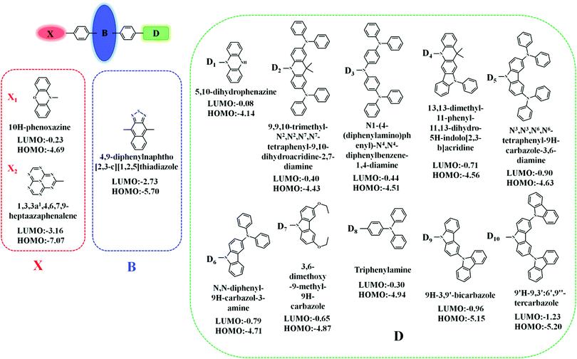
In this contribution, we proposed a new approach for the design of “Hot exciton” molecules that may exhibit faster and more efficient RISC. To validate our strategy in this study, we designed a series of X-B-D molecules. In order to ensure a large ΔETm–Tm−1, we chose naphthothiadiazole (NZ) as the core part B; as part D, we selected a series of donor groups according to their strengths, specifically referring to their energy of the highest occupied molecular orbital (HOMO) (EH), where deep EH implies weak electron donor strength, while shallow EH indicates strong electron donor strength. For the third part X, we chose a donor group, 10H-phenoxazine (X1), and an acceptor group, 1,3,4,6,7,9,9b-heptaazaphenalene (X2), to reduce the steric hindrance; the benzene ring connects to the 4, 9 positions of the NZ separately with a single bond, as shown in Fig. 1.8 The structural versatility of the heteroatomic moiety allowed us to systematically investigate the rational design of a novel candidate for “Hot exciton” luminescent and charge transport materials for OLED. By applying density functional theory (DFT) and time-dependent DFT (TD-DFT) methodology, we calculated the electronic structures of the excited states, including the energy level structure and the transition configuration details of the designed molecules. It is anticipated that our study could provide valuable information for the design of novel luminescent materials for OLEDs.Methodology and computational details
As we know, a shortage of experimentally determined energy levels and transition properties of the excited state restrain the further understanding of the mechanism and the development of the “Hot exciton” materials. However, fortunately, theoretical calculations and molecular simulations have played a vital role in the study of the formation mechanism of excited states. There are some commonly used methods that describe the electronic structures of the excited states in the CIS (configuration interaction with single substitution), EOM-CCSD (equation of motion coupled cluster with single and double excitations), and TD-DFT (time-dependent density functional theory).16–18 In comparison, TD-DFT is a cost-effective calculation method. However, the TD-DFT method is very sensitive to functionals. Therefore, in the previous work, we calculated and simulated the molecular configuration, absorption spectrum, and emission spectrum of some HLCT state molecules in vacuum and solvent by 2 local functionals (SVWN and PBE), 7 hybrid functionals (BLYP, B3LYP, PBE0, BMK, BHHLYP, M06-2X, and M06HF), and one long-range-corrected functional, ωB97X, and then compared them with the experimental value. The ωb97x functional can provide an accurate quantitative description of the charge transfer excited state properties.19–23 From the above research, we conclude that ωB97X is an ideal functional for calculating the HLCT molecule. We optimized the geometrical and electronic structures of the singlet/triplet states by the TD-DFT/ωb97x/6-31G(d,p) approach, as implemented in the Gaussian 09.D.01 revision.24In addition, the calculation of the spin–orbit coupling and transition rate, and the charge transfer ratio with the help of MOMAP, Multiwfn, and BDF software can further explore the properties of some photophysical processes between the excited states.25–27
Results and discussions
Optimized geometries of ground-state
As designed, the new X-B-D molecules are composed of three parts. This configuration makes these three parts have large torsion angles between 50° and 70° in their S0 configuration, and it is easier to form the intramolecular CT state with such configuration; these optimization structures are illustrated in Fig. S1 (ESI†).Properties of frontier molecular orbitals (FMOs)
We investigated the properties of frontier molecular orbitals (FMOs) of the newly designed molecules, as illustrated in Fig. 2. The contour plots of the HOMOs are primarily localized on the electron-donating moiety, with lower EH, whereas the lowest unoccupied molecular orbitals (LUMOs) were entirely localized in the electron-accepting NZ moiety. That is, a large separation of the HOMO and LUMO in these molecular configurations formed.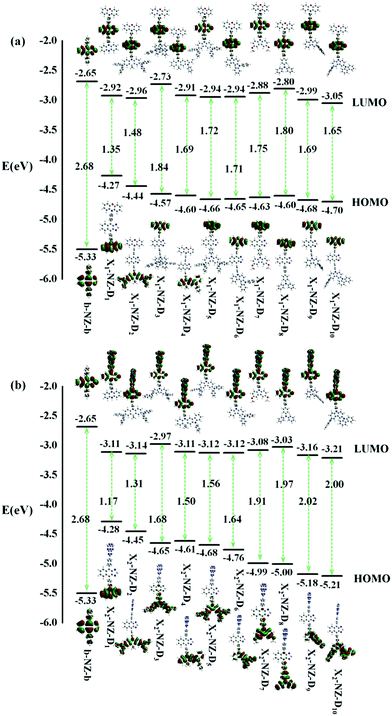 | ||
| Fig. 2 The energy levels of the frontier molecular orbitals (FMOs), the contour plots of the HOMO and LUMO of designed molecules, (a) b-NZ-b and X1-B-D1–10; (b) b-NZ-b and X2-B-D1–10. | ||
In most cases, an electron is promoted from the HOMO to the LUMO to form the first singlet excited-state (S1). The ΔEST value is decided by the overlap integral of the HOMO and LUMO of the emitters, and a small overlap of the HOMO and LUMO favors a small ΔEST value. In other words, the ΔEST value can be reduced by decreasing the HOMO and LUMO overlap, which can be accomplished by spatially separating the HOMO and LUMO through D–A structures or conjugation-breaking molecular structures. The D–A structures were employed to obtain the small ΔEST in the “Hot exciton” emitters. However, the S1 transition of some molecules does not necessarily exhibit a transition from the HOMO to the LUMO, and so other transfer pathways, such as HOMO → LUMO+1, HOMO−1 → LUMO+1, HOMO−2 → LUMO+1, and HOMO−3 → LUMO+1, can also be considered. Therefore, if there are multiple charge transfer states with similar energy in the excited states of molecules, then multiple RISC channels can be constructed to ensure efficient transmission of excitons. At the same time, if the molecules have large ΔETm–Tm−1, then the utilization of the yields of singlet exciton can be greatly improved in theory.
Excited state characteristics
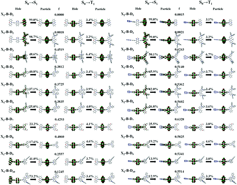
In theory, the transition properties of the excited states are usually determined by the magnitude of the transition dipole moment (μ) and the distribution of the electron cloud of the natural transition orbitals (NTOs).26 We illustrated the μ and the dominant “hole”-“particle” contributions of the NTOs of these designed molecules in Fig. 3, Fig. SII and Tables S1, S2 (ESI†).As for the electron transition character of S1 and T1 states, NTOs were evaluated on the molecules, as shown in Fig. 3. Firstly, both the ‘‘hole’’ and ‘‘particle’’ of T1 states were localized on part B, the core of the molecular backbone, independent of different X and D. Obviously, they all exhibit a π–π* type LE state character. In contrast, S1 states undergo significant changes relative to those of the counterparts upon the incorporation of the D group. To be more specific, the left of Fig. 3 shows the NTOs of the X1-B-D1–10 series. With the weakening of the electron-donating ability of part D, the electron transition character of the S1 state shows a tendency to change from the CT (transited from part D to part B) state to the HLCT state, which was formed by the hybridization of the LE state located on B and CT state transition from D to B, and to another HLCT state, which was formed by the hybridization of the LE state located on B and CT state transition from X to B. We also calculated the charge transfer ratio of the excited state. We divided the molecule into five fragments and calculated the charge transfer among them. The charge transfer ratio of the S1 and T1 states are shown by the arrows in Fig. 3. The charge transfer ratio of the S2–S10 and T2–T10 states are shown in Fig. SII (ESI†), and the specific charge transfer ratio between each fragment are shown in Fig. SIII (ESI†). Moreover, we can also see that the charge transfer ratio is consistent with the NTOs. At the same time, the strength of the oscillator (f) shows a tendency to increase first and then decrease. When part X changes into X2, the trend of the transition characteristics was basically the same as that of X1, which is the change from the CT state to the HLCT state and then to the LE state located on the NZ part, but due to X2, it shows the properties of an electron acceptor, and thus the transition does not occur on part X2.
However, the S1 and T1 states in the above transitions do not exhibit the same CT transition, and this must be caused due to large ΔES1–T1, which, in turn, implies slow kRISC between them. Therefore, in this case, if the T exciton returns to the singlet state through the RISC, there must be an exciton channel at a higher energy level. We drew the NTOs of the first ten excited states of this series of molecules in SII, respectively. As shown in the figures, there were many CT states in the S2–S10 and T2–T10. This suggests that there may be many “Hot exciton” channels in the higher-lying excited states in these molecules. To shed light on the key factors that govern the exciton RISC process, the excited state energy diagrams of these molecules were analyzed carefully, including the first ten singlet and triplet excited states (Fig. 4 and 5).
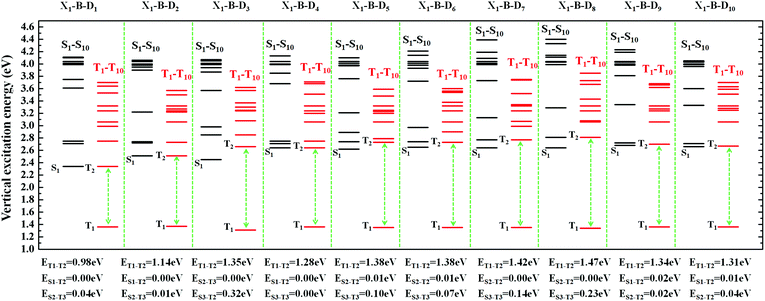 | ||
| Fig. 4 The excited state energy diagrams of X1-B-D1-10, including the first ten singlet and ten triplet excited states, respectively. | ||
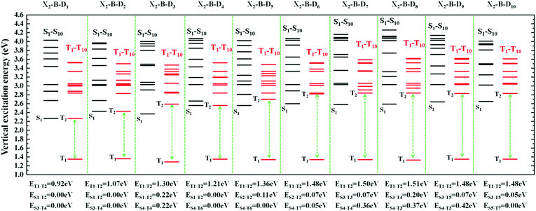 | ||
| Fig. 5 The excited state energy diagrams of X2-B-D1–10, including the first ten singlet and ten triplet excited states, respectively. | ||
In order to facilitate the observation, combined with the excited state NTOs, we listed the ΔE value between excited states with similar CT state transition in Fig. 3. It can be seen from Fig. 4 and 5 that since the central part of the molecule was NZ, this series of molecules maintained a large ΔET1–T2 (0.92–1.51 eV) in the triplet states, which greatly reduced the IC rate of the triplet excitons. In addition, there were at least two CT states with similar transitions in the first 5 excited states, and the ΔEST value was very small (≈0 eV). Such small ΔEST values ensure the clearance of the “Hot exciton” channel, and the simultaneous existence of multiple channels may further improve the efficiency of the RISC in the triplet excitons.
The RISC rate is proportional to the singlet–triplet energy gap (ΔEST) and spin-orbital coupling (SOC) of the matrix element. The hot exciton emitters have almost zero singlet–triplet energy gap in the higher excited state. So, the stronger SOC will enhance the RISC rate constant, according to the Fermi Golden rule. However, the SOC in pure organic molecules is generally relatively small, less than 1 cm−1, which is much smaller than the SOC in phosphorescent molecules with metallic materials (about 100 cm−1). Therefore, we calculated the SOC between the first 5 singlet states and their adjacent triplet states of the designed molecules. The values are listed in Table S2 (ESI†). From the table, we can find that due to the lack of d orbitals in the atoms of these organic molecules, the SOC was relatively small, but there are many SOC, between singlet states and the adjacent triplet states that exceeded 0.5 cm−1, and we have marked them in the table, especially S5 in the X1-NZ-D1–10 series, and S1 and S5 in the X2-NZ-D1–10 series. This shows that these designed molecules have both a small ΔEST and large SOC, which provides conditions for RISC. However, with the decrease in the EH of the donor group and higher excitation energy, the CT state components were smaller, with a greater proportion of LE states, due to which the coupling between the excited states increased significantly. This also provides a guarantee for the reverse intersystem crossing of excitons. Therefore, as shown in Fig. 6, compared with the traditional “Hot exciton” type molecule, the X-NZ-D type molecule not only maintains a larger ΔET1–T2 but also increases the exciton channel from a one-to-one band. This provides a greater possibility for the RISC of excitons.
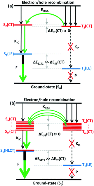 | ||
| Fig. 6 A simple scheme of (a) the traditional “Hot exciton” mode and (b) the multi-channel “Hot exciton” mode in the electroluminescence process. Here, F: fluorescence; P: phosphorescence. | ||
Conclusions
We have unravelled a molecular design concept of multiple “Hot exciton” channels in organic electroluminescent materials and predicted their photoelectrical properties. The theoretical investigations were implemented by using the X-B-D framework molecules, which consisted of the NZ core as part B, a donor group 10H-phenoxazine (X1) and an acceptor group 1,3,4,6,7,9,9b-heptaazap-henalene (X2), which are used as part X, and in part D, we selected a series of donor groups according to their electron donor strength. After simulating the excited state properties of the molecules using the TD-DFT method, we found that on the basis of ensuring a large ΔET1–T2, the introduction of different parts on both sides of the NZ, the proportion of CT states was increased. There are multiple CT state transitions in the first ten singlet states and triplet state, which provide a guarantee for the RSIC of the triplet excitons. At the same time, such molecules have a large SOC, which can also ensure their “hot” excitonic channels. In addition, our results validated the concept of multi-channel “Hot exciton” mode, as compared to other OLED molecules, potentially leading to a wide range of next-generation OLED materials by combining high EUE and maximizing PLQY. More experiments and theories should be joined together to develop the multi-channel “Hot exciton” mode and to further expand its applications.Conflicts of interest
There are no conflicts to declare.Acknowledgements
This work was supported by the Scientific Research Funding Project of Education Department of Liaoning Province (No. LQGD2019011) and the National Natural Science Foundation of China (No. 51603127).Notes and references
- H. Uoyama, K. Goushi, K. Shizu, H. Nomura and C. Adachi, Nature, 2012, 492, 234 CrossRef CAS PubMed.
- S. Y. Lee, T. Yasuda, Y. S. Yang, Q. S. Zhang and C. Adachi, Angew. Chem., Int. Ed., 2014, 53, 6402 CrossRef CAS PubMed.
- J. Li, T. Nakagawa, J. MacDonald, Q. Zhang, H. Nomura, H. Miyazaki and C. Adachi, Adv. Mater., 2013, 25, 3319 CrossRef CAS PubMed.
- G. Méhes, H. Nomura, Q. Zhang, T. Nakagawa and C. Adachi, Angew. Chem., Int. Ed., 2012, 51, 11311 CrossRef PubMed.
- Y. W. Xu, P. Xu, D. H. Hu and Y. G. Ma, Chem. Soc. Rev., 2021 10.1039/D0CS00391C.
- L. Yao, S. T. Zhang, R. Wang, W. J. Li, F. Z. Shen, B. Yang and Y. G. Ma, Angew. Chem., Int. Ed., 2014, 126, 2151 CrossRef.
- W. J. Li, Y. Y. Pan, R. Xiao, Q. M. Peng, S. T. Zhang, D. G. Ma, F. Li, F. Z. Shen, Y. H. Wang, B. Yang and Y. G. Ma, Adv. Funct. Mater., 2014, 24, 1609 CrossRef CAS.
- Y. Y. Pan, W. J. Li, S. T. Zhang, L. Yao, C. Gu, H. Xu, B. Yang and Y. G. Ma, Adv. Opt. Mater., 2014, 2, 510 CrossRef CAS.
- H. C. Liu, Q. Bai, L. Yao, H. Y. Zhang, H. Xu, S. T. Zhang, W. J. Li, Y. Gao, J. Y. Li, P. Lu, H. Y. Wang and B. Yang, Chem. Sci., 2015, 6, 3797 RSC.
- S. F. Xue, X. Qiu, S. A. Ying, Y. S. Lu, Y. Y. Pan, Q. K. Sun, C. Gu and W. J. Yang, Adv. Opt. Mater., 2017, 5, 1700747 CrossRef.
- Y. W. Xu, X. M. Liang, X. H. Zhou, P. Yuan, J. D. Zhou, C. Wang, B. B. Li, D. H. Hu, X. F. Qiao, X. F. Jiang, L. L. Liu, S. J. Su, D. G. Ma and Y. G. Ma, Adv. Mater., 2019, 31, 1807388 CrossRef PubMed.
- L. Yao, B. Yang and Y. G. Ma, Sci. China: Chem., 2014, 57, 335 CrossRef CAS.
- D. H. Hu, L. Yao, B. Yang and Y. G. Ma, Philos. Trans. Math. Phys. Eng. Sci., 2015, 373, 20140318 Search PubMed.
- J. Jayabharathi, J. Anudeebhana, V. Thanikachalam and S. Sivaraj, RSC. Adv., 2020, 10, 8866 RSC.
- B. Liu, Z. W. Yu, D. He, Z. L. Zhu, J. Zheng, Y. D. Yu, W. F. Xie, Q. X. Tong and C. S. Lee, J. Mater. Chem. C, 2017, 5, 5402 RSC.
- J. B. Foresman and M. J. Frisch, Exploring Chemistry with Electronic Structure Methods, Gaussian, Inc., Pittsburgh, PA, 2nd edn, 1996 Search PubMed.
- G. E. Scuseria and H. F. Schaefer III, J. Chem. Phys., 1989, 90, 3700 CrossRef CAS.
- A. D. Boese and J. M. L. Martin, J. Chem. Phys., 2004, 121, 3405 CrossRef CAS PubMed.
- P. Foggi, F. V. Neuwahl, R. L. Moroni and P. R. Salvi, J. Phys. Chem. A, 2003, 107, 1689 CrossRef CAS.
- G. E. Scuseria, III and H. F. J. Schaefer, J. Chem. Phys., 1989, 90, 3700 CrossRef.
- Y. Y. Pan, J. Huang, S. T. Zhang, D. W. Yu, B. Yang and Y. G. Ma, RSC Adv., 2016, 6, 108404 RSC.
- M. E. Casida, C. Jamorski, K. C. Casida and D. R. Salahub, J. Chem. Phys., 1998, 108, 4439 CrossRef CAS.
- R. E. Stratmann, G. E. Scuseria and M. J. Frisch, J. Chem. Phys., 1998, 109, 8218 CrossRef CAS.
- M. J. Frisch, G. W. Trucks, H. B. Schlegel, G. E. Scuseria, M. A. Robb, J. R. Cheeseman, G. Scalmani, V. Barone, B. Mennucci, G. A. Petersson, H. Nakatsuji, M. Caricato, X. Li, H. P. Hratchian, A. F. Izmaylov, J. Bloino, G. Zheng, J. L. Sonnenberg, M. Hada, M. Ehara, K. Toyota, R. Fukuda, J. Hasegawa, M. Ishida, T. Nakajima, Y. Honda, O. Kitao, H. Nakai, T. Vreven, J. A. Montgomery Jr., J. E. Peralta, F. Ogliaro, M. Bearpark, J. J. Heyd, E. Brothers, K. N. Kudin, V. N. Staroverov, R. Kobayashi, J. Normand, K. Raghavachari, A. Rendell, J. C. Burant, S. S. Iyengar, J. Tomasi, M. Cossi, N. Rega, J. M. Millam, M. Klene, J. E. Knox, J. B. Cross, V. Bakken, C. Adamo, J. Jaramillo, R. Gomperts, R. E. Stratmann, O. Yazyev, A. J. Austin, R. Cammi, C. Pomelli, J. W. Ochterski, R. L. Martin, K. Morokuma, V. G. Zakrzewski, G. A. Voth, P. Salvador, J. J. Dannenberg, S. Dapprich, A. D. Daniels, Ö. Farkas, J. B. Foresman, J. V. Ortiz, J. Cioslowski and D. J. Fox, Gaussian 09 (Revision D.01), Gaussian, Inc., Wallingford, CT, 2009 Search PubMed.
- Z. Li, Y. Xiao and W. Liu, Mol. Phys., 2013, 111, 3741 CrossRef CAS.
- F. Wu, W. Liu, Y. Zhang, Z. Li and J. Chem, Theor. Comput., 2011, 7, 3643 CrossRef CAS PubMed.
- T. Lu and F. W. Chen, J. Comput. Chem., 2012, 33, 580 CrossRef CAS PubMed.
Footnote |
| † Electronic supplementary information (ESI) available: Molecular optimal configuration, natural transition orbitals (NTOs), transition energy (ES, ET), transition dipole moment (λ) of the first 10 excited states, and the spin–orbit coupling (SOC) between excited states. See DOI: 10.1039/d0ma00927j |
| This journal is © The Royal Society of Chemistry 2021 |

