 Open Access Article
The effect of gallium substitution on the structure and electrochemical performance of LiNiO2 in lithium-ion batteries†
David
Kitsche
a,
Simon
Schweidler
a,
Andrey
Mazilkin
 abc,
Holger
Geßwein
de,
François
Fauth
 f,
Emmanuelle
Suard
g,
Pascal
Hartmann
ah,
Torsten
Brezesinski
 a,
Jürgen
Janek
 *ai and
Matteo
Bianchini
 *ah
*ah
aBattery and Electrochemistry Laboratory, Institute of Nanotechnology, Karlsruhe Institute for Technology (KIT), Hermann-von-Helmholtz-Platz 1, 76344 Eggenstein-Leopoldshafen, Germany. E-mail: matteo.bianchini@kit.edu; Juergen.Janek@phys.Chemie.uni-giessen.de
bInstitute of Nanotechnology, Karlsruhe Institute for Technology (KIT), Hermann-von-Helmholtz-Platz 1, 76344 Eggenstein-Leopoldshafen, Germany
cInstitute of Solid State Physics, Russian Academy of Sciences, Ac. Ossipyan Str. 2, 142432 Chernogolovka, Russia
dInstitute for Applied Materials, Karlsruhe Institute of Technology (KIT), Hermann-von-Helmholtz-Platz 1, 76344 Eggenstein-Leopoldshafen, Germany
eHelmholtz Institute Ulm (HIU), Helmholtzstrasse 11, 89081 Ulm, Germany
fCELLS – ALBA Synchrotron, 08290 Cerdanyola del Vallès, Barcelona, Spain
gInstitut Laue-Langevin, 71 Avenue des Martyrs, 38000 Grenoble, France
hBASF SE, Carl-Bosch-Strasse 38, 67056 Ludwigshafen, Germany
iInstitute of Physical Chemistry & Center for Materials Science (ZfM/LaMa), Justus-Liebig-University Giessen, Heinrich-Buff-Ring 17, 35392 Giessen, Germany
First published on 2nd June 2020
Abstract
Elemental substitution in lithium nickel oxide (LiNiO2, LNO) is among the most common strategies employed in search of a commercially viable cathode active material (CAM) with the highest possible energy density at reasonable cost (as offered by Ni-rich CAMs). Here, we revisit Ga substitution of Ni in LNO, for which there is a lack of systematic studies, despite promising electrochemical performances reported in the literature. We demonstrate successful synthesis by wet-mixing, pre-annealing and solid-state reaction of the precursors, as shown by electron microscopy and synchrotron-based X-ray diffraction (XRD). The site occupation of Ga ions in the Li interlayer is suggested (corresponding to Li1−yGayNiO2). Electrochemical testing of the as-prepared CAMs reveals a modified voltage-composition curve upon Li (de)intercalation and improved capacity retention, with the largest specific capacity after 110 cycles obtained for 2.2 mol% Ga content. Operando XRD shows significant differences between structural details of the H2–H3 transition during charge and discharge as well as reduced volume contraction. Although the stabilizing effect of Ga on the LNO structure is clearly evident in our study, degradation upon electrochemical cycling still occurs as shown by the formation of surface rock salt-type layers and stacking faults.
Introduction
Low-cost, high-energy-density cathode active materials (CAMs) for lithium-ion batteries (LIBs) are required for the successful transition to electromobility. Hence, the interest in layered oxides with an ever-increasing nickel content is high.1 The favorable intercalation properties of these materials are determined by their structure built on a cubic-close-packed array of oxygen anions. Within such a framework, nickel and lithium occupy the crystallographic sites of a rock salt structure, with alternating layers along the [111] direction determining the rhombohedral distortion of the rock salt structure.Almost three decades since the introduction of lithium nickel oxide (LiNiO2, also referred to as LNO),2,3 research efforts to harness its promising properties continue. However, this CAM suffers from various drawbacks,4 which have been prohibiting its commercial use. The most important among these are the difficile synthesis of stoichiometric LNO due to its tendency towards Li off-stoichiometry (Li1−zNi1+zO2)3,5 and various instability problems of its delithiated state, which can be of (electro)chemical, mechanical6 or thermal7 nature. As an example, LNO undergoes a well-known sequence of reversible phase transitions during electrochemical cycling: as lithium is extracted from the compound, its crystal structure transforms from the pristine hexagonal phase (H1), via a monoclinic phase (M) to two distinct hexagonal phases (H2, H3), or possibly three (H4). These phase transitions and especially the very different unit cell volume between the H2 and H3 phases induce a severe strain in the material, which results in mechanical instabilities and particle fracture.4,6,8,9
Elemental substitution – often referred to as doping when done with small amounts of substitutional elements – is the most commonly utilized strategy to overcome these problems. The most thoroughly investigated elements are cobalt,10 manganese11 and aluminum,12 followed by titanium13 and magnesium.14 These are “regular” dopants, in the sense that they were shown to enter the bulk of LNO particles,4 yet recently the utility of Co and Mn has been questioned.15 On the other hand, results on doping/substitution with heavier elements such as tungsten16,17 and zirconium18 demonstrated that even very low molar contents of foreign elements (≈1 mol%) can have profound consequences.4 These can be regarded as “surface” dopants, in that they were shown to have little solubility in the bulk of LNO, but they are able to significantly modify the surface structure of the material (yet, they penetrate into the LNO CAM to some extent, as opposed to a coating strategy).
Among the elements that were initially reported to be promising, gallium has been neglected and lacks detailed investigation. In fact, despite an encouraging seminal work of Nishida et al.,19 the number of studies on Ga doping remained limited.20–22 According to these reports, Ga doping leads to improved electrochemical performance of LNO, with an optimal Ga fraction of 2 or 2.5 mol%. Gallium is assumed to be localized on the Ni sites and to stabilize the layered structure during electrochemical cycling, although structural investigations are entirely missing in the literature, at both the bulk and surface level. The location of gallium in the crystal structure of LNO and thus the true nature of its stabilizing effect is not trivial in terms of steric considerations. Gallium, which is likely included as Ga3+, has a significantly larger ionic radius [r(Ga3+) = 0.62 Å]23 than trivalent nickel [r(Ni3+) = 0.56 Å].23 While Al3+ and Co3+ are smaller than both monovalent lithium [r(Li+) = 0.76 Å]23 and Ni3+ and thus certainly occupy the Ni sites, that is not the case for Ga3+, which can in principle occupy both available cation sites. For steric reasons, one may also expect Ga3+ to compete for site occupancy with Ni2+ [r(Ni2+) = 0.69 Å],23 resulting from LNO's off-stoichiometry.
In this work we aim at filling the gap of structural information on the Ga doping of LNO. The substitution strategy is revisited to complement and update previous findings by systematic investigation of its effects on the structure and electrochemical properties of LNO. In addition, insight into the structural degradation upon electrochemical cycling is provided.
Experimental section
Synthesis
We initially assumed a stoichiometry LiNi1−yGayO2 (0.00 ≤ y ≤ 0.05, referred to as LNO with 0 to 5% nominal doping). Samples were synthesized from suitable amounts of Ni(OH)2 (BASF SE), LiOH·H2O (BASF SE) (with n(Ni + Ga)![[thin space (1/6-em)]](https://www.rsc.org/images/entities/char_2009.gif) :
:![[thin space (1/6-em)]](https://www.rsc.org/images/entities/char_2009.gif) n(Li) = 1
n(Li) = 1![[thin space (1/6-em)]](https://www.rsc.org/images/entities/char_2009.gif) :
:![[thin space (1/6-em)]](https://www.rsc.org/images/entities/char_2009.gif) 1.01), and Ga(NO3)3·xH2O (99.9%, Sigma Aldrich). An aqueous solution of the Ga precursor was prepared and added to the mixture of Ni and Li hydroxides (typically 2.5 ml deionized water per 10 g of total precursor mass). The resulting suspension was annealed at 300 °C in an Ar flow for 15 h and homogenized in a mortar before calcination in an O2 flow at 700 °C for 10 h.
1.01), and Ga(NO3)3·xH2O (99.9%, Sigma Aldrich). An aqueous solution of the Ga precursor was prepared and added to the mixture of Ni and Li hydroxides (typically 2.5 ml deionized water per 10 g of total precursor mass). The resulting suspension was annealed at 300 °C in an Ar flow for 15 h and homogenized in a mortar before calcination in an O2 flow at 700 °C for 10 h.
Electron microscopy
Scanning electron microscopy (SEM) and energy-dispersive X-ray spectroscopy (EDX) were carried out at 10 kV using a LEO-1530 electron microscope (Carl Zeiss AG) with a field emission source. Scanning transmission electron microscopy (STEM) of pristine and cycled (after 2 and 100 cycles) electrodes was conducted using a FEI Titan 80-300 microscope at an accelerating voltage of 300 kV. Elemental mapping was facilitated by a Tecnai G2 TEM setup equipped with an EDAX EDX detector at 200 kV. The cycled cathodes were recovered from the cells in their discharged (lithiated) state (3.0 V vs. Li+/Li) and washed with 10 ml dimethyl carbonate (>99.0%, Sigma Aldrich) before drying and transferring them into the microscope under an inert atmosphere. Samples for TEM investigation were prepared using a focused Ga ion beam (FIB) in a STRATA-Dual Beam instrument at an accelerating voltage of 30 kV. For final polishing, the voltage was set to 2 kV. NiO (>99.99%, Sigma Aldrich) powder samples were used as comparing specimens to distinguish between the Ga content of the investigated doped samples and the Ga content stemming from the FIB specimen preparation.Elemental analysis
The Ga, Ni and Li content of the calcination products was determined via inductively coupled plasma-optical emission spectroscopy (ICP-OES) using a Thermo Fischer Scientific iCAP 7600 DUO. To this end, the powder samples were dissolved using acid in a graphite furnace, and the mass fraction was determined from three independent measurements.Thermogravimetric analysis
The water content of Ga(NO3)3·xH2O was determined using a Netzsch TG 209F1 Libra. Powder samples were heated under an Ar flow to 600 °C at a rate of 0.5 °C min−1 while concurrently measuring the mass loss.Structural characterization
The synchrotron-based XRD experiments were carried out on the MSPD beamline of the ALBA synchrotron.24 Powder diffraction data were collected using the one-dimensional silicon-based position-sensitive detector MYTHEN in Debye–Scherrer geometry in the 2θ angular range of 2–55° (0.7–15 Å d-range). The wavelength was set at λ = 0.6194 Å, calibrated using a Si NIST standard sample. The acquisition time was 5 min. Because the MYTHEN detector spans a ≈40° angular 2θ range, this setup allows fast data acquisition with excellent statistics and high angular resolution. The instrumental contribution to the peak broadening was obtained by measuring a Na2Ca3Al2F14 (NAC) sample as line broadening reference.Neutron diffraction was carried out on the sample with 4% nominal Ga content. The powder was put in a 6.5 mm diameter cylindrical vanadium sample holder and measured at λ = 1.594 Å on the high-resolution powder diffractometer D2B at Institut Laue-Langevin.
Rietveld refinement was performed using the FullProf software. In a typical refinement, we allowed to vary scale factor, zero shift and peak shape parameters U, X, Y, GauSiz (Thompson–Cox–Hastings pseudo-Voigt with axial divergence asymmetry, Npr = 7). In the structural model, the unit cell parameters, the oxygen z-coordinate and the Debye–Waller parameters (isotropic Biso) for O, Li and Ni (atoms occupying the same site were constrained to have the same Biso) were refined. The site occupancy factors of Ga and Ni in the Wyckoff 3a and 3b sites were tested as described in the main text. For the 4%-doped LNO sample, combined simultaneous refinement of synchrotron-based XRD and neutron diffraction data was carried out. Generally, the confidence intervals (error bars reported in the main text) were determined by multiplying the error values from the Fullprof output by a factor of 3.
Operando X-ray diffraction
Structural characterization of cathode material during cycling was carried out using a custom laboratory diffractometer for battery investigations equipped with a Rigaku MM-007 HF molybdenum microfocus rotating anode generator (Mo Kα radiation), a 2D collimating Osmic VariMax multilayer optical system, and a Pilatus 300 K-W area detector. Powder diffraction patterns were recorded in transmission geometry (one every 6 min) while cycling pouch cells (held in the center of the goniometer) at C/10 rate between 3.0 and 4.3 V vs. Li+/Li using an Ivium CompactStat potentiostat.Electrode fabrication
Electrode tape was produced by casting a N-methyl-2-pyrrolidone (≥99.5%, Merck) slurry containing CAM, polyvinylidene difluoride (PVDF, Solvay) and Super C65 carbon black (TIMCAL) onto 0.03 mm-thick aluminum foil current collector. The electrode tape was dried overnight at 100 °C, calendared at a pressure of 15 N mm−1 and circular electrodes of 12 mm diameter were punched out before final vacuum drying at 100 °C. Resultant electrodes had an areal loading of 6.0 mgLNO cm−2 with a mass ratio of 94![[thin space (1/6-em)]](https://www.rsc.org/images/entities/char_2009.gif) :
:![[thin space (1/6-em)]](https://www.rsc.org/images/entities/char_2009.gif) 3
3![[thin space (1/6-em)]](https://www.rsc.org/images/entities/char_2009.gif) :
:![[thin space (1/6-em)]](https://www.rsc.org/images/entities/char_2009.gif) 3 (CAM
3 (CAM![[thin space (1/6-em)]](https://www.rsc.org/images/entities/char_2009.gif) :
:![[thin space (1/6-em)]](https://www.rsc.org/images/entities/char_2009.gif) PVDF
PVDF![[thin space (1/6-em)]](https://www.rsc.org/images/entities/char_2009.gif) :
:![[thin space (1/6-em)]](https://www.rsc.org/images/entities/char_2009.gif) Super C65).
Super C65).
Cell assembly
TC2 cells were assembled in an Ar-filled glovebox using LNO cathode, GF/D-type glass microfiber separator (Whatman), 0.6 mm-thick lithium foil anode (Albemarle, Germany) and 250 μl of LP57 (1![[thin space (1/6-em)]](https://www.rsc.org/images/entities/char_2009.gif) M LiPF6 in 3
M LiPF6 in 3![[thin space (1/6-em)]](https://www.rsc.org/images/entities/char_2009.gif) :
:![[thin space (1/6-em)]](https://www.rsc.org/images/entities/char_2009.gif) 7 by weight ethylene carbonate and ethyl methyl carbonate, BASF SE). For operando XRD, pouch cells were assembled in a dry room (νdp < −50 °C) by stacking 20 × 40 mm2 cathode (12.0 mgLNO cm−2), Celgard 2500 polypropylene separator, and 24 × 44 mm2, 0.05 mm-thick lithium foil anode (Albemarle, Germany) and adding 500 μL of LP57.
7 by weight ethylene carbonate and ethyl methyl carbonate, BASF SE). For operando XRD, pouch cells were assembled in a dry room (νdp < −50 °C) by stacking 20 × 40 mm2 cathode (12.0 mgLNO cm−2), Celgard 2500 polypropylene separator, and 24 × 44 mm2, 0.05 mm-thick lithium foil anode (Albemarle, Germany) and adding 500 μL of LP57.
Electrochemical testing
Cycling data were recorded at 25 °C using a MACCOR Inc. battery cycler. In the first 10 cycles, the cells were galvanostatically charged to 4.3 V vs. Li+/Li, followed by 15 min of constant voltage (CV) charging (or a shorter period if the charging current dropped below C/20), and discharged to 3.0 V vs. Li+/Li at a rate of C/10 (1C = 225 mA gLNO−1). In the later cycles, the charging and discharging rates were set to C/4 and C/2, respectively, and the duration of the CV step at 4.3 V was set to 10 min.Results and discussion
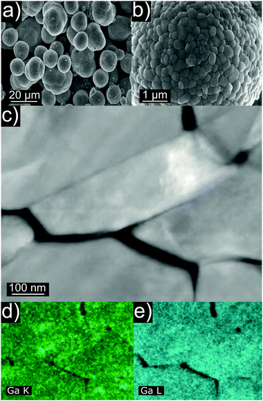
Ga-doped LNO samples were synthesized via a solid-state reaction route. We initially assumed the stoichiometry LiNi1−yGayO2 (0.00 ≤ y ≤ 0.05, where y = 0 is a LNO reference sample and 0.01 ≤ y ≤ 0.05 are LNO with 1 to 5% nominal molar substitution). In the first report on Ga doping, the authors proposed a wet mixing/vacuum-drying/calcination synthesis route with the best results obtained when using Ga(NO3)3·xH2O and calcining at 660 °C for 15 h.19 In other studies, Ga-doped LNO was synthesized using the combustion method with a pre-annealing step (as well using Ga(NO3)3·xH2O as Ga precursor).20–22 Here, we chose to wet-mix the precursors and pre-anneal them at 300 °C before calcination at 700 °C. The former step is known to promote hydroxide decomposition and an initial lithiation of the rock salt-type structure,25 while the latter represents an optimum temperature for synthesis of well-oxidized and well-crystallized LNO, avoiding excessive decomposition of the material.3,8Fig. 1a and b show representative SEM images of as-synthesized Ga-doped LNO. All samples, including the reference LNO, exhibit comparable secondary particle morphologies. Typically, the secondary particles are of spherical shape, the majority having diameters in the range between 6 and 9 μm. However, smaller spherical secondary particles and larger agglomerates (mostly in the size range of 10–14 μm) are present as well. The primary particles size is found to be quite variable, ranging between 100 and 600 nm. Fig. 1c depicts primary particles at higher magnification, as captured during STEM investigation of the pristine sample. Fig. 1d and e shows STEM-EDX images of the respective area. A nearly uniform Ga signal originating from the primary particles indicates the homogeneous distribution of Ga into the structure of LNO.
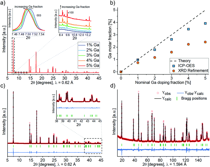
The crystal structure of all samples was investigated by synchrotron-based X-ray diffraction (Fig. 2a). The diffraction patterns vary only slightly between different samples, as can be seen from the insets in Fig. 2a. The angular shift of Bragg reflections towards smaller angles with increasing Ga content indicates firstly that doping was achieved and secondly that Ga enlarges the unit cell parameter of LNO. A small but increasing amount of the impurity phase Li5GaO4 (ICSD 9082) was observed with increasing amount of Ga precursor. Fig. 2b shows the total Ga content of the synthesized samples, which was determined by ICP-OES. According to ICP-OES, the nominal doping ranges from 0 to 4%, most likely due to an underestimated water content of the precursor Ga(NiO3)3·xH2O (despite the fact that x was determined by thermogravimetric analysis, see Fig. S1, ESI†). Furthermore, Fig. 2b includes the content of Ga ions in the Li layer (site occupancy factor of the 3b site), as determined by Rietveld refinement of XRD data (details of the refinement are discussed in the following). The actual Ga content was lower than the ICP-OES values, which can be mainly accounted for by the formation of the impurity phase Li5GaO4. While its presence was negligible in case of 1–2% nominal doping, Rietveld analysis of the powder XRD data yielded estimated fractions of Li5GaO4 of 0.5, 0.8 and 0.9 mol% in the samples with 3, 4 and 5% nominal doping, respectively. This indicates a limited solubility of Ga in the LNO phase (under the employed synthesis conditions). Moreover, while no particular trend was observed in the secondary or primary particles size by SEM/TEM with increasing Ga content, we noticed from the Rietveld refinement a decreasing apparent average crystal size (size of the coherent diffraction domains) ranging from 148 nm for reference LNO to 118 nm for 5% nominal doping (Fig. S2, ESI†).
Fig. 2c shows an example of the Rietveld analysis results, which are gathered in Table S1 (ESI†). The agreement of observed and calculated structural data is emphasized by the good fit of the respective patterns, even in the high-angle range (see inset in Fig. 2c). By Rietveld analysis of the synchrotron-based XRD data we determined the location of Ga3+ in the unit cell, i.e. whether it occupies the Ni or Li site. Unfortunately, there is very little contrast between Ga (Z = 31) and Ni (Z = 28), so the two elements can hardly be distinguished via X-rays. Similar considerations hold for the use of neutron diffraction if used alone [bcoh(Ni) = 10.3 barns, bcoh(Ga) = 7.29 barns]. For this reason, after the synchrotron-based XRD analysis of the full sample series, a combined refinement of both synchrotron and neutron diffraction datasets was performed (see Fig. 2c and d) for the 4%-Ga sample. A combined use of the two probes allows, in general, to draw more meaningful conclusions about the cations distribution in layered structures.26
Four different hypotheses concerning the placement of Ni and Ga ions in the 3b (Li layer) and/or the 3a (Ni layer) sites of the LNO structure (Table 1) have been evaluated. Due to the low off-stoichiometry in these samples, the presence of Li in the Ni layer was ruled out, which is supported by neutron diffraction studies available in the literature.27
| Cations in Li (3b) site | Cations in Ni (3a) site | |
|---|---|---|
| I | Li, Ga | Ni |
| II | Li | Ni, Ga |
| III | Li, Ni | Ni, Ga |
| IV | Li, Ga | Ni, Ga |
Hypotheses I, II and IV represent Ga substitution of Li, of Ni or both of them on their respective sites. Hypotheses III represents the typical off-stoichiometry of LNO, i.e., the presence of Ni cations in the Li layer, with Ga occupying the Ni layer. As of Rietveld refinement, hypothesis I, i.e., doping of the Li interlayer (3b sites), resulted in the best agreement with the experimental data. In particular, whenever trying to position Ga on the Ni site, the site occupancy factor of Ga turned negative, indicating that, if anything, a lower and not higher electronic density on the Ni site can favorably fit the data. As previously mentioned, XRD is not well suited to test the presence of Li in the Ni layer. Nonetheless, several studies have confirmed that this may occur only in samples that are highly off-stoichiometric, which is not the case for our samples. In conclusion, physically meaningful results were obtained in the refinement only with Ga occupying the Li site (hypothesis I, Li1−yGayNiO2), whereas for the other hypotheses either the occupation values of the Ni and/or Li site or the isotropic atomic displacement parameter Biso of Ni became negative. Thus, we consider in the following that Ga always occupies the Li site, although we cannot exclude with certainty that some amount of it could also occupy the Ni site. Table 2 summarizes the refinement results for the representative 4% nominal doping sample (Table S2 shows typical results for a case with an invalid structural hypothesis.).
| Li1−yGayNiO2 (4% nominal doping) | ||
R![[3 with combining macron]](https://www.rsc.org/images/entities/char_0033_0304.gif) m, Z = 3 m, Z = 3 |
X-rays | Neutrons |
| a = 2.87909(6) Å | R Bragg = 2.33% | R Bragg = 3.67% |
| c = 14.2167(2) Å | R wp = 9.44% | R wp = 12.2% |
| V = 102.056(3) Å3 | χ2 = 7.34 | |
| Atom | Wyckoff position | Atomic position | Occ | B iso | ||
|---|---|---|---|---|---|---|
| x/a | y/b | z/c | ||||
| O | 6c | 0 | 0 | 0.2583(2) | 1 | 0.81(5) |
| Ni | 3a | 0 | 0 | 0 | 1 | 0.35(1) |
| Li | 3b | 0 | 0 | 0.5 | 0.977(3) | 0.9(2) |
| Ga | 3b | 0 | 0 | 0.5 | 0.023(3) | 0.9(2) |
In summary, we found that the Ga3+ ion takes the role of off-stoichiometric Ni2+ which is usually found in the Li layer in LNO ([Li1−zNiz]NiO2). One should note that, as previously mentioned, the ionic size of Ga3+ is larger than the size of Ni3+ constituting the Ni layers, while it is smaller than the size of Ni2+ and Li+, usually occupying the Li interlayer. So both locations are equally likely. Moreover, Ga3+ is more effective than Ni2+ at reducing the average Ni oxidation state in the sample, thus facilitating its synthesis.
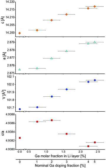
Fig. 3 shows the evolution of lattice parameters with increasing Ga content. Both a and c parameters increase upon Ga incorporation, as expected from the shift of the Bragg reflections (Fig. 2a). Consequently, the unit cell volume increases as well. This effect decreases as the Ga content gets higher, i.e., the relation is not linear over the investigated doping range. The c/a ratio fluctuates around the value of our reference LNO (4.9383), however, with small relative changes. An approximately constant ratio is also reported in the literature.4 This indicates that the extent of rhombohedral distortion is neither improved nor worsened by the presence of Ga, as opposed to other dopants such as Co that typically stabilize the layered structure of LNO (namely they increase the amount of rhombohedral distortion of the original cubic lattice).28
Fig. 4 shows the z-coordinate of the oxygen atom in LNO. A slight reduction of z can be noticed with increasing Ga fraction in the structure. The interlayer thickness I = c/3 − S (where c is the unit cell parameter and S represents the Ni layer thickness) decreases with increasing Ga content, which is consistent with Ga being inserted into the Li layer (due to the smaller ionic radius of Ga3+ compared to Li+). In contrast, the layer thickness S = c(2/3 − 2zox) increases, which can be explained by the partial reduction of Ni3+ to Ni2+ to maintain charge neutrality. As a trivalent Ga ion substitutes a monovalent Li ion, two Ni3+ ions are reduced to Ni2+ according to Li1−yGay[Ni3+1−2yNi2+2y]O2.
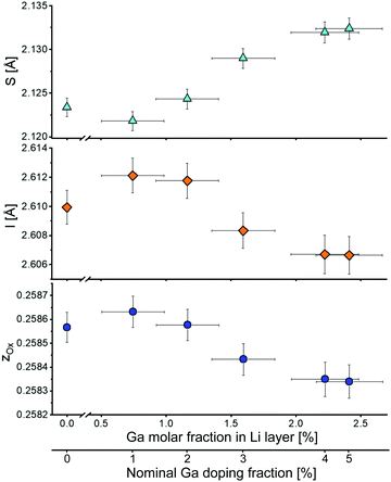 | ||
| Fig. 4 Layer thickness S, interlayer thickness I and z-coordinate of oxygen zox as a function of the Ga content in the Li layer. The bottom x-axis indicates the nominal Ga doping. | ||
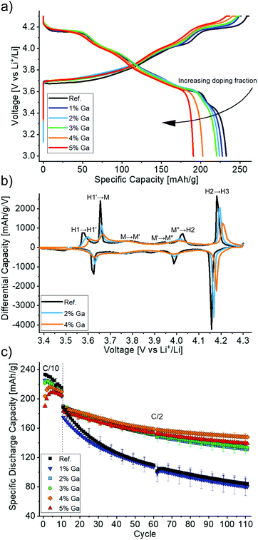
Then, the electrochemical performance of the Ga-doped LNO CAMs was tested. Fig. 5a shows the first cycle voltage profiles of the different samples. The initial specific charge and discharge capacities decreased with increasing Ga content, as expected due to the redox inactivity of gallium. However, the big differences between the initial capacities can partly be explained by the initial capacity activation period (i.e., the largest capacities are not reached in the first cycle), which may last for 2 to 5 cycles. This initial increase in capacity is more pronounced for 4 and 5% nominal doping and is presumably a surface-related phenomenon, which is beyond the scope of this work. Furthermore, the voltage profiles show less pronounced plateaus and more sloped curves for higher Ga contents. This suggests a more solid solution-like behavior caused by the doping, which is in line with findings in the literature.19,22
The trend towards solid solution-like behavior becomes even more apparent in the third cycle differential capacity plots (Fig. 5b). One can notice the typically observed sequence H1 → M → H2 → H3 (with H and M denoting hexagonal and monoclinic phases, respectively) with transitions at around 3.65, 4.0 and 4.2 V during charging. Additionally, H1 → H1′, M → M′ and M′ → M′′ represent transitions that were ascribed to Li vacancy ordering processes.8,9 As expected from the voltage plateaus in the charge/discharge curves above, all observed features are most pronounced for LNO. In contrast, the peak intensities are consistently diminished both in charge and discharge with increasing Ga content. Notably, the broad peaks between 3.75 and 3.80 V as well as between 3.87 and 3.95 V vs. Li+/Li (charge) in the monoclinic domain of the reference LNO sample were almost completely suppressed for the doped samples.
Interestingly, one may also note from Fig. 5b that the average voltage of most of the features is increased for higher Ga contents. This occurs both in charge and discharge, so it does not indicate an increased polarization but rather a true thermodynamic increase in the equilibrium (de)intercalation voltage. Such an effect has been already reported for doping with Al and related to the different nature of the Al–O bond as opposed to the transition metal–oxygen bond. In the former, a higher voltage is required to extract electrons from orbitals of mostly anionic character, thus strongly influencing the voltage curve.29–31 Of note, an increased polarization in Al-doped LNO (for 10–50% substitution of Ni) has been reported and related to hindered charge delocalization in the Ni layer.32 Here, we did not observe higher polarization for increased Ga contents.
LNO with a nominal Ga content of 4% (2.2% as determined by Rietveld refinement), exhibited the largest specific discharge capacities after 110 cycles with a retention of 78% (Fig. 5c). For all nominal doping levels, except 1% Ga, significantly improved cycling performance was achieved with respect to the reference LNO. The respective values for the other samples of the doping series ranged between 69 and 76% (compared to 45 and 46% for the reference LNO and the 1% nominal doping, respectively). It should be noted that our reference LNO was not prepared under “optimal” LNO synthesis conditions, but instead it underwent the same treatment steps (wet-mixing, pre-annealing) as the doped samples. It is apparent that the synthesis approach chosen here has adverse effects on the capacity retention of the LNO reference CAM. While its initial specific discharge capacity was high (230 mA h g−1), better capacity retention can well be achieved for undoped LNO.6
The 2.2% Ga doping of the best material is in line with the optimal doping levels for Ga reported in the literature.19,22 It appears that this optimum represents a compromise between structural stabilization and formation of impurity phases. However, the high retention of 95% after 100 cycles reported by Nishida et al.19 could not be reproduced. Of note, these values were obtained at a rate of about 0.19C with 8 h of CV charging at 4.3 V, which is a rather unpractical cycling protocol and presumably the reason for a capacity increase from initially 190 to 200 mA h g−1 in the 60th cycle.
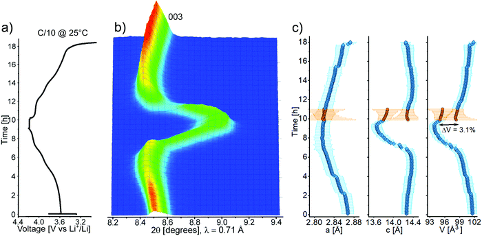
Operando XRD on the best-performing CAM was carried out to clarify the behavior of Ga-doped LNO during the (de)intercalation of lithium upon electrochemical cycling. This is the first operando investigation into Ga-doped LNO, for which thus far contradicting statements have been made. While Nishida et al.19 concluded that the phase transitions were fully suppressed based on ex situ XRD characterization (2 mol% Ga), Kwon et al.22 found the typical phase transitions known for LNO (from differential capacity plots for 2.5 mol% Ga). The main operando XRD results are presented in Fig. 6a–c. Interestingly, the recorded pattern sequence revealed that there is a marked difference in the material's structural transitions during charge and discharge. While a solid solution-like behavior, represented by the continuous shift in 003 reflection (Fig. 6b), takes place during Li deintercalation, the pattern sequence during Li intercalation indicates biphasic behavior. Fig. 6c shows that the unit cell volume undergoes a significant decrease during charging, which is typical of LNO and its derivatives.9 Initially, the contraction is determined by the steadily decreasing lattice parameter a (while c increases), before a rapid contraction occurs, driven by the sharp drop of c across the H2–H3 phase transition. By reducing the unit cell contraction during the H2–H3 transition from 5.7% (undoped)8 to 3.1% (doped), we confirm that Ga doping helps to decrease the mechanical strain arising upon cycling, which is known to cause fracture of both primary and secondary particles.6 However, the electrochemical data indicate that the structural problems of LNO are only partly alleviated.
To further investigate the causes of capacity fading, ex situ high-resolution STEM on pristine and cycled electrodes of the CAM showing the best capacity retention (4% nominal doping) was carried out (Fig. 7a–d). A manifestation of persisting mechanical instabilities are stacking faults in cycled LNO, which were already observed after two cycles (Fig. 7b). Moreover, the expected rock salt-like surface layer on the primary particles, with growing thickness upon cycling, was observed (Fig. 7c and d). This layer is reported to comprise a reduced rock salt-like phase, whose thickness can reach 20 nm after 100 cycles (for an upper cutoff voltage of 4.3 V), correlating with an increased impedance buildup.6
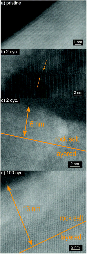 | ||
| Fig. 7 High-resolution STEM images of Ga-doped LNO (4% nominal doping). (a) Pristine electrode, (b and c) after 2 electrochemical cycles and (d) after 100 cycles. | ||
Taken together, the present study elucidates the effect that Ga doping has on LNO CAM, and it proves that Ga is an effective dopant, since relatively small fractions strongly influence the crystal structure, electrochemical performance and structural transitions during Li (de)intercalation. The incorporation of Ga in the Li layer is peculiar and comparable to the case of magnesium. Mg2+ ions only occupy Li sites (for doping levels <10%), suppress Ni off-stoichiometry and act as stabilizing “pillars” in the delithiated state of LNO due to their electrochemically inactive nature.14 Only 5% Mg in the Li layer is sufficient to cause complete solid solution behavior. Therefore, Mg doping decreases the specific capacity of LNO but significantly improves its cycling stability. The stabilizing effects that Ga has on the LNO structure during cycling may possibly be extended by further increasing the Ga content. However, with regard to the observed impurity phase formation, this will require the development of a tailored synthesis procedure. Moreover, it is clear from our data that while Ga is effective in improving some of LNO's instability issues, it is not able to stabilize its surface. In this respect, we believe a strategy that couples bulk doping with surface stabilization should be preferred to yield stable LNO-related compounds.33
Conclusions
In this study we revisited the Ga doping of LNO. Homogeneous doping on the atomic scale was demonstrated by STEM and synchrotron-based XRD. In contrast to previous reports, the dopant was found to be most likely localized in the Li layer of the host structure based on combined Rietveld refinement of synchrotron-based XRD and neutron diffraction data. As a consequence, the extent of the adverse off-stoichiometry of LNO, i.e., the presence of Ni ions in the interlayer, was reduced. Furthermore, with increasing dopant fraction, increasing lattice parameters, unit cell volume and layer thickness as well as decreasing interlayer distance ensued. While reducing the initial specific capacity, Ga incorporation improved the capacity retention over 110 cycles, with the best results at 2.2 mol% Ga doping, similar to previously reported optimal fractions. Operando XRD revealed an asymmetric behavior for the structural transition of the Ga-doped LNO between charge and discharge, indicating solid solution-like behavior during Li deintercalation (charge) and biphasic behavior for Li intercalation (discharge). The large overall volume change upon cycling was reduced by Ga doping, notably thanks to a smoother H2–H3 transition. Ex situ STEM analysis revealed that problems like mechanical instability and the formation of a surface rock salt layer still persist in Ga-doped LNO and are likely the main reasons for capacity fading. Overall, Ga is an effective dopant for LNO although its use alone is not sufficient to fully stabilize the material, which still requires further improvement, in particular of its surface properties.Conflicts of interest
There are no conflicts to declare.Acknowledgements
This study is part of the projects being supported by BASF SE. The work was partly performed with the support of the Karlsruhe Nano Micro Facility (KNMF), a Helmholtz Research Infrastructure at Karlsruhe Institute of Technology (KIT). We thank Dr. Thomas Bergfeldt (Institute for Applied Materials, IAM, KIT) for ICP-OES measurements.References
- D. Andre, S. J. Kim, P. Lamp, S. F. Lux, F. Maglia, O. Paschos and B. Stiaszny, J. Mater. Chem. A, 2015, 3, 6709–6732 RSC.
- J. R. Dahn and C. A. Michal, Solid State Ionics, 1990, 44, 87–97 CrossRef CAS.
- T. Ohzuku, A. Ueda and M. Nagayama, J. Electrochem. Soc., 1993, 140, 1862–1870 CrossRef CAS.
- M. Bianchini, M. Roca-Ayats, P. Hartmann, T. Brezesinski and J. Janek, Angew. Chem., Int. Ed., 2019, 58, 10434–10458 CrossRef CAS PubMed.
- A. Rougier, P. Gravereau and C. Delmas, J. Electrochem. Soc., 1996, 143, 1168–1175 CrossRef CAS.
- C. S. Yoon, D. W. Jun, S. T. Myung and Y. K. Sun, ACS Energy Lett., 2017, 2, 1150–1155 CrossRef CAS.
- M. Guilmard, C. Pouillerie, L. Croguennec and C. Delmas, Solid State Ionics, 2003, 160, 39–50 CrossRef CAS.
- H. Li, N. Zhang, J. Li and J. R. Dahn, J. Electrochem. Soc., 2018, 165, A2985–A2993 CrossRef CAS.
- L. de Biasi, A. Schiele, M. Roca-Ayats, G. Garcia, T. Brezesinski, P. Hartmann and J. Janek, ChemSusChem, 2019, 12, 2240–2250 CrossRef CAS PubMed.
- H. K. T. Ohzuku, A. Ueda, M. Nagayama and Y. Iwahoshi, Electrochim. Acta, 1993, 38, 1159–1167 CrossRef.
- E. Rossen, C. D. W. Jones and J. R. Dahn, Solid State Ionics, 1992, 57, 311–318 CrossRef CAS.
- M. Guilmard, A. Rougier, M. Grüne, L. Croguennec and C. Delmas, J. Power Sources, 2003, 115, 305–314 CrossRef CAS.
- H. Arai, M. Tsuda and Y. Sakurai, J. Power Sources, 2000, 90, 76–81 CrossRef CAS.
- C. Pouillerie, L. Croguennec, P. Biensan, P. Willmann and C. Delmas, J. Electrochem. Soc., 2000, 147, 2061–2069 CrossRef CAS.
- H. Li, M. Cormier, N. Zhang, J. Inglis, J. Li and J. R. Dahn, J. Electrochem. Soc., 2019, 166, A429–A439 CrossRef CAS.
- U. H. Kim, D. W. Jun, K. J. Park, Q. Zhang, P. Kaghazchi, D. Aurbach, D. T. Major, G. Goobes, M. Dixit, N. Leifer, C. M. Wang, P. Yan, D. Ahn, K. H. Kim, C. S. Yoon and Y. K. Sun, Energy Environ. Sci., 2018, 11, 1271–1279 RSC.
- H. H. Ryu, G. T. Park, C. S. Yoon and Y. K. Sun, J. Mater. Chem. A, 2019, 7, 18580–18588 RSC.
- C. S. Yoon, U. H. Kim, G. T. Park, S. J. Kim, K. H. Kim, J. Kim and Y. K. Sun, ACS Energy Lett., 2018, 3, 1634–1639 CrossRef CAS.
- Y. Nishida, K. Nakane and T. Satoh, J. Power Sources, 1997, 68, 561–564 CrossRef CAS.
- M. Y. Song, C. K. Park, S. Do Yoon, H. R. Park and D. R. Mumm, Ceram. Int., 2009, 35, 1145–1150 CrossRef CAS.
- M. Song, S. Kwon, I. Kwon and H. Park, J. Appl. Electrochem., 2007, 37, 421–427 CrossRef CAS.
- S. N. Kwon, D. R. Mumm, H. R. Park and M. Y. Song, J. Ceram. Process. Res., 2016, 17, 653–658 Search PubMed.
- R. D. Shannon, Acta Crystallogr., Sect. A: Cryst. Phys., Diffr., Theor. Gen. Crystallogr., 1976, 32, 751–767 CrossRef.
- F. Fauth, I. Peral, C. Popescu and M. Knapp, Powder Diffr., 2013, 28, S360–S370 CrossRef CAS.
- M. Bianchini, F. Fauth, P. Hartmann, T. Brezesinski and J. Janek, J. Mater. Chem. A, 2020, 8, 1808–1820 RSC.
- H. Liu, H. Liu, S. H. Lapidus, Y. S. Meng, P. J. Chupas and K. W. Chapmana, J. Electrochem. Soc., 2017, 164, A1802–A1811 CrossRef CAS.
- C. Pouillerie, E. Suard and C. Delmas, J. Solid State Chem., 2001, 158, 187–197 CrossRef CAS.
- D. Caurant, N. Baffier, B. Garcia and J. P. Pereira-Ramos, Solid State Ionics, 1996, 91, 45–54 CrossRef CAS.
- M. Aydinol, A. Kohan, G. Ceder, K. Cho and J. Joannopoulos, Phys. Rev. B: Condens. Matter Mater. Phys., 1997, 56, 1354–1365 CrossRef CAS.
- G. Ceder, Y. M. Chiang, D. R. Sadoway, M. K. Aydinol, Y. I. Jang and B. Huang, Nature, 1998, 392, 694–696 CrossRef CAS.
- Y. Il Jang, B. Huang, H. Wang, G. R. Maskaly, G. Ceder, D. R. Sadoway, Y. M. Chiang, H. Liu and H. Tamura, J. Power Sources, 1999, 81–82, 589–593 CrossRef.
- M. Guilmard, L. Croguennec, D. Denux and C. Delmas, Chem. Mater., 2003, 15, 4476–4483 CrossRef CAS.
- L. Mu, R. Zhang, W. H. Kan, Y. Zhang, L. Li, C. Kuai, B. Zydlewski, M. M. Rahman, C. J. Sun, S. Sainio, M. Avdeev, D. Nordlund, H. L. Xin and F. Lin, Chem. Mater., 2019, 31, 9769–9776 CrossRef CAS.
Footnote |
| † Electronic supplementary information (ESI) available. See DOI: 10.1039/d0ma00163e |
| This journal is © The Royal Society of Chemistry 2020 |

