Boosting the performance of sky-blue fluorescent OLEDs based on DPA-containing electron-transporting materials with a “V-shaped layout of triplet energy levels”
Shaofeng
Ye†
,
Runda
Guo†
,
Songpo
Xiang
,
Qing
Zhang
,
Xialei
Lv
,
Wei
Liu
,
Lianwei
Fan
,
Panpan
Leng
,
Shuaiqiang
Sun
and
Lei
Wang
 *
*
Wuhan National Laboratory for Optoelectronics, Huazhong University of Science and Technology, Wuhan, 430074, P. R. China. E-mail: wanglei@mail.hust.edu.cn
First published on 7th March 2019
Abstract
Here, using a strategy called “V-shaped layout of triplet energy levels (ETs)”, a high-T1, electron-deficient and bulky 1,5-diazarcarbazole (15NCz) was first introduced for the construction of new electron-transporting materials (ETMs). When 9,10-diphenylanthracene (DPA) was encapsulated by 15NCz at different positions, a series of ETMs with high electron mobility and good thermal stability were designed and synthesized: 9-(4-(9-([1,1′-biphenyl]-4-yl)anthracen-10-yl)phenyl)-9H-1,5-diazarcarbazole (p-S15NCzDPA), 9-(3-(9-([1,1′-biphenyl]-3-yl)anthracen-10-yl)phenyl)-9H-1,5-diazarcarbazole (m-S15NCzDPA), 9,10-bis(4-(9H-1,5-diazarcarbazole-9-yl)phenyl)anthracene (p-D15NCzDPA) and 9,10-bis(3-(9H-1,5-diazarcarbazole-9-yl)phenyl)anthracene (m-D15NCzDPA). When these novel ETMs were used in triplet–triplet fusion (TTF) fluorescent OLEDs, they exhibited superior performance compared to devices using the common ETMs TPBi and TmPyPB. In particular, devices based on m-S15NCzDPA and m-D15NCzDPA offered a maximum luminance (Lmax) of 66![[thin space (1/6-em)]](https://www.rsc.org/images/entities/char_2009.gif) 100 and 66
100 and 66![[thin space (1/6-em)]](https://www.rsc.org/images/entities/char_2009.gif) 950 cd m−2, maximum current efficiency (CEmax) of 17.40 and 17.20 cd A−1, and maximum power efficiency (PEmax) of 12.20 and 11.70 lm W−1 with a maximum external quantum efficiency (EQEmax) of 9.00% and 8.66%, respectively. More importantly, the device based on m-D15NCzDPA also achieved lower efficiency roll-offs at high luminance (roll-offs of 2.3% and 13.9% at 10
950 cd m−2, maximum current efficiency (CEmax) of 17.40 and 17.20 cd A−1, and maximum power efficiency (PEmax) of 12.20 and 11.70 lm W−1 with a maximum external quantum efficiency (EQEmax) of 9.00% and 8.66%, respectively. More importantly, the device based on m-D15NCzDPA also achieved lower efficiency roll-offs at high luminance (roll-offs of 2.3% and 13.9% at 10![[thin space (1/6-em)]](https://www.rsc.org/images/entities/char_2009.gif) 000 and 50
000 and 50![[thin space (1/6-em)]](https://www.rsc.org/images/entities/char_2009.gif) 000 cd m−2, respectively). This work demonstrated that a V-shaped layout of ETs strategy was beneficial for the construction of a series of high-performance ETMs.
000 cd m−2, respectively). This work demonstrated that a V-shaped layout of ETs strategy was beneficial for the construction of a series of high-performance ETMs.
1 Introduction
At present, organic light-emitting devices (OLEDs), as a new luminescent technology, have been commercialized in displays and lighting due to their outstanding features: vivid colors, wide viewing angles, flexibility, light weight and energy-saving properties.1–6 The light-emitting mechanism of OLEDs involves photon generation by recombination of holes and electrons in the emission zone.7–11 Charge carriers must be balanced in the emission zone to achieve high performance of devices.12–14 However, high-mobility electron-transporting materials (ETMs) are not common, which results in imbalanced electrons and holes within the emission zone and, thus, reduced device efficiency.To exploit novel ETMs with high electron mobility, various schemes have been proposed by many researchers: adopting intra-intermolecular hydrogen bonds; tuning energy levels by nitrogen orientation; manipulating the lowest unoccupied molecular orbital (LUMO) distribution of the molecule; relying on charge-exciton separation strategies; extending the π-conjugation of the molecule or utilizing a large coplanar π-conjugation system.15–25 The latter can increase electron mobility significantly. Conversely, ETMs with a high triplet energy (T1) could restrict carriers and excitons in the emission zone, but the degree of conjugation of the molecule is weakened, which may cause a low charge mobility.26 Therefore, exploiting new strategies for “ideal” ETMs to integrate charge-carrier transport and exciton-confinement properties has become particularly important.
For ideal commercial ETMs, a good electron injection, high electron mobility, high thermal stability and good exciton-confinement properties are essential. However, few ETMs can achieve such features simultaneously based. A series of pyridine-based ETMs were shown to possess inferior thermal stability because of their low glass transition temperature (Tg < 100 °C).17,27–29 Charge balance in a device with a terpyridine-based ETM could not be realized due to a low electron mobility (μe) in a study by Bian and colleagues.26 Recently, Duan and co-workers reported a series of anthracene-based ETMs: DPyPA, BPBiPA, DPPyA and BiPyA.22–25 These ETMs, with large π-conjugation anthracenes, possessed excellent electron injection, high μe (∼10−3 cm2 V−1 s−1), but low T1 (∼1.80 eV). The overall performance of OLEDs with these anthracene-based ETMs reached a good level, which profited from the charge-carrier balance in the emission zone.
Herein, a high T1 (2.83 eV), electron-deficient and bulky 15NCz with a C![[double bond, length as m-dash]](https://www.rsc.org/images/entities/char_e001.gif) N double bond as an electron-accepting moiety was first introduced for the construction of a series of ETMs.30 Meanwhile, DPA with low T1 (1.77 eV) was used as a rigid charge channel for fast transportation of electrons.31 The bulky 15NCzs were attached to the rigid planar π-conjugation core DPA. These ETMs were named 9-(4-(9-([1,1′-biphenyl]-4-yl)anthracen-9-yl)phenyl)-9H-1,5-diazarcarbazole (p-S15NCzDPA), 9-(3-(9-([1,1′-biphenyl]-3-yl)anthracen-10-yl)phenyl)-9H-1,5-diazarcarbazole (m-S15NCzDPA), 9,10-bis(4-(9H-1,5-diazarcarbazole-9-yl)phenyl)anthracene (p-D15NCzDPA) and 9,10-bis(3-(9H-1,5-diazarcarbazole-9-yl)phenyl)anthracene (m-D15NCzDPA), respectively. Through systematic characterization and analyses, it was found that the ETMs following a “V-shaped layout of ETs” strategy gained better material properties. These ETMs regulated LUMO deeper, and possessed higher electron mobility and better thermal stability. Finally, a series of sky-blue fluorescent OLEDs with TTF utilizing m-S15NCzDPA and m-D15NCzDPA as electron-transporting layers (ETLs) achieved excellent device performances: CEmax of 17.40 cd A−1, PEmax of 12.20 lm W−1 and EQEmax of 9.00% for the m-S15NCzDPA-based device with efficiency roll-off of 22.0% at luminance of 50
N double bond as an electron-accepting moiety was first introduced for the construction of a series of ETMs.30 Meanwhile, DPA with low T1 (1.77 eV) was used as a rigid charge channel for fast transportation of electrons.31 The bulky 15NCzs were attached to the rigid planar π-conjugation core DPA. These ETMs were named 9-(4-(9-([1,1′-biphenyl]-4-yl)anthracen-9-yl)phenyl)-9H-1,5-diazarcarbazole (p-S15NCzDPA), 9-(3-(9-([1,1′-biphenyl]-3-yl)anthracen-10-yl)phenyl)-9H-1,5-diazarcarbazole (m-S15NCzDPA), 9,10-bis(4-(9H-1,5-diazarcarbazole-9-yl)phenyl)anthracene (p-D15NCzDPA) and 9,10-bis(3-(9H-1,5-diazarcarbazole-9-yl)phenyl)anthracene (m-D15NCzDPA), respectively. Through systematic characterization and analyses, it was found that the ETMs following a “V-shaped layout of ETs” strategy gained better material properties. These ETMs regulated LUMO deeper, and possessed higher electron mobility and better thermal stability. Finally, a series of sky-blue fluorescent OLEDs with TTF utilizing m-S15NCzDPA and m-D15NCzDPA as electron-transporting layers (ETLs) achieved excellent device performances: CEmax of 17.40 cd A−1, PEmax of 12.20 lm W−1 and EQEmax of 9.00% for the m-S15NCzDPA-based device with efficiency roll-off of 22.0% at luminance of 50![[thin space (1/6-em)]](https://www.rsc.org/images/entities/char_2009.gif) 000 cd m−2; and CEmax of 17.20 cd A−1, PEmax of 11.70 lm W−1 and EQEmax of 8.66% for m-D15NCzDPA-based device with an efficiency roll-off of 13.9% at a luminance of 50
000 cd m−2; and CEmax of 17.20 cd A−1, PEmax of 11.70 lm W−1 and EQEmax of 8.66% for m-D15NCzDPA-based device with an efficiency roll-off of 13.9% at a luminance of 50![[thin space (1/6-em)]](https://www.rsc.org/images/entities/char_2009.gif) 000 cd m−2. Compared with commonly used ETMs (TPBi and TmPyPb), the overall performance of blue OLEDs was boosted by using ETMs with a V-shaped layout of ETs.
000 cd m−2. Compared with commonly used ETMs (TPBi and TmPyPb), the overall performance of blue OLEDs was boosted by using ETMs with a V-shaped layout of ETs.
2 Results and discussion
2.1 Synthesis and characterization
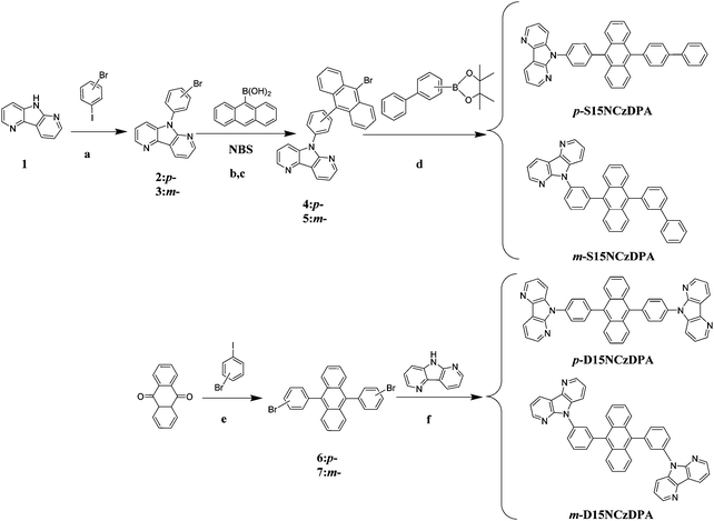
The specific synthetic route and molecular structure of this series of ETMs are depicted in Scheme 1. Intermediate compounds 1, 2, 3, 6 and 7 were synthesized according to the literature.30,32 These ETMs were synthesized further through a Suzuki cross-coupling reaction and Ullmann coupling reaction. Synthetic details are presented in the Experimental section. After the crude products had been purified preliminarily by recrystallization and silica-gel column chromatography, these ETMs were purified further by sublimation under vacuum for subsequent characterization of material properties and device fabrication. The photophysical properties of these ETMs were investigated by UV-Vis absorption spectroscopy, fluorescence spectroscopy, low-temperature phosphorescence spectroscopy, cyclic voltammetry (CV), differential scanning calorimetry (DSC) and thermal gravimetric analyses (TGA). The details of measurements are shown the work of Zhang and colleagues.332.2 Theoretical simulation
The optimized geometric structure in the ground state and electron-cloud distributions of the highest occupied molecular orbital (HOMO) and the LUMO of p-S15NCzDPA, m-S15NCzDPA, p-D15NCzDPA and m-D15NCzDPA were calculated by employing density functional theory (DFT) (Table 1).30 The peripheral 15NCzs enhanced the degree of molecular distortion. The highly twisted structures of these ETMs contributed to good thermal stability.24 The HOMO and LUMO of these ETMs were located mainly at the core anthracenes, suggesting that the latter were the main electronically active cores for these ETMs, which were mainly responsible for the fast transport of holes and electrons. The electron-deficient 15NCz with a nitrogen atom of the heteroaromatic ring as an electron-accepting moiety could deepen the LUMO energy levels of these ETMs, which contributed to the charge injection. A low T1 of ∼1.73 eV was calculated based on time-dependent DFT (TD-DFT) calculations; this low value was ascribed to the large π-conjugation contribution of the anthracenes, and corresponded to previous values reported for anthracenes.23,252.3 Thermal stability
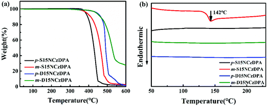
The thermal stability of p-S15NCzDPA, m-S15NCzDPA, p-D15NCzDPA and m-D15NCzDPA was measured by TGA (Fig. 1a) and DSC (Fig. 1b). A high decomposition temperature (Td, corresponding to 5% weight loss) of 382, 391, 442 and 440 °C for p-S15NCzDPA, m-S15NCzDPA, p-D15NCzDPA and m-D15NCzDPA, respectively, was recorded. The Tg of m-S15NCzDPA was 142 °C, but an obvious Tg was not observed for the other three compounds. The high Tg was a consequence of anthracene and 15NCz with rigid structures. This setup aided maintenance of the morphological stability of amorphous films upon thermal evaporation and helped to improve the overall stability of the device.2.4 Photophysical properties
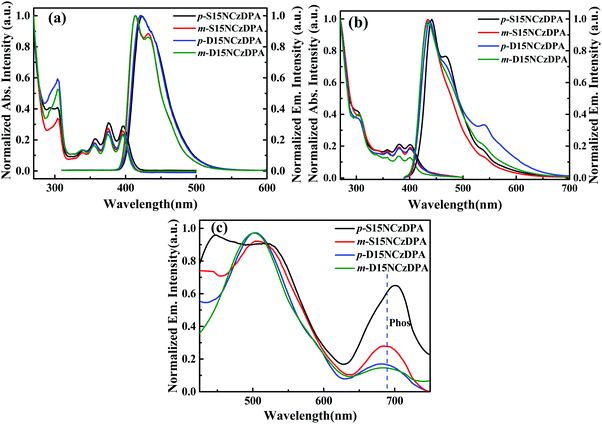
Fig. 2a and b describe the UV-visible absorption and fluorescence spectra of p-S15NCzDPA, m-S15NCzDPA, p-D15NCzDPA and m-D15NCzDPA in CH2Cl2 solution and neat film. In solution, there were three absorption peaks at 356, 376, 396 nm (Table 2), which originated from the π–π* transition of the core anthracenes.23 Another absorption peak at ∼305 nm originated from the π–π* transition of peripheral 15NCz.30 According to the onset of absorption of these ETMs, the energy gap (Eg) was ∼3.0 eV. The twisted structures of these ETMs restrained the formation of π–π stacking, so the absorption peaks in the film state had a negligible bathochromic shift. The fluorescence emission peak of these ETMs in CH2Cl2 was observed at ∼420 nm, and the films exhibited a bathochromic shift of the emission peak of ∼20 nm, which could be ascribed to the appropriate intermolecular π–π interaction. There were new peaks in the emission spectra of p-S15NCzDPA and p-D15NCzDPA. This phenomenon was attributed to excimer formation due to the interactions of peripheral 15NCzs.32 The low-temperature phosphorescence spectra (Fig. 2c) was measured in 2-methyl-tetrahydrofuran at 77 K. The phosphorescence emission peak of these ETMs was ∼690 nm. The T1 of these ETMs was estimated to be ∼1.80 eV, which is consistent with the T1 of the reported anthracene derivatives.23,25| ETM | λ abs (nm) solutiona | λ em (nm) solutiona | E g , (eV) | HOMO/LUMOe (eV) | HOMO/LUMOd (eV) | E T , (eV) | T g /T d (°C) |
|---|---|---|---|---|---|---|---|
| Filmb | Filmb | ||||||
| a Measured in CH2Cl2 solvent. b Measured in neat film. c Calculated by the onset of absorption. d HOMOs and LUMOs were measured by CV, Eg = LUMO–HOMO. e Calculated by Gaussian 09 at the B3LYP/6-31G(d) level. f Calculated by low-temperature phosphorescence spectroscopy. g Measured by DSC and TGA, respectively. N.A.: not available. | |||||||
| p-S15NCzDPA | 305/356/376/396 | 423 | 3.01/3.07 | −5.18/−1.69 | −5.63/−2.56 | 1.73/1.77 | N.A./382 |
| 303/358/380/402 | 442/468 | ||||||
| m-S15NCzDPA | 305/356/376/396 | 414/432 | 3.02/3.07 | −5.12/−1.66 | −5.62/−2.55 | 1.72/1.80 | 142/391 |
| 305/358/380/402 | 434 | ||||||
| p-D15NCzDPA | 305/356/376/396 | 422 | 3.01/2.97 | −5.26/−1.76 | −5.65/−2.68 | 1.73/1.82 | N.A./442 |
| 305/358/380/402 | 438/541 | ||||||
| m-D15NCzDPA | 305/356/376/396 | 414/432 | 3.02/2.99 | −5.33/−1.84 | −5.68/−2.69 | 1.73/1.81 | N.A./440 |
| 305/358/380/402 | 435 | ||||||
2.5 Electrochemical properties
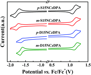
The electrochemical behaviors of p-S15NCzDPA, m-S15NCzDPA, p-D15NCzDPA and m-D15NCzDPA were evaluated by CV measurements in anhydrous CH2Cl2 and deoxidized DMF (N,N-dimethylformamide) solutions with 0.1 M tetrabutylammonium hexafluorophosphate (n-Bu4NPF6) as the electrolyte. All of these ETMs exhibited reversible oxidation and reduction waves in electrolyte solutions (Fig. 3), which suggested that these ETMs possessed good electrochemical stability. The measured HOMO/LUMO energy levels (in eV) of p-S15NCzDPA, m-S15NCzDPA, p-D15NCzDPA and m-D15NCzDPA were −5.63/−2.56, −5.62/−2.55, −5.65/−2.68 and −5.68/−2.69 eV, respectively, which was in agreement with the tendency of theoretical calculations. Results showed these 15NCz-containing ETMs could regulate the LUMO energy level appropriately. In particular, m-D15NCzDPA with a deeper LUMO energy level could better improve electron injection and promote charge-carrier balance.2.6 Electron-transporting properties
The time-of-flight (TOF) method was adopted to study the intrinsic electron-transporting characteristics of p-S15NCzDPA, m-S15NCzDPA, p-D15NCzDPA and m-D15NCzDPA. The device structure was ITO/ETMs (3–5 μm)/Al (100 nm), and the details of the experiment and calculation process can be seen in the work of Jin and colleagues.34 The typical TOF transients of electrons for these ETMs under an applied field are shown in Fig. 4. The electron mobilities of these ETMs were obtained by calculating, fitting and analyzing (Fig. 5). The electron mobilities of all these ETMs followed the Poole–Frenkel relationship. The Poole–Frenkel slopes for these ETMs were all negative, suggesting that the evaporated film of these ETMs would exhibit excellent thermal stability and help to prolong the lifetime of devices.23 Notably, the high electron mobility (in cm2 V−1 s−1) of m-D15NCzDPA lay in the range 5.2 × 10⁻³ to 2.6 × 10⁻³ in an electric field (in V cm−1) between 2.2 × 10⁵ and 4.6 × 10⁵. Compared with the widely used anthracene derivatives TmPyPB and TPBi, the electron mobility of these newly designed ETMs was high.17,25 The high electron-transporting mobility of these ETMs aided realization of charge-carrier balance and reduction of operating voltages, which improved the overall efficiency of the devices.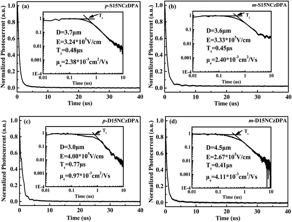 | ||
| Fig. 4 Typical time-of-flight (TOF) transients of electrons for (a) p-S15NCzDPA, (b) m-S15NCzDPA, (c) p-D15NCzDPA and (d) m-D15NCzDPA under an applied field. | ||
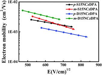 | ||
| Fig. 5 Electron mobility vs. square root of the electric field for p-S15NCzDPA, m-S15NCzDPA, p-D15NCzDPA and m-D15NCzDPA. | ||
2.7 Electroluminescence properties
We examined the electroluminescence properties of all ETMs-based OLEDs using different structures: ITO/HATCN (10 nm)/TAPC (40 nm)/TCTA (5 nm)/MADN: 3% BUBD-1 (20 nm)/ETL (30 nm)/LiQ (1 nm)/Al (70 nm). The details of device fabrication and measurements can be seen in the work of Xiang and co-workers.35 OLED structures with different ETMs and the molecular structures adopted are displayed in Fig. 6. Hexaazatriphenylenehexacabonitrile (HATCN), di-(4-(N,N-ditolyl-amino)phenyl)cyclohexane (TAPC), N,N,N-tris(4-(9-carbazolyl)phenyl)amine (TCTA), 2-methyl-9,10-di(2-naphthyl)anthracene (MADN), and BUBD-1 were used as the hole-injecting material, hole-transporting material, electron-blocking material, host material with TTF, and sky-blue fluorescence dopant, respectively.36,37p-S15NCzDPA, m-S15NCzDPA, p-D15NC-zDPA and m-D15NCzDPA were adopted as ETMs to fabricate devices A, B, C, and D, respectively. For comparison, device E and device F, with the commonly used ETMs TPBi and TmPyPB, were fabricated, respectively.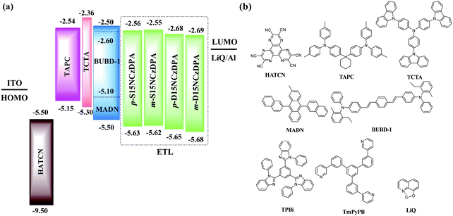 | ||
| Fig. 6 (a) Structures of OLEDs with novel ETMs. (b) Molecular structures of the compounds used in these OLEDs. | ||
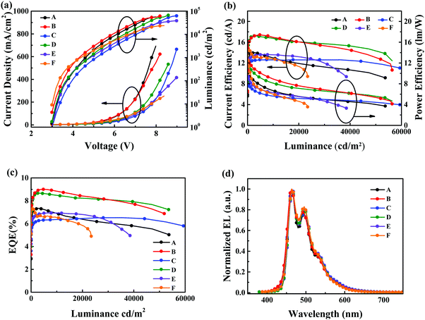
Fig. 7 shows the current density–voltage–luminance (J–V–L) curves, current efficiency–luminance–power efficiency curves, EQE curves and normalized EL spectra of these devices. The device-performance parameters are displayed in Table 3. The normalized EL spectra of all devices are depicted in Fig. 7d. All of these devices showed emission from the sky-blue fluorescence dopant BUBD-1 with Commission International de L’eclairage (CIE) coordinates of (0.16, 0.30).36 Devices B and D showed better performance with relatively low operating voltages of 3.1 and 3.2 V at a luminance of 10 cd m−2, Lmax of 66![[thin space (1/6-em)]](https://www.rsc.org/images/entities/char_2009.gif) 100 and 66
100 and 66![[thin space (1/6-em)]](https://www.rsc.org/images/entities/char_2009.gif) 950 cd m−2 at operating voltages of 8.4 and 8.6 V, CEmax of 17.40 and 17.20 cd A−1, PEmax of 12.20 and 11.70 lm W−1, and EQEmax of 9.00% and 8.66%, respectively. Devices B and D featuring m-S15NCzDPA and m-D15NCzDPA achieved the optimal device performance because the higher electron mobility of m-S15NCzDPA and m-D15NCzDPA facilitated carrier balance in the emission zone. Compared with devices C and D, devices A and B displayed slightly inferior efficiency roll-off (Fig. 7b and c), which could be attributed to greater triplet quenching. In principle, as the triplet exciton concentration increased at a high operating voltage, the diffusion probability of excitons also increased. ETMs with a low T1 could not restrict excitons in the emission zone, and induced exciton quenching in ETMs. When these ETMs with a V-shaped layout of ETs were constituted, the high-T1, large, spatially peripheral 15NCz could stop the triplet excitons from being quenched. Meanwhile, the difference in efficiency roll-off of devices A and B with asymmetrical ETMs and in devices C and D with symmetrical ETMs could demonstrate the spatial effect of high-T1 peripheral groups.23 That is, ETMs with a higher electron mobility and large spatial effect of high-T1 peripheral groups had a major impact on the performance of devices with low efficiency roll-off. For reference devices E and F, the device performances of TPBi and TmPyPb were inferior to the ETMs that we designed. The low electron mobility of TPBi and low Tg of TmPyPB were disadvantageous to the preparation of high-performance devices. In summary, the high electron mobility, high thermal stability and exciton-blocking effect of these ETMs were used to realize the high performance of sky-blue fluorescent OLEDs with TTF, thereby confirming the potential application of these ETMs with a V-shaped layout of ETs.
950 cd m−2 at operating voltages of 8.4 and 8.6 V, CEmax of 17.40 and 17.20 cd A−1, PEmax of 12.20 and 11.70 lm W−1, and EQEmax of 9.00% and 8.66%, respectively. Devices B and D featuring m-S15NCzDPA and m-D15NCzDPA achieved the optimal device performance because the higher electron mobility of m-S15NCzDPA and m-D15NCzDPA facilitated carrier balance in the emission zone. Compared with devices C and D, devices A and B displayed slightly inferior efficiency roll-off (Fig. 7b and c), which could be attributed to greater triplet quenching. In principle, as the triplet exciton concentration increased at a high operating voltage, the diffusion probability of excitons also increased. ETMs with a low T1 could not restrict excitons in the emission zone, and induced exciton quenching in ETMs. When these ETMs with a V-shaped layout of ETs were constituted, the high-T1, large, spatially peripheral 15NCz could stop the triplet excitons from being quenched. Meanwhile, the difference in efficiency roll-off of devices A and B with asymmetrical ETMs and in devices C and D with symmetrical ETMs could demonstrate the spatial effect of high-T1 peripheral groups.23 That is, ETMs with a higher electron mobility and large spatial effect of high-T1 peripheral groups had a major impact on the performance of devices with low efficiency roll-off. For reference devices E and F, the device performances of TPBi and TmPyPb were inferior to the ETMs that we designed. The low electron mobility of TPBi and low Tg of TmPyPB were disadvantageous to the preparation of high-performance devices. In summary, the high electron mobility, high thermal stability and exciton-blocking effect of these ETMs were used to realize the high performance of sky-blue fluorescent OLEDs with TTF, thereby confirming the potential application of these ETMs with a V-shaped layout of ETs.
| Device | Voltagea (V) | L max/voltageb (cd m−2)/(V) | CEc (cd A−1) | PEc (lm W−1) | EQEc (%) | CIE (x, y)d |
|---|---|---|---|---|---|---|
a Operating voltage (L = 10 cd m−2).
b Voltage at Lmax.
c Order of CEs, PEs and EQEs at maximum values, luminance of 10![[thin space (1/6-em)]](https://www.rsc.org/images/entities/char_2009.gif) 000 and 50 000 and 50![[thin space (1/6-em)]](https://www.rsc.org/images/entities/char_2009.gif) 000 cd m−2, respectively.
d CIE coordinates at 20 mA cm−2. 000 cd m−2, respectively.
d CIE coordinates at 20 mA cm−2.
|
||||||
| A | 3.2 | 55![[thin space (1/6-em)]](https://www.rsc.org/images/entities/char_2009.gif) 820/8.0 820/8.0 |
13.96/12.97/9.75 | 9.43/6.57/3.94 | 7.33/7.00/5.31 | (0.17, 0.28) |
| B | 3.1 | 66![[thin space (1/6-em)]](https://www.rsc.org/images/entities/char_2009.gif) 100/8.4 100/8.4 |
17.40/17.00/13.02 | 12.20/8.87/5.26 | 9.00/8.80/7.02 | (0.16, 0.28) |
| C | 3.3 | 68![[thin space (1/6-em)]](https://www.rsc.org/images/entities/char_2009.gif) 470/8.8 470/8.8 |
13.10/12.72/11.85 | 8.85/5.55/4.38 | 6.59/6.34/6.24 | (0.18, 0.30) |
| D | 3.2 | 66![[thin space (1/6-em)]](https://www.rsc.org/images/entities/char_2009.gif) 950/8.6 950/8.6 |
17.20/16.70/14.34 | 11.70/8.04/5.55 | 8.66/8.46/7.46 | (0.16, 0.30) |
| E | 3.2 | 38![[thin space (1/6-em)]](https://www.rsc.org/images/entities/char_2009.gif) 630/9.0 630/9.0 |
13.58/13.56/— | 9.74/6.23/— | 6.92/6.90/— | (0.16, 0.29) |
| F | 3.0 | 23![[thin space (1/6-em)]](https://www.rsc.org/images/entities/char_2009.gif) 500/8.4 500/8.4 |
14.46/12.73/— | 12.51/5.79/— | 7.32/6.53/— | (0.16, 0.29) |
3 Conclusions
We presented and demonstrated the novel structure strategy of a V-shaped layout of ETs for ETMs. The high-T115NCz, as an electron-deficient and bulky group, was first introduced as a peripheral group to protect the core DPA. These ETMs exhibited high mobility, high thermal stability and good exciton-confinement characteristics, simultaneously. The m-D15NCzDPA-based sky-blue TTF fluorescent OLED achieved optimal device performance, with CEmax, PEmax and EQEmax of 17.20 cd A−1, 11.70 lm W−1, and 8.66%, respectively, and low efficiency roll-off at high luminance (13.9% at 50![[thin space (1/6-em)]](https://www.rsc.org/images/entities/char_2009.gif) 000 cd m−2). The reduced efficiency roll-off could be attributed to exciton confinement originating from the V-shaped layout of ETs strategy. This work has broadened the material design and applications of ETMs and could pave the way for developing high-performance blue OLEDs.
000 cd m−2). The reduced efficiency roll-off could be attributed to exciton confinement originating from the V-shaped layout of ETs strategy. This work has broadened the material design and applications of ETMs and could pave the way for developing high-performance blue OLEDs.
4 Experimental section
All new intermediates and final products were demonstrated by 1H NMR, 13C NMR, mass spectroscopy and elemental analyses.Synthesis of 9-(4-(10-bromoanthracen-9-yl)phenyl)-9H-1,5-diazarcarbazole (compound 4)
Under a N2 atmosphere, compound 2 (1.5 g, 4.6 mmol), 9-anthraceneboronic acid (1.1 g, 5.1 mmol), Pd(PPh3)4 (0.1 g, 0.1 mmol), toluene (50 ml), K2CO3 aqueous solution (2.0 M, 25 ml) and ethanol (25 ml) were mixed together. The reaction system was refluxed for 24 h at 110 °C. After the mixture had been extracted with CH2Cl2, the extract was dried with anhydrous MgSO4. Then, the solid phase was removed by negative-pressure filtration, and the organic phase was removed by vacuum-rotary evaporation. A solid powder with few impurities was purified preliminarily by silica-gel column chromatography to obtain a white intermediate product. The latter (2.1 g, 5.0 mmol), N-bromosuccinimide (NBS) (0.9 g, 5.5 mmol) and CHCl3 (50 ml) were mixed together. Under a N2 atmosphere, the reaction system was refluxed for 6 h at 70 °C. The organic phase was removed by vacuum-rotary evaporation. A solid powder with few impurities was purified preliminarily by silica-gel column chromatography to obtain a yellow compound 4 (2.1 g, 84%). 1H NMR (400 MHz, CDCl3) δ [ppm]: 8.87–8.85 (d, J = 8.0 Hz, 1H), 8.72–8.70 (d, J = 4.8 Hz, 2H), 8.65–8.61 (t, J = 6.4 Hz, 2H), 8.12–8.10 (d, J = 8.0 Hz, 1H), 7.92–7.86 (t, J = 15.2 Hz, 2H), 7.81–7.79 (d, J = 8.8 Hz, 2H), 7.68–7.60 (m, 4H), 7.52–7.35 (m, 4H). MS (MALDI-TOF): calculated for C30H18BrN3, 500.40; found 500.14, [M]+.Synthesis of 9-(3-(10-bromoanthracen-9-yl)phenyl)-9H-1,5-diazarcarbazole (compound 5)
According to the synthetic method of compound 4, a similar synthetic method was used to prepare compound 5 (1.8 g, 76%). 1H NMR (400 MHz, CDCl3) δ [ppm]: 8.76–8.74 (d, J = 7.6 Hz, 1H), 8.64–8.60 (m, 4H), 7.96–7.91 (m, 2H), 7.87–7.83 (m, 3H), 7.70–7.69 (t, J = 2.0 Hz, 1H), 7.62–7.58 (m, 2H), 7.54–7.52 (m, 1H), 7.47–7.42 (m, 2H), 7.38–7.32 (m, 2H). MS (MALDI-TOF): calculated for C30H18BrN3, 500.40; found 499.14, [M]+.Synthesis of 9-(4-(9-([1,1′-biphenyl]-4-yl)anthracen-10-yl)phenyl)-9H-1,5-diazarcarbazole (p-S15NCzDPA)
Under a N2 atmosphere, compound 4 (3.0 g, 6.0 mmol), 4-biphenylboronic acid (1.4 g, 7.2 mmol), Pd(PPh3)4 (0.1 g, 0.1 mmol), toluene (60 ml), K2CO3 aqueous solution (2.0 M, 30 ml) and ethanol (30 ml) were mixed together. The reaction system was refluxed for 24 h at 110 °C. The mixture was extracted with CH2Cl2. The organic phase was dried with anhydrous MgSO4, then the solid phase was removed by negative-pressure filtration. The organic phase was removed by vacuum-rotary evaporation. A solid powder with few impurities was purified preliminarily by silica-gel column chromatography to obtain the yellow target product p-S15NCzDPA (2.5 g, 73%). 1H NMR (400 MHz, CDCl3) δ [ppm]: 8.79–8.76 (dd, J = 1.6 Hz, 1H), 8.72–8.71 (dd, J = 1.2 Hz, 2H), 8.10–8.07 (dd, J = 1.6, 1.2 Hz, 1H), 7.94–7.92 (d, J = 8.4 Hz, 2H), 7.88–7.75 (m, 10H), 7.58–7.47 (m, 5H), 7.42–7.36 (m, 6H). 13C NMR (100 MHz, CDCl3) δ [ppm]: 152.16, 148.63, 143.69, 140.84, 140.37, 140.06, 138.59, 137.94, 137.26, 136.01, 134.92, 133.93, 132.78, 131.77, 129.96, 129.53, 128.94, 127.49, 127.20, 127.16, 127.13, 126.96, 126.73, 125.35, 125.22, 124.82, 121.36, 117.89, 117.33, 115.85. MS (MALDI-TOF): calculated for C42H27N3, 573.22; found 573.84, [M]+; elemental analysis calculated (%) C42H27N3: C 87.94, H 4.75, N 7.31; C 87.95, H 4.73, N 7.32.Synthesis of 9-(3-(9-([1,1′-biphenyl]-3-yl)anthracen-10-yl)phenyl)-9H-1,5-diazarcarbazole (m-S15NCzDPA)
According to the synthetic method of p-S15NCzDPA, a similar synthetic method was used to prepare m-S15NCzDPA (2.2 g, 64%). 1H NMR (600 MHz, CDCl3) δ [ppm]: 8.73–8.71 (d, J = 7.2 Hz, 1H), 8.66–8.65 (m, 1H), 8.63–8.62 (m, 1H), 7.97–7.95 (t, J = 6.6 Hz, 2H), 7.91–7.87 (dd, J = 8.4, 7.8 Hz, 3H), 7.79–7.77 (m, 4H), 7.75–7.65 (m, 4H), 7.63–7.61 (dd, J = 4.2 Hz, 1H), 7.48–7.40 (m, 5H), 7.38–7.31 (m, 5H). 13C NMR (100 MHz, CDCl3) δ [ppm]: 151.09, 147.58, 142.53, 140.24, 139.75, 139.71, 139.65, 139.03, 138.37, 136.52, 134.76, 134.72, 132.67, 129.62, 129.60, 129.19, 128.93, 128.90, 128.85, 128.37, 128.21, 128.19, 127.90, 127.83, 127.81, 126.46, 126.20, 126.17, 126.14, 125.72, 125.23, 125.14, 124.46, 124.22, 120.26, 116.64, 116.27, 114.68. MS (MALDI-TOF): calculated for C42H27N3, 573.22; found 574.36, [M]+; elemental analysis calculated (%) C42H27N3: C 87.94, H 4.75, N 7.31; C 87.92, H 4.72, N 7.35.Synthesis of 9,10-bis(4-(9H-1,5-diazarcarbazole-9-yl)phenyl)anthracene (p-D15NCzDPA)
Under a N2 atmosphere, compound 1 (15NCz) (1.5 g, 8.9 mmol), compound 6 (2.1 g, 4.2 mmol), CuI (0.16 g, 0.85 mmol), K2CO3 (2.9 g, 21.1 mmol) and 18-crown-6 (0.2 g, 0.8 mmol) were dissolved in 1,3-dimethyl-3,4,5,6-tetrahydro-2(1H)-pyrimidinone (DMPU, 5 ml) and stirred for 24 h at 180 °C. After the mixture had been washed using water, the solid phase was collected by negative-pressure filtration, A solid powder with few impurities was purified preliminarily by recrystallization and silica-gel column chromatography to obtain the yellow target product p-D15NCzDPA (2.0 g, 72%). 1H NMR (400 MHz, CDCl3) δ [ppm]: 8.81–8.79 (d, J = 7.2 Hz, 2H), 8.72–8.71 (d, J = 4.4 Hz, 4H), 8.11–8.09 (d, J = 8.0 Hz, 2H), 7.99–7.88 (m, 8H), 7.79–7.77 (d, J = 8.4 Hz, 4H), 7.52–7.49 (m, 2H), 7.45–7.41 (m, 6H). 13C NMR (100 MHz, CDCl3) δ [ppm]: 152.17, 148.73, 136.42, 132.76, 129.98, 126.77, 125.45, 121.38. MS (MALDI-TOF): calculated for C46H28N6, 664.24; found 664.52, [M]+; elemental analysis calculated (%) C46H28N6: C 83.12, H 4.26, N 12.62; C 83.13, H 4.26, N 12.61.Synthesis of 9,10-bis(3-(9H-1,5-diazarcarbazole-9-yl)phenyl)anthracene (m-D15NCzDPA)
According to the synthetic method of p-D15NCzDPA, a similar synthetic method was used to prepare m-D15NCzDPA (1.8 g, 65%). 1H NMR (400 MHz, CDCl3) δ [ppm]: 8.75–8.71 (t, J = 6.8 Hz, 2H), 8.66–8.60 (m, 4H), 8.04–7.85 (m, 10H), 7.78–7.75 (d, J = 15.2 Hz, 2H), 7.63–7.57 (dd, J = 7.6 Hz, 2H), 7.45–7.34 (m, 8H). 13C NMR (100 MHz, CDCl3) δ [ppm]: 152.11, 152.08, 148.64, 148.62, 143.52, 143.51, 140.49, 140.01, 139.99, 136.23, 135.80, 133.67, 133.64, 130.57, 130.00, 129.88, 129.44, 129.43, 129.19, 129.16, 126.91, 126.22, 125.58, 121.29, 121.26, 117.68, 117.66, 117.34, 117.33, 115.67, 115.66. MS (MALDI-TOF): calculated for C46H28N6, 664.24; found 664.17, [M]+; elemental analysis calculated (%) C46H28N6: C 83.12, H 4.26, N 12.62; C 83.15, H 4.23, N 12.62.Conflicts of interest
There are no conflicts to declare.Acknowledgements
This research work was supported by the NSFC/China (51573065, 51727809), China Postdoctoral Science Foundation (2017M620321), Science and Technology Support Program of Hubei Province (2015BAA075) and Fundamental Research Funds for the Central Universities, HUST (2018KFYXKJC043). We thank SCTS/CGCL HPCC of HUST for providing computing resources and technical support. The Analytical and Testing Center at Huazhong University of Science and Technology is acknowledged for the characterization of new compounds.Notes and references
- H. G. Kim, K. H. Kim and J. J. Kim, Adv. Mater., 2017, 29, 1702159 CrossRef PubMed.
- D. Zhang, X. Song, M. Cai, H. Kaji and L. Duan, Adv. Mater., 2018, 30, 1705406 CrossRef PubMed.
- T. L. Wu, M. J. Huang, C. C. Lin, P. Y. Huang, T. Y. Chou, R. W. Chen Cheng, H. W. Lin, R. S. Liu and C. H. Cheng, Nat. Photonics, 2018, 12, 235–240 CrossRef CAS.
- Y. Sun, N. C. Giebink, H. Kanno, B. Ma, M. E. Thompson and S. R. Forrest, Nature, 2006, 440, 908–912 CrossRef CAS PubMed.
- Z. Yan, Y. Wang, J. Ding, Y. Wang and L. Wang, ACS Appl. Mater. Interfaces, 2018, 10, 1888–1896 CrossRef CAS PubMed.
- H. Fukagawa, T. Oono, Y. Iwasaki, T. Hatakeyama and T. Shimizu, Mater. Chem. Front., 2018, 2, 704–709 RSC.
- Q. Zhang, B. Li, S. Huang, H. Nomura, H. Tanaka and C. Adachi, Nat. Photonics, 2014, 8, 326–332 CrossRef CAS.
- K. H. Kim, S. Lee, C. K. Moon, S. Y. Kim, Y. S. Park, J. H. Lee, J. W. Lee, J. Huh, Y. You and J. J. Kim, Nat. Commun., 2014, 5, 4769 CrossRef CAS PubMed.
- J. Li, R. Zhang, Z. Wang, B. Zhao, J. Xie, F. Zhang, H. Wang and K. Guo, Adv. Opt. Mater., 2018, 6, 1701256 CrossRef.
- S. Lee, H. Shin and J. J. Kim, Adv. Mater., 2014, 26, 5864–5868 CrossRef CAS PubMed.
- Q. Zhang, S. Sun, X. Lv, W. Liu, H. Zeng, R. Guo, S. Ye, P. Leng, S. Xiang and L. Wang, Mater. Chem. Front., 2018, 2, 2054–2062 RSC.
- S. Lee, H. Koo, O. Kwon, Y. J. Park, H. Choi, K. Lee, B. Ahn and Y. M. Park, Sci. Rep., 2017, 7, 11995 CrossRef PubMed.
- F. Wang, D. Liu, J. Y. Li and M. Y. Ma, Adv. Funct. Mater., 2018, 28, 1803193 CrossRef.
- X. Xing, L. Zhang, R. Liu, S. Li, B. Qu, Z. Chen, W. Sun, L. Xiao and Q. Gong, ACS Appl. Mater. Interfaces, 2012, 4, 2877–2880 CrossRef CAS PubMed.
- Y. Watanabe, H. Sasabe, D. Yokoyama, T. Beppu, H. Katagiri and J. Kido, J. Mater. Chem. C, 2016, 4, 3699–3704 RSC.
- D. Yokoyama, H. Sasabe, Y. Furukawa, C. Adachi and J. Kido, Adv. Funct. Mater., 2011, 21, 1375–1382 CrossRef CAS.
- S. J. Su, H. Sasabe, Y. J. Pu, K. I. Nakayama and J. Kido, Adv. Mater., 2010, 22, 3311–3316 CrossRef CAS PubMed.
- X. Yin, H. Sun, W. Zeng, Y. Xiang, T. Zhou, D. Ma and C. Yang, Org. Electron., 2016, 37, 439–447 CrossRef CAS.
- C. Fan, C. Duan, Y. Wei, D. Ding, H. Xu and W. Huang, Chem. Mater., 2015, 27, 5131–5140 CrossRef CAS.
- Y. Sun, L. Duan, P. Wei, J. Qiao, G. Dong, L. Wang and Y. Qiu, Org. Lett., 2009, 11, 2069 CrossRef CAS PubMed.
- T. Earmme, E. Ahmed and S. A. Jenekhe, J. Phys. Chem. C, 2009, 113, 18448 CrossRef CAS.
- Y. Sun, L. Duan, D. Zhang, J. Qiao, G. Dong, L. Wang and Y. Qiu, Adv. Funct. Mater., 2011, 21, 1881–1886 CrossRef CAS.
- D. Zhang, P. Wei, D. Zhang and L. Duan, ACS Appl. Mater. Interfaces, 2017, 9, 19040–19047 CrossRef CAS PubMed.
- D. Zhang, J. Qiao, D. Zhang and L. Duan, Adv. Mater., 2017, 29, 1702847 CrossRef PubMed.
- D. Zhang, X. Song, H. Li, M. Cai, Z. Bin, T. Huang and L. Duan, Adv. Mater., 2018, 30, 1707590 CrossRef PubMed.
- M. Bian, D. Zhang, Y. Wang, Y.-H. Chung, Y. Liu, H. Ting, L. Duan, Z. Chen, Z. Bian, Z. Liu and L. Xiao, Adv. Funct. Mater., 2018, 28, 1800429 CrossRef.
- S. J. Su, T. Chiba, T. Takeda and J. Kido, Adv. Mater., 2008, 20, 2125–2130 CrossRef CAS.
- S. J. Su, Y. Takahashi, T. Chiba, T. Takeda and J. Kido, Adv. Funct. Mater., 2009, 19, 1260–1267 CrossRef CAS.
- H. Sasabe, D. Tanaka, D. Yokoyama, T. Chiba, Y. J. Pu, K. I. Nakayama, M. Yokoyama and J. Kido, Adv. Funct. Mater., 2011, 21, 336–342 CrossRef CAS.
- J. Tan, B. Wang, Z. Huang, X. Lv, W. Yi, S. Zhuang and L. Wang, J. Mater. Chem. C, 2016, 4, 5222–5230 RSC.
- N. Sabbatlnl, M. T. Indelll, M. T. Gandolfl and V. Balzanl, J. Phys. Chem., 1982, 86, 3585–3591 CrossRef.
- B. Wang, G. Mu, X. Lv, L. Ma, S. Zhuang and L. Wang, Org. Electron., 2016, 34, 179–187 CrossRef CAS.
- Q. Zhang, B. Wang, J. Tan, G. Mu, W. Yi, X. Lv, S. Zhuang, W. Liu and L. Wang, J. Mater. Chem. C, 2017, 5, 8516–8526 RSC.
- J. Jin, W. Zhang, B. Wang, G. Mu, P. Xu, L. Wang, H. Huang, J. Chen and D. Ma, Chem. Mater., 2014, 26, 2388–2395 CrossRef CAS.
- S. Xiang, X. Lv, S. Sun, Q. Zhang, Z. Huang, R. Guo, H. Gu, S. Liu and L. Wang, J. Mater. Chem. C, 2018, 6, 5812–5820 RSC.
- M. F. Lin, L. Wang, W. K. Wong, K. W. Cheah, H. L. Tam, M. T. Lee and C. H. Chen, Appl. Phys. Lett., 2006, 89, 121913 CrossRef.
- Z. Wang, X. L. Li, Z. Ma, X. Cai, C. Cai and S. J. Su, Adv. Funct. Mater., 2018, 28, 1706922 CrossRef.
Footnote |
| † The first two authors, S. F. Y. and R. D. G., contributed equally to this work. |
| This journal is © the Partner Organisations 2019 |

