In situ construction of graphdiyne/CuS heterostructures for efficient hydrogen evolution reaction†
Guodong
Shi‡
a,
Zixiong
Fan‡
a,
Lili
Du‡
a,
Xinliang
Fu
a,
Changming
Dong
c,
Wei
Xie
 a,
Dongbing
Zhao
 c,
Mei
Wang
 *b and
Mingjian
Yuan
 *ad
*ad
aKey Laboratory of Advanced Energy Materials Chemistry (Ministry of Education), College of Chemistry, Nankai University, Tianjin 300071, P. R. China. E-mail: yuanmj@nankai.edu.cn
bKey Laboratory of Marine Chemistry Theory and Technology, Ministry of Education, College of Chemistry and Chemical Engineering, Ocean University of China, Qingdao, 266100, P. R. China. E-mail: meiwang@ouc.edu.cn
cState Key Laboratory of Elemento-organic Chemistry, College of Chemistry, Nankai University, Tianjin 300071, P. R. China
dRenewable Energy Conversion and Storage Center (RECAST), Nankai University, Tianjin, 300071, P. R. China
First published on 5th March 2019
Abstract
Carbon material coating is an effective strategy to improve the stability of electrocatalysts for the hydrogen evolution reaction, but it remains a challenge to achieve for electrocatalysts with effective coatings while maintaining high activity. Here, a “hitting two birds with one stone” method was adopted to fabricate graphdiyne-wrapped CuS nanosheets on Ni foam. The CuS nanosheets not only worked as the main catalyst towards the hydrogen evolution reaction but also acted as the co-catalyst for the in situ growth of graphdiyne, which led to a strong interaction between graphdiyne and CuS. In turn, graphdiyne could enhance the catalytic activity and stability of the composite. The designed heterostructure GDY/CuS catalyst exhibited an excellent HER activity that only required 106 mV to attain the current density of 10 mA cm−2 as well as an outstanding durability in an alkaline medium. It is believed that this study proposes a well-engineered heterostructure catalyst that possesses both a physically and electrochemically advantageous structure, which offers new insights in designing graphdiyne-coated electrocatalyst materials for various electrocatalytic applications.
1. Introduction
The replacement of fossil fuel by green clean energy is an inexorable trend in sustainable development. Hydrogen is one of the attractive candidates because of its high efficiency and pollution-free properties.1–3 Among many hydrogen generation technologies, electrochemical water splitting powered by renewable energy is recognized as the most promising way to transition into a hydrogen economy.4–6 As a critical component for producing hydrogen from water electrolysis, the preparation of a highly efficient, low-cost and good-stability electrocatalyst remains a grand challenge. To date, noble metal Pt-based catalyst electrodes possess the highest activity but unfortunately have the disadvantages of high cost and poor stability.7–11 For that reason, recent studies in the hydrogen evolution reaction (HER) have been primarily focused on the non-noble metal materials such as transition metal oxides (NiO and WO3), chalcogenides (MoS2 and FeS), phosphides (Ni2P and MoP), selenides (MoSe2 and NiSe) and carbides (MoC and WC).12–21 Among these catalysts, transition metal dichalcogenides (TMDCs), in particular, have been widely investigated due to their high HER activity. For TMDCs, the origin of high performance is ascribed to the unsaturated sulfur atoms located at the edges, which has been confirmed by theoretical and experimental studies.22–24 Compared with other TMDCs, the HER activity of copper sulfide (CuS) has rarely been investigated. CuS is a typical two-dimensional layered material with significant anisotropy and the unique permeable channel structure will enable ionic absorption and transport more efficient. Furthermore, it has been reported that due to the empty 3p-orbitals in the sulfur atom and abundant electron holes in the structure, CuS possesses a strong propensity to capture electrons and accelerate electron-transfer reactions.25,26 For the hydrogen evolution reaction, the faster the electron transfer the better the performance. Unfortunately, the potential of CuS in the hydrogen evolution reaction has not been tapped further. Therefore, it is reasonable to seek the catalytic material, which not only closely interacts with CuS but also possesses an electron-rich structure to enhance the advantages of CuS in the hydrogen evolution reaction.Graphdiyne (GDY), a novel full carbon material composed of a one-atom thick layer of sp- and sp2-hybridized carbon network, was first synthesized via a copper catalyzed coupling reaction by Li et al.27–32 Compared with other carbon materials, such as graphene and carbon nanotubes, GDY has a higher charge carrier mobility (2 × 105 cm2 V−1 s−1). At the same time, GDY possesses a satisfactory electronic conductivity with the value of 2.56 × 10⁻¹ S m−1.33–35 Structurally, each alkyne unit is attached to benzene rings to form a planar porous structure, which is beneficial for the diffusion of electrolyte, mass transport and gas release. By virtue of its specific electronic and structural properties, GDY has made significant progress in the field of electrocatalysis.36–46 Particularly, using GDY as a coating layer is an effective means to improve the HER activity and stability. For example, the recent study on the Li group showed that because of the rich electronic state, the coated GDY can effectively drive the phase transformation of MoS2 from 2H to 1T, leading to a remarkably increased HER performance and stability of the GDY/MoS2 catalyst.47 Similarly, GDY-wrapped iron carbonate hydroxide nanosheets also exhibited improved activity for hydrogen generation.44 Despite some advancements, many challenges remain. Typically, the polymerization of GDY can only occur in the presence of copper. In the process of polymerization, copper converts to a Cu–N ligand complex, which acts as a “running catalyst” for an acetylenic coupling reaction.48 At present, the additional copper foil is often used to promote the polymerization of GDY on target substrate, but the coating results are not so satisfactory. Therefore, in order to obtain high quality GDY-coated hybrid catalysts, copper compounds are a better choice. To date, there have been few reports in this regard.
Motivated by the aforementioned idea, in this study, a facile method of in situ polymerization was applied to fabricate an ultrathin GDY-coated CuS nanosheet electrocatalyst on Ni foam for the effective hydrogen evolution reaction. In the designed structure, CuS nanosheets were not only the main catalyst for the hydrogen evolution reaction but also the co-catalyst for the in situ growth of GDY. As a result, GDY could be tightly and firmly wrapped around the surface of CuS. Moreover, the intrinsic catalytic properties of CuS were also affected by GDY. Fortunately, the as-prepared GDY/CuS electrocatalyst exhibited highly improved activity and stability towards the HER in an alkaline medium. To the best of our knowledge, it is the first time to integrate GDY with CuS via an in situ growth method for the improvement of the HER activity. We expect that this study could shed some light on the design and fabrication of GDY-coated heterostructure catalysts for the electrocatalytic reactions.
2. Experimental
2.1 Materials synthesis
2.2 Materials characterization
The morphologies of the samples were characterized using a field emission scanning electron microscope (JEOL JSM-7500F) and a high-resolution transmission electron microscope (HRTEM FEI Talos F200 × G2). The crystal structures of the samples were measured using an X-ray diffractometer (XRD, D/max-2500). X-ray photoelectron spectroscopy (XPS) was performed on a XPS Thermo Scientific ESCALAB 250Xi. The binding energies obtained in the XPS measured were calibrated to the C 1s (284.8 eV). Raman spectra were recorded using a LabRAMHR Raman spectrometer under a 633 nm laser excitation. The thickness of sample was measured using a atomic force microscope (AFM Bruker Multimode 8).2.3 Electrochemical measurements
All electrochemical measurements were performed at room temperature on an electrochemical working station (CHI660E, Shanghai) in a typical three electrode system with the as-prepared electrocatalyst as the working electrode, a graphite rod as the counter electrode, and a standard Hg/HgO electrode as the reference. The HER tests were performed in 1.0 M KOH solution (H2 saturated) with a sweep rate of 2 mV s−1. Cyclic voltammetry (CV) was performed in a non-faradaic region of the voltammogram with different scan rates in H2-saturated 1.0 M KOH to assess the double-layer capacitance. The CV method with a scan rate of 50 mV s−1 was applied for studying the electrochemical stability. The Tafel slope was calculated from the Tafel equation: η = b![[thin space (1/6-em)]](https://www.rsc.org/images/entities/i_char_2009.gif) log
log![[thin space (1/6-em)]](https://www.rsc.org/images/entities/char_2009.gif) j + a, where j is the current density, a is the constant, and b is the Tafel slope. Electrochemical impedance spectra (EIS) were measured at an overpotential of 250 mV from 0.1 Hz to 100 KHz with an amplitude of 5 mV. All the measured potentials vs. the Hg/HgO were converted to RHE by the Nernst equation (ERHE = EHg/HgO + 0.0591pH + 0.098). All the curves were reported without iR compensation.
j + a, where j is the current density, a is the constant, and b is the Tafel slope. Electrochemical impedance spectra (EIS) were measured at an overpotential of 250 mV from 0.1 Hz to 100 KHz with an amplitude of 5 mV. All the measured potentials vs. the Hg/HgO were converted to RHE by the Nernst equation (ERHE = EHg/HgO + 0.0591pH + 0.098). All the curves were reported without iR compensation.
3. Results and discussion
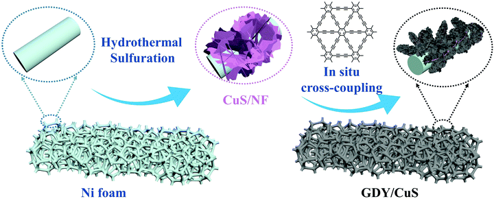
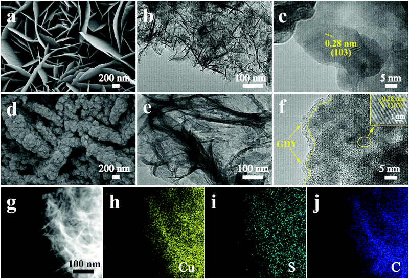
3D hierarchical nanoarchitectures were synthesized through a novel in situ polymerization approach, in which GDY nanosheets were directly in situ grown on the surface of pre-prepared CuS. The optical pictures of the fabricated samples with an apparent color change are displayed in Fig. S1 (ESI†). The fabrication process of a GDY/CuS heterostructure catalyst involves two steps (Scheme 1). First, CuS nanosheet arrays were grown on the Ni foam through a hydrothermal and subsequent sulfuration method. The SEM images of the cleaned Ni foam are presented in Fig. S2 (ESI†). Moreover, Fig. S3 (ESI†) shows the SEM images and XRD pattern of the Cu2O precursor. After the process of sulfuration, the CuS/NF was obtained and used as the substrate for the in situ growth of GDY via a cross-coupling reaction. Finally, the GDY/CuS hybrid catalyst with an interpenetrating hierarchical nanostructure was successfully fabricated.Fig. 1a shows the scanning electron microscopic (SEM) image of the CuS nanosheet arrays. It can be clearly seen that the smooth and razor-like nanosheets stacked uniformly, forming a 3D architecture with an open structure. The low-magnification SEM images of CuS are displayed in Fig. S4 (ESI†). The nanosheets are uniformly distributed with a vertical arrangement. The transmission electron microscopic (TEM) image of CuS (Fig. 1b) shows a gauzy nanosheet morphology. An interlayer spacing of 0.28 nm corresponding to the (103) crystal plane of CuS is observed in the high resolution transmission electron microscopic (HRTEM, Fig. 1c) image. The morphology of GDY on Ni foam is also shown in Fig. S5 (ESI†). It can be clearly seen that the vertically cross-linked nanowalls with abundant sub-micrometer voids appear (Fig. S5a, ESI†). The thin GDY nanosheets morphology is further verified by the TEM image (Fig. S5b, ESI†), in accordance with the previous report.47Fig. 1d displays the SEM image of the heterostructure composite after the in situ growth of GDY, it can be distinctly observed that the surface of CuS becomes rough. GDY nanosheets are completely covered on the surface of CuS, which presents a uniform and dense morphology, leading to the formation of a rough surface. Moreover, many independently GDY-coated CuS nanosheets are interwoven with each other, resulting in a hierarchical 3D porous network. Therefore, it is not surprising that the GDY/CuS composite possesses a large surface area as compared with pristine CuS. From the TEM image (Fig. 1e), the GDY/CuS composite retains the thin flake morphology. In the HRTEM images (Fig. 1f), the obvious wrapping structure between GDY and CuS is presented and the thickness of GDY is approximately 2–3 nm. The interlayer spacing of CuS (0.28 nm) is also observed in this heterostructure composite. Fig. 1g–j shows the elemental energy-dispersive X-ray spectroscopy (EDX) mapping images of Cu, S and C, demonstrating the uniform distribution of these three elements in the whole nanosheets. In addition, as displayed in Fig. S6 (ESI†), the thickness of individual composite nanosheets are further confirmed to be just a few nanometers by atomic force microscopy (AFM), corresponding to the above TEM results. Those results show strong evidence of the successful fabrication of GDY/CuS heterostructure composites and the intimate contact between GDY and CuS. According to previous research,50,51 the larger surface area and intimate contact could provide more reaction sites and formed effective electron transport pathways, which are beneficial to the improvement of the catalytic performance.
Fig. 2a shows the X-ray diffraction (XRD) patterns of CuS and GDY/CuS. All the characteristic peaks of pristine CuS can be indexed to the CuS phase (JCPDS no. 06-0464), except two strong peaks positioned at 44° and 53°, which are assigned to Ni foam. Only the two weaker characteristic peaks are found in GDY/CuS because of the entire coating of GDY and the strong diffraction influence of the Ni foam substrate. Raman spectroscopy is a powerful tool to investigate the molecular structure of carbon materials. As depicted in Fig. 2b, pristine CuS exhibits the characteristic peak at 262 cm−1 and 470 cm−1, corresponding to the CuS phase and stretching vibration of the S–S bond, respectively.49 The Raman spectrum of GDY is also shown in Fig. S7 (ESI†). Two prominent peaks around 1364 cm−1 and 1590 cm−1 can be ascribed to the D and G bands. The essential peaks of the vibration of conjugated diyne links (–C![[triple bond, length as m-dash]](https://www.rsc.org/images/entities/char_e002.gif) C–C
C–C![[triple bond, length as m-dash]](https://www.rsc.org/images/entities/char_e002.gif) C–) are also clearly observed at 1951 cm−1 and 2188 cm−1.52 For GDY/CuS, in addition to the vibrational peaks from CuS, the shifts in the diffraction peaks of GDY to a lower wavenumber (1378, 1520, 1934 and 2169 cm−1) are noticeable, indicating the formation of a strong chemical interaction between GDY and CuS, which could play an important role in the catalytic reaction. The XRD and Raman results further verify the successful preparation of the expected GDY/CuS heterostructure composite.
C–) are also clearly observed at 1951 cm−1 and 2188 cm−1.52 For GDY/CuS, in addition to the vibrational peaks from CuS, the shifts in the diffraction peaks of GDY to a lower wavenumber (1378, 1520, 1934 and 2169 cm−1) are noticeable, indicating the formation of a strong chemical interaction between GDY and CuS, which could play an important role in the catalytic reaction. The XRD and Raman results further verify the successful preparation of the expected GDY/CuS heterostructure composite.
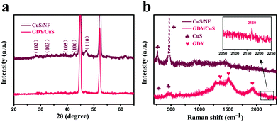 | ||
| Fig. 2 (a) XRD patterns and (b) Raman spectra for pristine CuS and GDY/CuS (inset: enlargement of the selected region). | ||
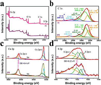
To further investigate the elemental composition and chemical state of the samples, X-ray photoelectron spectroscopy (XPS) was employed. Fig. 3a displays the survey spectra of pristine CuS and GDY/CuS, proving the existence of Cu, S, and C elements in the samples. The strong C signal in GDY/CuS indicates the successful growth of GDY on CuS and the weak signal of C in the pristine CuS originates from the absorption of carbon in the atmosphere. The high-resolution XPS spectra of C 1s for GDY/CuS and pure GDY are presented. For pure GDY, the four peaks with the binding energy (BE) of 284.4 eV, 285.0 eV, 286.6 eV, and 288.5 eV are assigned to C–C (sp2), C–C (sp), C–O, and C![[double bond, length as m-dash]](https://www.rsc.org/images/entities/char_e001.gif) O, respectively (Fig. 3b).47 For the GDY/CuS sample, according to the previous report,50 the presence of an extra peak at 290.0 eV is attributed to the π–π* transition, suggesting the restoration of the delocalized π conjugation and electronic interaction between GDY and CuS. The high-resolution XPS spectra of Cu 2p for pure CuS and GDY/CuS in Fig. 3c show two major peaks corresponding to Cu 2p1/2 and Cu 2p3/2, respectively. The corresponding satellite peaks (identified as “Sat.”) are also found, implying the existence of Cu(II). Moreover, the peak of Cu 2p1/2 in GDY/CuS evidently shifts to a lower binding energy. Similarly, as shown in Fig. 3d, the binding energy of S 2p1/2 in GDY/CuS also exhibited a red shift (0.22 eV) compared to that in pure CuS. In addition, the binding energy of S 2p in GDY/CuS became smaller and broader, mainly due to the formation of the low-coordination S atoms on the surface of CuS. In the polymerization of GDY, some copper ions in CuS were dissociated and then acted as catalysts for the growth of GDY. As a result, the coordination number of S became lower due to the escape of S atoms. According to the above experimental analysis, after the in situ growth of GDY, the characteristic peaks of Cu and S significantly shift to lower energy, demonstrating the strong electronic interaction between GDY and CuS, which is consistent with the Raman results.47,53
O, respectively (Fig. 3b).47 For the GDY/CuS sample, according to the previous report,50 the presence of an extra peak at 290.0 eV is attributed to the π–π* transition, suggesting the restoration of the delocalized π conjugation and electronic interaction between GDY and CuS. The high-resolution XPS spectra of Cu 2p for pure CuS and GDY/CuS in Fig. 3c show two major peaks corresponding to Cu 2p1/2 and Cu 2p3/2, respectively. The corresponding satellite peaks (identified as “Sat.”) are also found, implying the existence of Cu(II). Moreover, the peak of Cu 2p1/2 in GDY/CuS evidently shifts to a lower binding energy. Similarly, as shown in Fig. 3d, the binding energy of S 2p1/2 in GDY/CuS also exhibited a red shift (0.22 eV) compared to that in pure CuS. In addition, the binding energy of S 2p in GDY/CuS became smaller and broader, mainly due to the formation of the low-coordination S atoms on the surface of CuS. In the polymerization of GDY, some copper ions in CuS were dissociated and then acted as catalysts for the growth of GDY. As a result, the coordination number of S became lower due to the escape of S atoms. According to the above experimental analysis, after the in situ growth of GDY, the characteristic peaks of Cu and S significantly shift to lower energy, demonstrating the strong electronic interaction between GDY and CuS, which is consistent with the Raman results.47,53
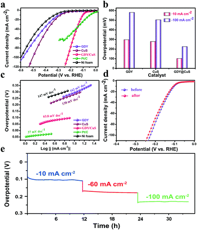
To assess the performance of GDY/CuS (mass loading: 2.6 mg cm−2) for the hydrogen evolution reduction, the linear sweep voltammetry (LSV) polarization curves were first recorded. As displayed in Fig. 4a, pure GDY grown on Ni foam possesses negligible cathode current at the low overpotential region. This unsatisfactory activity is in agreement with the case that used graphdiyne-wrapped FeCH nanosheets as the catalysts for hydrogen evolution.44 For comparison, the HER activity of Ni foam and Pt/C (20%) were also measured. As expected, pure Ni foam exhibited the worst performance, while the Pt/C electrode exhibited an excellent activity with negligible overpotential. Moreover, the catalytic performance of the as-prepared CuS nanosheets was comparable to that of the other reported CuS catalysts.54,55 In comparison with the polarization curve of pure GDY and pristine CuS, the GDY/CuS heterostructure composite exhibited a prompt response to an applied potential and a rapid increment of current at more negative potentials, which can be ascribed to the significantly enhanced activity for hydrogen evolution. As can be seen in Fig. 4b, it needs only 106 mV and 224 mV overpotential for GDY/CuS to reach the current density of 10 mA cm−2 and 100 mA cm−2, respectively. This is much better than that of pristine CuS (279 mV and 505 mV) and pure GDY (298 mV and 581 mV). The Tafel plot is an important parameter for evaluating the reaction kinetics of HER. Fig. 4c shows the Tafel plots for all the as-prepared electrodes. Impressively, the GDY/CuS heterostructure electrode has a Tafel slope of 63.8 mV dec−1, which is close to that of Pt/C (37 mV dec−1) and much smaller than that of pristine CuS (138 mV dec−1) and pure GDY (162 mV dec−1). This revealed that between the Volmer and Heyrovsky step in the HER process, Heyrovsky is the rate-limiting step for GDY/CuS.56 Based on the Tafel plot, the exchange current density (j0) is also obtained (Fig. S8, ESI†). The j0 is calculated to be 160 μA cm−2 for the GDY/CuS heterostructure catalyst, which is 1.9 times that of the pristine CuS nanosheets (85 μA cm−2) and 2.7 times that of pure GDY on Ni foam. By contrast, the overpotential, Tafel slope and j0 for the GDY/CuS heterostructure catalyst are superior to other reported values for the non-noble metal HER catalysts in alkaline aqueous media (Table S1, ESI†). Thus, the above results powerfully demonstrate that our GDY/CuS heterostructure composite is a highly efficient electrocatalyst for the hydrogen evolution reaction. In addition to the catalytic activity, stability is another major criterion to evaluate the performance of an electrocatalyst. Therefore, a long-time electrochemical stability test was performed using the multi-level chronopotentiometry. As illustrated in Fig. 4d, the overpotential of the as-prepared GDY/CuS electrocatalyst exhibits a very slow change at the given current density of 10 mA, 60 mA, and 100 mA cm−2 for nearly 35 hours. Moreover, the stability is further examined by a continuous cyclic voltammetry (CV) method. The polarization curves present a slight variation before and after 5000 CV cycles. The negligible difference presented in the chronopotentiometry and LSV curves demonstrate the superior stability of the as-prepared GDY/CuS electrodes in a long-term electrochemical process. The morphology and composition of the GDY/CuS electrode after stability tests were also investigated. Fig. S9 (ESI†) shows the low-resolution SEM image and corresponding mapping images of GDY/CuS after the stability test, which maintains the original morphology as well as the uniform distribution of Cu, S, and C elements. From the TEM images in Fig. S10 (ESI†), the GDY coating layer can be clearly observed, revealing that the wrapped heterostructure of GDY and CuS nanosheets is preserved well. Moreover, the interplanar spacing of 0.28 nm corresponding to the (103) plane of CuS is still observed. In addition, as shown in Fig. S11 (ESI†), the XPS spectra exhibit no obvious variation between the fresh and after cycling sample, indicating the surface chemical states of the GDY/CuS heterostructure composite have not changed. Therefore, it is an undeniable fact that the as-prepared GDY/CuS electrocatalyst is inherently stable for the HER in alkaline media due to the effective coating of GDY.
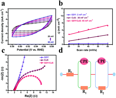
To gain insight into the origin of the excellent performance of the GDY/CuS electrocatalyst, the electrochemical active surface area (ECSA) was first measured by cyclic voltammetry. It is well known that the double-layer capacitance (Cdl), which can be calculated using the CV method, is proportional to the ECSA.38Fig. 5a and Fig. S12 (ESI†) show the typical CV curves at different scan rates for GDY/CuS, pure GDY, and CuS, respectively. As depicted in Fig. 5b, the GDY/CuS electrode possesses a Cdl of 45 mF cm−2, which is 1.5 times that of the CuS nanosheets (30 mF cm−2) and 22.5 times that of GDY (2 mF cm−2), meaning an increase in ECSA with more exposure of catalytic active sites. This result is consistent with the SEM analysis previously. The more catalytic activity sites exposed, the better the performance. In order to further evaluate the intrinsic activity of the fabricated catalysts, the HER current density is normalized by ECSA. In Fig. S13 (ESI†), the GDY/CuS still exhibits a much larger current density than pristine CuS at the same applied potential, demonstrating the enhanced intrinsic catalytic activity of the hybrid composite after the in situ growth of GDY. Furthermore, electrochemical impedance spectroscopy (EIS) was performed to assess the electrode kinetics in the HER process and the corresponding equivalent circuit model is also presented (Fig. 5d). As shown in Fig. 5c, it can be clearly seen that after the coating of GDY, the Nyquist plots of the heterostructure composite presented a notable decrease in the charge-transfer resistance (R), indicating the desirable electron transport and quick catalytic kinetics. In the equivalent circuit model, Rs is the solution resistance. The constant phase element (CPE) is related to the double-layer capacitance and the R is the charge transfer resistance. According to the fitting results (Table S2 ESI†), GDY/CuS exhibits the smallest solution resistance (1.43 Ω) and the charge transfer resistance (9.04 Ω), which are much smaller than that of CuS (Rs = 2.02 Ω, R = 190 Ω) and GDY (Rs = 2.61 Ω, R = 2492 Ω). This result also demonstrates the most favorable charge-transfer performance of GDY/CuS, which benefits the HER catalytic activity. It is reasonable to believe that the intimate contact derived from the in situ growth of GDY, and the intrinsic high electronic conductivity of GDY play a vital role in the process of electron transport.7
In accordance with the above discussions, the excellent HER performance of our GDY/CuS heterostructure electrocatalyst can be ascribed to the following factors: (1) compared with pristine CuS, the GDY/CuS heterostructure composite possesses more catalytically active surface area, resulting in more active sites participating in the reaction.47,57 (2) Benefiting from the 3D hierarchical nano-structure as well as the porous property, the electrolyte diffusion and gas release are greatly facilitated, leading to rapid HER kinetics.58 (3) Because of the smart design, GDY can be grown in situ without the aid of additional catalysts. The intimate connection, particularly the strong electronic interactions between GDY and CuS, which is demonstrated by the Raman and XPS results, can efficiently improve the conductivity and accelerate the charge transfer.50 (4) The enhancement in the intrinsic catalytic activity of the GDY/CuS heterostructure composite originates from the synergistic effect between GDY and CuS. (5) The effective coating of GDY results in an outstanding durability of GDY/CuS catalyst. Therefore, it is reasonable to say that the GDY/CuS heterostructure electrocatalyst exhibits a pre-eminent performance for the hydrogen evolution reaction.
4. Conclusions
In summary, GDY-coated CuS nanosheets heterostructure electrocatalyst was successfully fabricated via a simple “hitting two birds with one stone” method. This straightforward strategy achieved the aims of the effective coating of GDY and significantly improved the catalytic activity simultaneously. Benefiting from the 3D porous heterostructure and unique properties provided by GDY, the novel GDY/CuS catalyst exhibited a large surface area with many active sites and effective electron transfer, all of which resulted in the superior HER performance in alkaline electrolytes. The designed GDY/CuS hybrid catalyst only needed a small overpotential of 106 mV to reach the current density of 10 mA cm−2 and exhibited an excellent stability in long-term electrochemical testing. Our study establishes a novel and affordable approach to design high efficiency GDY-coated electrocatalysts applied in the hydrogen evolution reaction and further overall water splitting.Conflicts of interest
There are no conflicts of interest to declare.Acknowledgements
The author acknowledged financial support from the National Natural Science Foundation of China (No. 21771114), MOE 111 (B12015), Natural Science Foundation of Tianjin (17JCYBJC40900, 18YFZCGX00580) and the Fundamental Research Funds for the Central Universities. M. Y. thanks to the financial support from “Thousand Youth Talents Plan of China”.Notes and references
- Z. W. Seh, J. Kibsgaard, C. F. Dickens, I. Chorkendorff, J. K. Nørskov and T. F. Jaramillo, Science, 2017, 355, 6321 CrossRef PubMed.
- F. Bonaccorso, L. Colombo, G. Yu, M. Stoller, V. Tozzini, A. C. Ferrari, R. S. Ruoff and V. Pellegrini, Science, 2015, 347, 1246501 CrossRef PubMed.
- H. Zhou, F. Yu, Y. Liu, J. Sun, Z. Zhu, R. He, J. Bao, W. A. Goddard, S. Chen and Z. Ren, Energy Environ. Sci., 2017, 10, 1487 RSC.
- N. Mahmood, Y. Yao, J. Zhang, L. Pan, X. Zhang and J. Zou, Adv. Sci., 2018, 5, 1700464 CrossRef PubMed.
- T. Wang, H. Xie, M. Chen, A. D’Aloia, J. Cho, G. Wu and Q. Li, Nano Energy, 2017, 42, 69 CrossRef CAS.
- J. Lai, B. Huang, Y. Chao, X. Chen and S. Guo, Adv. Mater., 2019, 31, 1805541 CrossRef PubMed.
- S. Jeoung, B. Seo, J. M. Hwang, S. H. Joo and H. R. Moon, Mater. Chem. Front., 2017, 1, 973 RSC.
- Z. Zhu, H. Yin, C. T. He, M. Al-Mamun, P. Liu, L. Jiang, Y. Zhao, Y. Wang, H. G. Yang, Z. Tang, D. Wang, X. M. Chen and H. Zhao, Adv. Mater., 2018, 30, 1801171 CrossRef PubMed.
- G. Zhang, X. Zheng, Q. Xu, J. Zhang, W. Liu and J. Chen, J. Mater. Chem. A, 2018, 6, 4793 RSC.
- H. Yan, Y. Xie, Y. Jiao, A. Wu, C. Tian, X. Zhang, L. Wang and H. Fu, Adv. Mater., 2018, 30, 1704156 CrossRef PubMed.
- L. Yu, H. Zhou, J. Sun, F. Qin, D. Luo, L. Xie, F. Yu, J. Bao, Y. Li, Y. Yu, S. Chen and Z. Ren, Nano Energy, 2017, 41, 327 CrossRef CAS.
- M. Gong, W. Zhou, M. C. Tsai, J. Zhou, M. Guan, M. C. Lin, B. Zhang, Y. Hu, D. Y. Wang, J. Yang, S. J. Pennycook, B. J. Hwang and H. Dai, Nat. Commun., 2014, 5, 4695 CrossRef CAS PubMed.
- S. Jing, J. Lu, G. Yu, S. Yin, L. Luo, Z. Zhang, Y. Ma, W. Chen and P. K. Shen, Adv. Mater., 2018, 30, 1705979 CrossRef PubMed.
- Y. Shi, Y. Zhou, D. R. Yang, W. X. Xu, C. Wang, F. B. Wang, J. J. Xu, X. H. Xia and H. Y. Chen, J. Am. Chem. Soc., 2017, 139, 15479 CrossRef CAS PubMed.
- X. Zou, Y. Wu, Y. Liu, D. Liu, W. Li, L. Gu, H. Liu, P. Wang, L. Sun and Y. Zhang, Chem, 2018, 4, 1139 CAS.
- S. H. Li, N. Zhang, X. Xie, R. Luque and Y. J. Xu, Angew. Chem., 2018, 130, 13266 CrossRef.
- J. Ren, L. Chen, C. Weng and Z. Yuan, Mater. Chem. Front., 2018, 2, 1987 RSC.
- Y. Qu, H. Medina, S. W. Wang, Y. C. Wang, C. W. Chen, T. Y. Su, A. Manikandan, K. Wang, Y. C. Shih, J. W. Chang, H. C. Kuo, C. Y. Lee, S. Y. Lu, G. Shen, Z. M. Wang and Y. L. Chueh, Adv. Mater., 2016, 28, 9831 CrossRef CAS PubMed.
- P. F. Liu, L. Zheng, L. R. Zheng and H. G. Yang, Mater. Chem. Front., 2018, 2, 1725 RSC.
- Y. Huang, J. Ge, J. Hu, J. Zhang, J. Hao and Y. Wei, Adv. Energy Mater., 2018, 8, 1701601 CrossRef.
- N. Han, K. R. Yang, Z. Lu, Y. Li, W. Xu, T. Gao, Z. Cai, Y. Zhang, V. S. Batista, W. Liu and X. Sun, Nat. Commun., 2018, 9, 924 CrossRef PubMed.
- B. Hinnemann, P. G. Moses, J. Bonde, K. P. Jørgensen, J. H. Nielsen, S. Horch, I. Chorkendorff and J. K. Nørskov, J. Am. Chem. Soc., 2005, 127, 5308 CrossRef CAS PubMed.
- T. F. Jaramillo, K. P. Jørgensen, J. Bonde, J. H. Nielsen, S. Horch and I. Chorkendorff, Science, 2007, 317, 100 CrossRef CAS PubMed.
- J. Xie, J. Zhang, S. Li, F. Grote, X. Zhang, H. Zhang, R. Wang, Y. Lei, B. Pan and Y. Xie, J. Am. Chem. Soc., 2013, 135, 1788 Search PubMed.
- L. An, L. Huang, P. Zhou, J. Yin, H. Liu and P. Xi, Adv. Funct. Mater., 2015, 25, 6814 CrossRef CAS.
- S. Q. Liu, H. R. Wen, Y. Guo, Y. W. Zhu, X. Z. Fu, R. Sun and C. P. Wong, Nano Energy, 2018, 44, 7 CrossRef CAS.
- Y. Zhao, H. Tang, N. Yang and D. Wang, Adv. Sci., 2018, 5, 1800959 CrossRef PubMed.
- C. Huang, Y. Li, N. Wang, Y. Xue, Z. Zuo, H. Liu and Y. Li, Chem. Rev., 2018, 118, 7744 CrossRef CAS PubMed.
- G. Li, Y. Li, H. Liu, Y. Guo, Y. Li and D. Zhu, Chem. Commun., 2010, 46, 3256 RSC.
- Y. Xue, Y. Li, J. Zhang, Z. Liu and Y. Zhao, Sci. China: Chem., 2018, 61, 765 CrossRef CAS.
- Z. Jia, Y. Li, Z. Zuo, H. Liu, C. Huang and Y. Li, Acc. Chem. Res., 2017, 50, 2470 CrossRef CAS PubMed.
- Y. Li, L. Xu, H. Liu and Y. Li, Chem. Soc. Rev., 2014, 43, 2572 RSC.
- M. Long, L. Tang, D. Wang, Y. Li and Z. Shuai, ACS Nano, 2011, 5, 2593 CrossRef CAS PubMed.
- D. Malko, C. Neiss, F. Viñes and A. Görling, Phys. Rev. Lett., 2012, 108, 086804 CrossRef PubMed.
- N. Yang, Y. Liu, H. Wen, Z. Tang, H. Zhao, Y. Li and D. Wang, ACS Nano, 2013, 7, 1504 CrossRef CAS PubMed.
- Y. Xue, B. Huang, Y. Yi, Y. Guo, Z. Zuo, Y. Li, Z. Jia, H. Liu and Y. Li, Nat. Commun., 2018, 9, 1460 CrossRef PubMed.
- X. P. Yin, H. J. Wang, S. F. Tang, X. L. Lu, M. Shu, R. Si and T. B. Lu, Angew. Chem., Int. Ed., 2018, 57, 9382 CrossRef CAS PubMed.
- G. Shi, C. Yu, Z. Fan, J. Li and M. Yuan, ACS Appl. Mater. Interfaces, 2019, 11, 2662 CrossRef CAS PubMed.
- J. Li, X. Gao, X. Jiang, X. B. Li, Z. Liu, J. Zhang, C. H. Tung and L. Z. Wu, ACS Catal., 2014, 7, 5209 CrossRef.
- L. Hui, Y. Xue, B. Huang, H. Yu, C. Zhang, D. Zhang, D. Jia, Y. Zhao, Y. Li, H. Liu and Y. Li, Nat. Commun., 2018, 9, 5309 CrossRef PubMed.
- Y. Xue, J. Li, Z. Xue, Y. Li, H. Liu, D. Li, W. Yang and Y. Li, ACS Appl. Mater. Interfaces, 2016, 8, 31083 CrossRef CAS.
- Y. Zhao, J. Wan, H. Yao, L. Zhang, K. Lin, L. Wang, N. Yang, D. B. Liu, L. Song, J. Zhu, L. Gu, L. Liu, H. Zhao, Y. Li and D. Wan, Nat. Chem., 2018, 10, 924 CrossRef CAS PubMed.
- Q. Lv, W. Si, J. He, L. Sun, C. Zhang, N. Wang, Z. Yang, X. Li, X. Wang, W. Deng, Y. Long, C. Huang and Y. Li, Nat. Commun., 2018, 9, 3376 CrossRef PubMed.
- L. Hui, D. Jia, H. Yu, Y. Xue and Y. Li, ACS Appl. Mater. Interfaces, 2019, 11, 2618 CrossRef CAS PubMed.
- H. Ren, H. Shao, L. Zhang, D. Guo, Q. Jin, R. Yu, L. Wang, Y. Li, Y. Wang, H. Zhao and D. Wang, Adv. Energy Mater., 2015, 5, 1500296 CrossRef.
- J. Wang, H. Tang, H. Wang, R. Yu and D. Wang, Mater. Chem. Front., 2017, 3, 414 RSC.
- L. Hui, Y. Xue, F. He, D. Jia and Y. Li, Nano Energy, 2019, 55, 135 CrossRef CAS.
- X. Gao, J. Li, R. Du, J. Zhou, M. Y. Huang, R. Liu, J. Li, Z. Xie, L. Z. Wu, Z. Liu and J. Zhang, Adv. Mater., 2017, 29, 1605308 CrossRef PubMed.
- Z. Zhao, X. Peng, X. Liu, X. Sun, J. Shi, L. Han, G. Li and J. Luo, J. Mater. Chem. A, 2017, 5, 20239 RSC.
- H. Yu, Y. Xue, L. Hui, C. Zhang, Y. Li, Z. Zuo, Y. Zhao, Z. Li and Y. Li, Adv. Mater., 2018, 30, 1707082 CrossRef PubMed.
- G. Shi, L. Yu, X. Ba, X. Zhang, J. Zhou and Y. Yu, Dalton Trans., 2017, 46, 10569 RSC.
- Y. Xue, Z. Zuo, Y. Li, H. Liu and Y. Li, Small, 2017, 13, 1700936 CrossRef PubMed.
- Q. Xu, Y. Liu, H. Jiang, Y. Hu, H. Liu and C. Li, Adv. Energy Mater., 2019, 9, 1802553 CrossRef.
- Y. Li, Y. Wang, B. Pattengale, J. Yin, L. An, F. Cheng, Y. Li, J. Huang and P. Xi, Nanoscale, 2017, 9, 9230 RSC.
- L. Ji, L. Zhu, J. Wang and Z. Chen, Electrochim. Acta, 2017, 252, 516 CrossRef CAS.
- X. Gao, H. Zhang, Q. Li, X. Yu, Z. Hong, X. Zhang, C. Liang and Z. Lin, Angew. Chem., Int. Ed., 2016, 128, 6398 CrossRef.
- G. Shi, L. Yang, Z. Liu, X. Chen, J. Zhou and Y. Yu, Appl. Surf. Sci., 2018, 427, 1165 CrossRef CAS.
- L. Yu, I. K. Mishra, Y. Xie, H. Zhou, J. Sun, J. Zhou, Y. Ni, D. Luo, F. Yu, Y. Yu, S. Chen and Z. Ren, Nano Energy, 2018, 53, 492 CrossRef CAS.
Footnotes |
| † Electronic supplementary information (ESI) available. See DOI: 10.1039/c9qm00064j |
| ‡ These authors contributed equally to this work. |
| This journal is © the Partner Organisations 2019 |

