 Open Access Article
Silver nanowire/nickel hydroxide nanosheet composite for a transparent electrode and all-solid-state supercapacitor†
Haojin
Du
a,
Ying
Pan
a,
Xiao
Zhang
a,
Fuyang
Cao
a,
Tao
Wan
a,
Haiwei
Du
 *b,
Rakesh
Joshi
 a and
Dewei
Chu
 *a
*a
aSchool of Materials Science and Engineering, UNSW Sydney, NSW 2052, Australia. E-mail: d.chu@unsw.edu.au
bSchool of Chemistry and Chemical Engineering, Anhui University, Hefei 230061, P. R. China. E-mail: haiwei.du@hotmail.com
First published on 29th August 2018
Abstract
Silver nanowire (Ag NW) based composites have shown a great potential not just in transparent electrodes but in diverse functional applications. The main challenge of Ag NW film is the large junction resistance originating from the weak NW contacts. In this paper, we report a simple method to combine ultrathin nickel hydroxide (Ni(OH)2) nanosheets (NSs) and Ag NWs as a composite for transparent electrode and all-solid-state supercapacitor applications. On the one hand, the Ni(OH)2 NSs were simply coated on Ag NW film and the sheet resistance was decreased significantly without compromising the optical transmittance, owing to the improved junction contacts among NWs and the ultrathin nanostructure of Ni(OH)2 NSs. The optimum Ag NW/Ni(OH)2 NS composite showed not only an excellent optoelectronic performance (a sheet resistance of 18.56 Ω □−1 and a transmittance of 90.26%) but also improved thermal stability. On the other hand, the Ag NW/Ni(OH)2 NS composite was designed for all-solid-state flexible supercapacitors with a high specific capacitance, moderate cycle stability and good mechanical flexibility, indicating a promising application in flexible supercapacitors.
Introduction
As a very promising alternative for the commercial indium tin oxides, silver nanowire (Ag NW) has been considered to be the material of next-generation transparent electrodes (TEs) in view of its large-scale industrial production and better stretching/bending performances as well as its very good compatibility with advanced fabrication technologies such as ink-jet printing and roll-to-roll manufacturing. However, the conductivity of Ag NW networks is mainly limited by the relatively large contact resistance due to loose contacts at the nanowire junctions, and this remaining issue hinders applications somewhat. Although various post-treatments1 including thermal annealing, mechanical pressing, plasma, electron beam irradiation and laser welding are being developed to greatly reduce the wire–wire junction resistance, some disadvantages such as higher temperature and costly irradiation apparatus still cannot be neglected. Compared with these welding strategies, simply depositing a coating layer on the Ag NW film to form a hybrid or bilayer composite is very promising since the coating layer can not only strengthen the NW junction contact but also infiltrate into the empty spaces among the Ag NW network which remain insulating and usually hinder the electron transport. Usually, the significant effects of the coating layer are (i) enlarging the contact area between Ag NWs, (ii) minimizing the surface roughness, (iii) increasing adhesion of the Ag NWs to the substrate, (iv) inhibiting oxidation/corrosion, and more importantly (v) facilitating electron conduction. So far, conductive materials such as PEDOT:PSS2 and graphene,3 semiconductor metal oxides4,5 and even insulating polymer matrixes like polyvinyl alcohol and chitosan,6,7 have been utilized to effectively reduce the resistance of Ag NW electrodes. Inspired by these designs, graphene-like nanosheets (NSs) serving as a coating layer on the Ag NW network are expected to enhance the electrical conductivity of Ag NWs without sacrificing high transmittance because of the good optical performances of ultrathin NSs.Moreover, different composites consisting of Ag NW and other coatings have been successfully explored to show diverse applications either in powder catalysts or in physical devices in the past decades. In particular, silver nanomaterials usually play a critical role in electrochemical energy storage and conversion devices,8 acting as a current collector or even directly participating in the electrochemical reactions. Most of the previous works have mainly focused on monofunctional applications such as electrode, biosensor or supercapacitor while multiple applications of the Ag NW based composites are highly desired (as shown in Table S1†). For example, a multifunctional Ag grid/PEDOT:PSS hybrid electrode was fabricated to show a great potential in both TE application and a solid-state supercapacitor device.9 However, the PEDOT:PSS is actually a conductive polymer and the capacitance can be further enhanced if the coating layer has a good charge-storage capacity. Unlike the conventional electric double layer capacitors (EDLCs), the charge storage in transition metal hydroxides occurs via fast and reversible redox reactions, resulting in a larger capacitance due to a dominant contribution from battery-type behavior.10 As a typical representative, nickel hydroxide (Ni(OH)2) is very attractive in terms of its low cost, various morphologies, unique layered structure with a large interlayer spacing, and considerable theoretical capacitance.11
Herein, Ni(OH)2 NSs were coated on Ag NW film to form a composite for a TE and all-solid-state supercapacitor. On the one hand, as a semiconductor12 like metal oxides, graphene-like ultrathin Ni(OH)2 NSs can effectively bridge the Ag NWs by filling the empty space without significantly affecting the transparency, making a contribution to optimize the optoelectronic performances. On the other hand, the excellent electrochemical performances of Ni(OH)2 NSs13 enable the composite to be a promising electrode for supercapacitor devices. The prepared composite presents a low sheet resistance (Rs = 18.56 Ω □−1) with a high optical transmittance (∼90.26%). In addition, the all-solid-state flexible supercapacitor was fabricated by transferring the Ag NW/Ni(OH)2 NS composite onto a polydimethylsiloxane (PDMS) substrate, and the as-prepared device showed a good capacitance and mechanical flexibility.
Experimental
Materials
Silver nitrate (AgNO3, Mw: 169.87), polyvinylpyrrolidone (PVP) (Mw: 55![[thin space (1/6-em)]](https://www.rsc.org/images/entities/char_2009.gif) 000), sodium chloride (NaCl, Mw: 58.4), 1,2-propanediol (ρ: 1.036 g mL−1), nickel(II) nitrate hexahydrate (Ni(NO3)2·6H2O, Mw: 290.81), urea (Mw: 60.04), potassium hydroxide (KOH, Mw: 56.11), polyvinyl alcohol (PVA, Mw: 85
000), sodium chloride (NaCl, Mw: 58.4), 1,2-propanediol (ρ: 1.036 g mL−1), nickel(II) nitrate hexahydrate (Ni(NO3)2·6H2O, Mw: 290.81), urea (Mw: 60.04), potassium hydroxide (KOH, Mw: 56.11), polyvinyl alcohol (PVA, Mw: 85![[thin space (1/6-em)]](https://www.rsc.org/images/entities/char_2009.gif) 000–124
000–124![[thin space (1/6-em)]](https://www.rsc.org/images/entities/char_2009.gif) 000) and carbon paper (Fuel Cell Store). All the chemicals were purchased from Sigma-Aldrich and were used without further purification.
000) and carbon paper (Fuel Cell Store). All the chemicals were purchased from Sigma-Aldrich and were used without further purification.
Synthesis of silver nanowires
The synthesis of Ag NWs was conducted as reported by our previous study14 with a modification. First, 0.001 g NaCl was ultrasonically dissolved into 10 mL 1,2-propanediol. Then, 0.25 g PVP was put into 30 mL 1,2-propanediol and heated with magnetic stirring at 120 °C for 30 min. After cooling down to 60 °C, 3 mL NaCl solution was added into the solution with magnetic stirring for 3 min. Afterwards, 12 mL 1,2-propanediol containing 0.3057 g AgNO3 was added and the solution was heated at 150 °C with magnetic stirring for 60 min. Finally, the as-synthesised Ag NWs were washed five times by centrifugation using ethanol and deionized (DI) water, and redispersed into ethanol.Synthesis of nickel hydroxide NSs
First, 0.1454 g Ni(NO3)2·6H2O was dissolved into 2.5 mL DI water with magnetic stirring for 3 min. Then 10 mL 1,2-propanediol and 0.12 g urea were added. Afterwards, the obtained solution was transferred into a Teflon container and hydrothermally heated at 150 °C for 12 h. After cooling down to room temperature, the as-synthesised Ni(OH)2 NSs were washed three times by centrifugation using ethanol and DI water, and redispersed into DI water. Finally, the Ni(OH)2 NSs were ultrasonically exfoliated for 30 min (SONICS 750 Watt ultrasonic processor), and dispersed in DI water at a concentration of 0.12 mg mL−1.Fabrication of silver NW/nickel hydroxide TEs
First, glass slides (2 × 2 cm2, thickness of 1.6 mm) were cleaned by ethanol and DI water, and treated by the UV/Ozone surface processor (Sen Lights Corporation, Japan) for 5 min. Then, the Ag NW solution was spin coated several times onto the glass slides. Afterwards, 20 μL solution containing the Ni(OH)2 NSs was drop coated 1–5 times onto the Ag NW films. The repeating coating cycles were conducted after the films were dried at room temperature. The schematic of TE fabrication is depicted in Scheme 1a.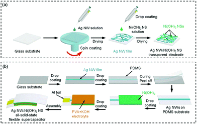 | ||
| Scheme 1 Schematic of the fabrication of (a) the Ag NW/Ni(OH)2 NS TE and (b) the all-solid-state flexible supercapacitor. | ||
Synthesis of the solid electrolyte and PDMS
First, 0.5 g PVA was dispersed into 5 mL DI water and then heated at 95 °C under magnetic stirring until the PVA was completely dissolved. Second, 1 mL 12.5 M KOH solution was added dropwise into the viscous PVA solution under magnetic stirring and the solution was dried until a gel was obtained. The gel was placed in a vacuum box to remove the gas bubbles. For the flexible device, PDMS (Sylgard 184, DowCorning) was prepared by pouring a mixture of base and curing agent (10![[thin space (1/6-em)]](https://www.rsc.org/images/entities/char_2009.gif) :
:![[thin space (1/6-em)]](https://www.rsc.org/images/entities/char_2009.gif) 1 by weight) into a mould.
1 by weight) into a mould.
Fabrication of silver NW/nickel hydroxide NS based all-solid-state supercapacitors
Ag NWs were coated onto a glass substrate to achieve a low resistance (less than 5 Ω). Then the PDMS liquid was poured onto the Ag NW film, and cured at 80 °C for 1 h. After being peeled off, the Ag NWs were transferred onto the PDMS substrate. The Ni(OH)2 NS solution as the supercapacitive material was drop coated onto the Ag NW electrode. After drying at room temperature, PVA/KOH gel was coated onto the Ni(OH)2 NS layer. Finally, two pieces of electrode were oppositely assembled to fabricate a sandwich structure, and the all-solid-state supercapacitor device was dried at 60 °C to evaporate the excess water. Then two aluminium foils were pasted onto the electrodes for electrochemical tests. The schematic of the supercapacitor device fabrication is depicted in Scheme 1b.Materials and device characterization
Structural analysis of the as-synthesized Ag NWs and Ni(OH)2 NSs was performed using an X-ray diffractometer with Cu Kα radiation (λ = 0.1541 nm). The microstructures were observed by transmission electron microscopy (TEM, FEI Tecnai G2) and scanning electron microscopy (SEM, FEI Nova NanoSEM 450). The sheet thickness of Ni(OH)2 was measured by atomic force microscopy (AFM, Bruker) using a Scanasyst probe. The chemical bonding states were determined by X-ray photoelectron spectroscopy (XPS, ESCALAB250Xi spectrometer). The transmittance of the TEs was determined using a PerkinElmer UV-visible spectrometer. The Rs values were determined using a Four-point Probe Resistance Tester (Zhuhai Kaivo Optoelectronic Technology Co., Ltd.). The electrochemical performance was investigated using the electrochemical workstation (Autolab PGSTAT302 N).Results and discussion
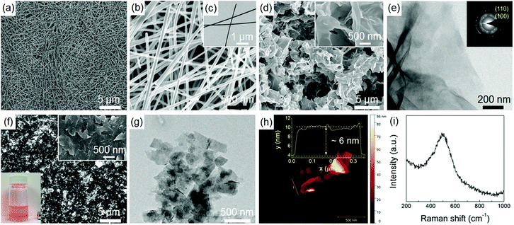
Fig. 1 shows the morphologies of Ag NWs and Ni(OH)2 NSs. Similar to the results in our previous work,14 the Ag NWs have a relatively uniform length and diameter, as shown in Fig. 1a–c. The as-synthesized Ni(OH)2 shows a free-standing 2D NS morphology (Fig. 1d) with a lateral size ranging from submicrometers to a few micrometres, and the wrinkled surface can be clearly seen in the TEM image (Fig. 1e). The selected area electron diffraction (SAED) pattern taken from the NSs is composed of two diffraction rings corresponding to the (100) and (110) planes of α-Ni(OH)2 (inset of Fig. 1e). Fig. 1f shows the SEM image of exfoliated Ni(OH)2 NSs. After the ultrasonic treatment, the large NSs have been exfoliated to many smaller nanoplatelets of a more uniform size, and the NSs are also flatter. As a result of the size reduction, the exfoliated Ni(OH)2 NSs form a well-dispersed colloidal suspension in water, as indicated by the clear Tyndall light scattering (inset photograph in Fig. 1f). The ultrathin and flat NS structure is also revealed by TEM (Fig. 1g). In order to determine the thickness of the NSs, the exfoliated Ni(OH)2 NSs were transferred onto a silicon substrate for AFM characterization (as shown in Fig. 1h) and the measured thickness from height profile is around 6 nm, indicating a very thin NS structure. Fig. 1i shows the Raman spectrum of the Ni(OH)2 NSs and the broad peak located at around 500 cm−1 is indicative of a defective or disordered Ni(OH)2.15Fig. 2a presents the XRD patterns of Ni(OH)2 NSs, Ag NWs, and the Ag NW/Ni(OH)2 NS composite. The as-synthesized Ag NWs display two main diffraction peaks that are well matched to the Ag standard peaks (JCPDS no. 04-0783). The diffraction peaks of the Ni(OH)2 NSs can be indexed to α-Ni(OH)2 (JCPDS no. 22-0444), and no secondary phase is observed. Meanwhile, the (001) diffraction peak has a very high intensity and the intensity ratio of I(001)/I(110) is remarkably large compared with that of the standard card. Since the α-Ni(OH)2 has a hexagonal layered structure, the Ni(OH)2 NSs show anisotropic growth with a preferential direction along the ab plane,16 resulting in a 2D NS structure, which is consistent with the microstructure observation (Fig. 1e and f). The composite contains both Ag NWs and Ni(OH)2 NSs without any structural change. The composition and surface state of the composite were further characterized by XPS (Fig. 2b–d), in which the impurities such as silicon and sodium are from the glass substrate. The binding energies of Ag 3d5/2 and Ag 3d3/2 located at ∼368.2 eV and ∼374.2 eV, respectively, correspond to metallic silver,17 and the Ni 2p3/2 located at ∼855.8 eV is characteristic of Ni2+ in Ni(OH)2.18
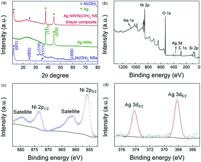 | ||
| Fig. 2 XRD patterns (a) of Ni(OH)2 NSs, Ag NWs, and the Ag NW/Ni(OH)2 NS composite. XPS of the Ag NW/Ni(OH)2 NS composite: survey scan (b), Ni 2p (c) and Ag 3d (d) spectra. | ||
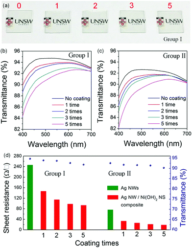
To study the effect of the Ni(OH)2 NS layer on the optical and electrical performances, Ag NW TEs with initial resistances of ∼245 Ω □−1 and ∼75 Ω □−1 were prepared first and then the Ni(OH)2 NSs were drop coated. The photographs (Fig. 3a) show that the Ag NW/Ni(OH)2 NS electrodes have a high transparency. After coating with a small amount of the Ni(OH)2 NSs, the optical property (Fig. 3b and c) is not compromised significantly because of the ultrathin NS structure.
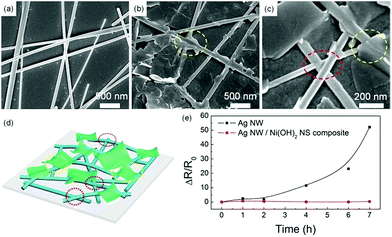
Meanwhile, the Rs reduces by around 50% first, and then changes slightly with the increasing coating times (Fig. 3d). Fig. 4a–c show the microstructures of the TEs before and after Ni(OH)2 NS coating. The contacts between the Ag NWs alone are very loose (Fig. 4a) thus the relatively large Rs cannot be avoided due to the weak electrical contacts and the empty voids in the NW network. After deposition of the Ni(OH)2 NS layer, the junction contacts and Rs value are greatly improved. The reduced Rs of the Ag NW/Ni(OH)2 NS composites should be attributed to the improvement of the NW junction contacts and the enhanced adhesion between the Ag NWs, Ni(OH)2 NSs and the substrate. On the one hand, the Ni(OH)2 NSs with different lateral areas can not only cover the NW junctions and infiltrate the empty spaces between the Ag NWs but also encapsulate the NW network as a coating layer (as shown in Fig. 4b–d), further increasing the conductive pathways by bridging a few unconnected nanowires. On the other hand, the NW contacts can be improved owing to the mechanical nanopressing effect5 of the Ni(OH)2 NSs and the capillary-force induced cold-welding. When the Ag NWs are covered by Ni(OH)2 NSs, the interfacial pressure can be a driving force to induce the welding effect at the NW junctions. In Fig. 4c, NW junctions with slightly compressed connections are clearly observed after coating with a Ni(OH)2 NS layer. It has also been reported that capillary-force by solvent evaporation often induces cold-welding at a junction. Here, the solvent of the Ni(OH)2 NS solution is water and only a small amount of solution (20 μL) is used for each coating. During the water evaporation process, the capillary-force, as a pull force, can bridge the separated NWs.19 Thus both mechanical nanopressing from the Ni(OH)2 NSs and the cold-welding during water evaporation should be responsible for the strengthened NW contacts and enhanced conductivity. Moreover, with the increasing coating times the Rs decreases only slightly, indicating that the nanopressing and bridging effects become less effective as the hybrid network may have already reached an optimum state. To further evaluate the electrical and optical properties of the Ag NW/Ni(OH)2 NS composite TEs, the Rs and transmittance at a wavelength of 550 nm were used to calculate the figure of merit (FoM) using the following equation defined by Haacke:20
| ΦTC = T10/Rs |
The ΦTC value is FoM 19.3 (10−3 Ω−1), based on the Rs of 18.56 Ω □−1 and the transmittance of 90.26%, and this value is comparable to that of the commercial ITO (21.9).
Another issue with Ag NWs is their thermal stability. It is found that Ag NWs often undergo a spheroidization process during heating, transforming from nanowires to fragments or even nanoparticles due to the reduction of surface energy. Since the beginning of coalescence takes place at 200 °C,21 Ag NWs and the Ag NW/Ni(OH)2 NS composite on the glass substrate were annealed at 200 °C for 7 h to evaluate their thermal stabilities. As shown in Fig. 4e, the Rs of the Ag NW electrode increases around 50 fold, while the Ag NW/Ni(OH)2 NS composite retains its original conductivity, and its resistance variation is very slight. According to the previous study,22 when annealing at 200 °C there is no significant decomposition or phase transition and the only change of α-Ni(OH)2 is the removal of adsorbed and bonded water. Thus, the Ni(OH)2 NSs act as a protective layer on the Ag NW electrode, effectively enhancing its thermal stability.
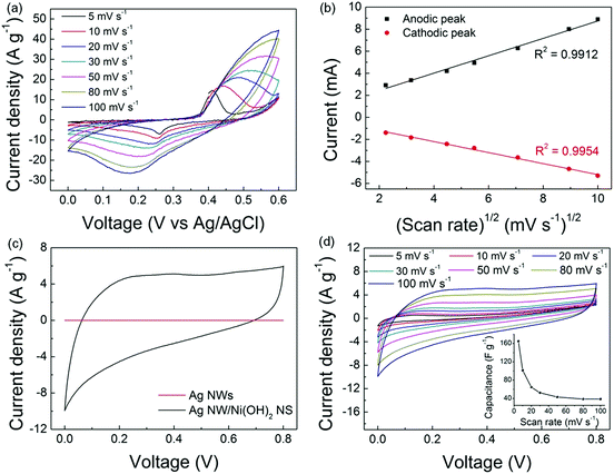
The as-synthesized Ni(OH)2 NSs were dispersed on carbon paper (mass loading: 0.8 mg cm−2) to evaluate their electrochemical performance. As shown in Fig. 5a, the cyclic voltammogram (CV) curves show a pair of redox peaks corresponding to the transition between Ni(OH)2 and NiOOH, indicating that the current response is governed by the faradaic redox reaction. It is known that the electrochemical behaviour can be evaluated by i = aνb,23 in which b ≈ 0.5 corresponds to the semi-infinite linear diffusion controlled current of a battery material, whereas b ≈ 1 corresponds to the surface controlled current of a pseudocapacitor material.24 Here, the linear relationship (Fig. 5b) between the peak current and the square root of the scan rate demonstrates that Ni(OH)2 is a battery-type material. Afterwards, the symmetric all-solid-state supercapacitors were fabricated by assembling the Ag NW/Ni(OH)2 NS composite with PVA/KOH as the solid-state electrolyte, and the CV scan was conducted over a potential window from 0 to 0.8 V. As shown in Fig. 5c, the flattened curve for the Ag NW film indicates that the capacitance of Ag NW is negligible while the Ag NW/Ni(OH)2 NS composite shows a much higher current density, which demonstrates the capacitive contribution of the Ni(OH)2 NSs.
Fig. 5d shows the CV plots of the Ag NW/Ni(OH)2 NS composite at scan rates gradually increasing from 5 to 100 mV s−1. The quasi-rectangular shape of the CV curve is preserved and becomes more obvious with the increasing scan rates, suggesting a fast charge diffusion and stable capacitive performance. Meanwhile, the increased area is a result of the efficient ion diffusion in the polymer electrolyte.25 The specific capacitance can be calculated from the CV curves by using the equation:
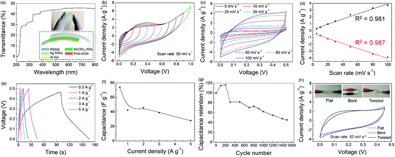
Given that both the Ag NW network and Ni(OH)2 NSs have superior mechanical flexibility, a flexible supercapacitor was fabricated using a similar procedure except that it was transferred onto a PDMS substrate. The Ag NW/Ni(OH)2 NS flexible supercapacitor is semi-transparent because of the transparent nature of the PDMS substrate, as shown by the photograph and the UV-vis spectrum (Fig. 6a). Fig. 6b shows a series of CV measurements of the flexible supercapacitor under different potential windows ranging from 0 to 1 V. It can be seen that the supercapacitive performance is stable, while the large peak current corresponding to the faradaic reaction becomes more obvious with the increasing working potential to 1 V. Similar to the supercapacitor using the glass substrate, the CVs of the flexible device recorded at different scan rates (Fig. 6c) become a more symmetrical rectangular shape without obvious distortion, implying a good reversibility and a fast charge–discharge property. With the increasing scan rates, the current (Fig. 6d) shows a linear response (i–ν), typical of a capacitor.24 Moreover, the supercapacitor performance is characterized by the galvanostatic charge–discharge (GCD) curves at different current densities (Fig. 6e). Unlike EDLCs which possess a linear voltage–time relationship, the asymmetric GCD curve of the Ag NW/Ni(OH)2 NS supercapacitor is indicative of pseudocapacitive behaviour due to the redox reaction.26 Accordingly, the specific capacitance can be calculated by the following equation:
Conclusions
In summary, we have demonstrated a composite based on Ag nanowires (NWs) and Ni(OH)2 nanosheets (NSs) for transparent electrode and all-solid-state supercapacitor applications. The Ni(OH)2 NSs were used not only to infiltrate the empty spaces between the Ag NWs and improve the junction resistance but also to protect the Ag NW network against thermal degradation. As a result, a composite with a sheet resistance of 18.56 Ω □−1, a transmittance of 90.26% as well as an improved thermal stability was successfully prepared after simply coating the Ag NWs with Ni(OH)2 NSs. Moreover, taking the high conductivity of Ag NWs and the pseudocapacitive behaviour of Ni(OH)2 NS into consideration, the Ag NW/Ni(OH)2 NS composite was designed to fabricate an all-solid-state flexible supercapacitor. The supercapacitor device exhibited a good capacitance, moderate cycle stability and flexibility, indicating that the composite could be regarded as a promising candidate for flexible supercapacitors.Conflicts of interest
There are no conflicts to declare.Acknowledgements
This work is funded by the Australian Research Council Project (grant no. FT140100032). The authors would like to thank Dr Yin Yao for assistance with AFM measurements.References
- S. Ye, A. R. Rathmell, Z. Chen, I. E. Stewart and B. J. Wiley, Adv. Mater., 2014, 26, 6670–6687 CrossRef CAS PubMed.
- D. Y. Choi, H. W. Kang, H. J. Sung and S. S. Kim, Nanoscale, 2013, 5, 977–983 RSC.
- R. Chen, S. R. Das, C. Jeong, M. R. Khan, D. B. Janes and M. A. Alam, Adv. Funct. Mater., 2013, 23, 5150–5158 CrossRef CAS.
- K. Zilberberg, F. Gasse, R. Pagui, A. Polywka, A. Behrendt, S. Trost, R. Heiderhoff, P. Görrn and T. Riedl, Adv. Funct. Mater., 2014, 24, 1671–1678 CrossRef CAS.
- H. Sohn, S. Kim, W. Shin, J. M. Lee, H. Lee, D.-J. Yun, K.-S. Moon, I. T. Han, C. Kwak and S.-J. Hwang, ACS Appl. Mater. Interfaces, 2018, 10, 2688–2700 CrossRef CAS PubMed.
- X. Y. Zeng, Q. K. Zhang, R. M. Yu and C. Z. Lu, Adv. Mater., 2010, 22, 4484–4488 CrossRef CAS PubMed.
- Y. Jin, K. Wang, Y. Cheng, Q. Pei, Y. Xu and F. Xiao, ACS Appl. Mater. Interfaces, 2017, 9, 4733–4741 CrossRef CAS PubMed.
- Q. Zhao, M. Zhao, J. Qiu, W. Y. Lai, H. Pang and W. Huang, Small, 2017, 13, 1701091 CrossRef PubMed.
- J.-L. Xu, Y.-H. Liu, X. Gao, Y. Sun, S. Shen, X. Cai, L. Chen and S.-D. Wang, ACS Appl. Mater. Interfaces, 2017, 9, 27649–27656 CrossRef CAS PubMed.
- V. Augustyn, P. Simon and B. Dunn, Energy Environ. Sci., 2014, 7, 1597–1614 RSC.
- H. Wang, H. S. Casalongue, Y. Liang and H. Dai, J. Am. Chem. Soc., 2010, 132, 7472–7477 CrossRef CAS PubMed.
- X. Zhao, X. Ding, Y. Xia, X. Jiao and D. Chen, ACS Appl. Nano Mater., 2018, 1, 1476–1483 CrossRef CAS.
- X. Xiong, D. Ding, D. Chen, G. Waller, Y. Bu, Z. Wang and M. Liu, Nano Energy, 2015, 11, 154–161 CrossRef CAS.
- H. Du, T. Wan, B. Qu, F. Cao, Q. Lin, N. Chen, X. Lin and D. Chu, ACS Appl. Mater. Interfaces, 2017, 9, 20762–20770 CrossRef CAS PubMed.
- M. W. Louie and A. T. Bell, J. Am. Chem. Soc., 2013, 135, 12329–12337 CrossRef CAS PubMed.
- Y. Zhu, C. Cao, S. Tao, W. Chu, Z. Wu and Y. Li, Sci. Rep., 2014, 4, 5787 CrossRef CAS PubMed.
- E. Stathatos, P. Lianos, P. Falaras and A. Siokou, Langmuir, 2000, 16, 2398–2400 CrossRef CAS.
- N. McIntyre and M. Cook, Anal. Chem., 1975, 47, 2208–2213 CrossRef CAS.
- K. Zhang, J. Li, Y. Fang, B. Luo, Y. Zhang, Y. Li, J. Zhou and B. Hu, Nanoscale, 2018, 10, 12981–12990 RSC.
- G. Haacke, J. Appl. Phys., 1976, 47, 4086–4089 CrossRef CAS.
- D. Chen, J. Liang, C. Liu, G. Saldanha, F. Zhao, K. Tong, J. Liu and Q. Pei, Adv. Funct. Mater., 2015, 25, 7512–7520 CrossRef.
- L. Xu, Y.-S. Ding, C.-H. Chen, L. Zhao, C. Rimkus, R. Joesten and S. L. Suib, Chem. Mater., 2008, 20, 308–316 CrossRef CAS.
- H. Lindström, S. Södergren, A. Solbrand, H. Rensmo, J. Hjelm, A. Hagfeldt and S.-E. Lindquist, J. Phys. Chem. B, 1997, 101, 7717–7722 CrossRef.
- V. Augustyn, J. Come, M. A. Lowe, J. W. Kim, P.-L. Taberna, S. H. Tolbert, H. D. Abruña, P. Simon and B. Dunn, Nat. Mater., 2013, 12, 518 CrossRef CAS PubMed.
- W. Xiong, X. Hu, X. Wu, Y. Zeng, B. Wang, G. He and Z. Zhu, J. Mater. Chem. A, 2015, 3, 17209–17216 RSC.
- J. Liu, L. Zhang, H. B. Wu, J. Lin, Z. Shen and X. W. D. Lou, Energy Environ. Sci., 2014, 7, 3709–3719 RSC.
- W. Liu, X. Li, M. Zhu and X. He, J. Power Sources, 2015, 282, 179–186 CrossRef CAS.
- T. Gu and B. Wei, J. Mater. Chem. A, 2016, 4, 12289–12295 RSC.
- J. Zhang, S. Liu, G. Pan, G. Li and X. Gao, J. Mater. Chem. A, 2014, 2, 1524–1529 RSC.
Footnote |
| † Electronic supplementary information (ESI) available. See DOI: 10.1039/c8na00110c |
| This journal is © The Royal Society of Chemistry 2019 |

