DOI:
10.1039/C8SC02110D
(Edge Article)
Chem. Sci., 2018,
9, 6080-6084
Synergistically mediated enhancement of cathodic and anodic electrochemiluminescence of graphene quantum dots through chemical and electrochemical reactions of coreactants †
Received
13th May 2018
, Accepted 17th June 2018
First published on 18th June 2018
Abstract
We for the first time propose a new concept where a greater enhancement in dual potential electrochemiluminescence (ECL) of a single graphene quantum dot (GQD) emitter can be achieved through the coupling between chemical and electrochemical reactions of two different coreactants of K2S2O8 and Na2SO3.
Introduction
Electrogenerated chemiluminescence (ECL) is the process in which electrogenerated species undergo high-energy electron-transfer reactions to form excited species that emit light.1 ECL sensors have many advantages, such as a low background optical signal, being potential- and spatial-controlled, low cost, wide range of analytes, and high sensitivity.2 Thus, the ECL technique has been extensively used in bioanalytical fields such as immunoassays3 and DNA analysis.4 Generally, only one emission signal change is observed in the conventional ECL methods. False positives or false negatives may occur due to other interferences, especially in a complex biological matrix. Therefore, it is imperative to develop an efficient ECL system which can eliminate the aforementioned problems of false positives or false negatives. Recently, a ratiometric ECL method has attracted increasing attention because it can effectively restrain the signal interference by self-calibration of two emission signals and make the obtained results more convincing.5 In the case of ratiometric ECL schemes, two different ECL emitter units are usually needed. For example, Zhang et al. employed a CdS nanocrystal and luminol as the two ECL emitters to detect DNA.6 Zhao et al. reported an ECL ratiometric strategy for highly sensitive detection of protein kinase activity using graphene quantum dots (GQDs) and luminol as the emitters.7 However, no reports focus on the synchronous cathodic and anodic ECL of one emitter. In this work, we propose dual ECL based on a single GQD emitter for the first time.
In the development of the ECL history, traditional ECL emitters such as Ru(bpy)32+, luminol and their derivatives have been widely studied. Since the ECL properties of quantum dots (QDs) were first reported in 2002,8 extensive fundamental research and analytical applications of the ECL of QDs, especially semiconductor-based quantum dots, have been developed.9 However, the semiconductor-based QDs raise serious health and environmental concerns because of the inherent toxicity of heavy metals. Graphene quantum dots (GQDs), smaller than 100 nm in few layers (less than 10),10 are a new kind of zero-dimensional carbon nanomaterial. GQDs exhibit obvious advantages over traditional QDs, such as low cytotoxicity and attractive biocompatibility.11 Thus, GQDs are expected to have wide application in ECL research.12 To date, the cathodic ECL of GQDs has been widely investigated, but little work has been reported on the anodic ECL of GQDs because of the weak or unstable signals.
To the best of our knowledge, in this work, we find for the first time that a greater ECL enhancement at both the anode and cathode can be achieved using the strategy of chemical and electrochemical co-mediation. To be more specific, we develop dual potential ECL using one GQD emitter and two different coreactants of K2S2O8 and Na2SO3. The strategy of using two different coreactants, though not common, was already reported, such as the use of S2O82− and O2 for ultrasensitive biosensing.13 Nonetheless, this study still cannot realize ECL enhancement at both electrodes. The as-resulted dual potential ECL in our work exhibits outstanding enhancement for both cathodic and anodic processes. The corresponding ECL enhancement mechanism has been investigated in detail. On the basis of the new dual-potential ECL system, we construct an ECL immunosensor which can detect HIgG with appreciable sensitivity.
Results and discussion
GQDs were synthesized via a chemical oxidation method illustrated in Scheme S1A.† As shown in the TEM image (Fig. S1A†), the as-prepared GQDs are uniformly dispersed without agglomeration. A well-defined lattice fringe with a spacing of 0.21 nm is clearly observed in the inset of Fig. S1A,† which is similar to those reported previously.14 The diameter is mainly distributed in the range of 0.5–4 nm with an average diameter of 2.5 nm (Fig. S1B†). In addition, the as-synthesized GQDs have thicknesses of 1–2 nm from the observation of AFM characterization (shown in Fig. S2†). The FTIR spectrum (Fig. S1C†) indicates the presence of an –OH group at 3370 cm−1, a C![[double bond, length as m-dash]](https://www.rsc.org/images/entities/char_e001.gif) O group at 1622 cm−1, a C–O (alkoxy) group at 1137 cm−1 and a C–O (carboxy) group at 1425 cm−1. The absorptions below 1137 cm−1 should be attributed to the out-of-plane bending of ring C–H bonds and out-of-plane ring bending. Fig. S1D† shows the photoluminescence (PL) spectra and UV-vis absorption spectra of the GQDs. In the UV-vis absorption spectrum, a broad absorption band at 360 nm appears, which is ascribed to the n–π* transition of C
O group at 1622 cm−1, a C–O (alkoxy) group at 1137 cm−1 and a C–O (carboxy) group at 1425 cm−1. The absorptions below 1137 cm−1 should be attributed to the out-of-plane bending of ring C–H bonds and out-of-plane ring bending. Fig. S1D† shows the photoluminescence (PL) spectra and UV-vis absorption spectra of the GQDs. In the UV-vis absorption spectrum, a broad absorption band at 360 nm appears, which is ascribed to the n–π* transition of C![[double bond, length as m-dash]](https://www.rsc.org/images/entities/char_e001.gif) O. The strong background absorption below 300 nm is related to the electron transitions from π to π* of aromatic sp2 domains.15 The GQD aqueous dispersion is transparent under daylight, while it exhibits greenish yellow fluorescence under an irradiation with a 365 nm UV lamp as shown in the inset of Fig. S1D.† The emission spectra at different excitation wavelengths show that the maximum emission wavelength becomes red-shifted with increasing excitation wavelength. Similar to previous reports,11 GQDs exhibits an excitation-dependent PL property.
O. The strong background absorption below 300 nm is related to the electron transitions from π to π* of aromatic sp2 domains.15 The GQD aqueous dispersion is transparent under daylight, while it exhibits greenish yellow fluorescence under an irradiation with a 365 nm UV lamp as shown in the inset of Fig. S1D.† The emission spectra at different excitation wavelengths show that the maximum emission wavelength becomes red-shifted with increasing excitation wavelength. Similar to previous reports,11 GQDs exhibits an excitation-dependent PL property.
The ECL and cyclic voltammograms (CVs) of four different systems of (a) GQDs/ITO in a solution of Na2SO3 (GQDs–Na2SO3), (b) ITO in a solution of Na2SO3–K2S2O8 (Na2SO3–K2S2O8), (c) GQDs/ITO in a solution of K2S2O8 (GQDs–K2S2O8), and (d) GQDs/ITO in a solution of K2S2O8–Na2SO3 (GQDs–K2S2O8–Na2SO3) were studied. ITO was used as the working electrode due to its good conductivity as well as optical transparency that allows more generated light to be detected. When the potential is positively scanned from −1.2 V to 1.5 V with an initial potential of 0 V, the GQDs–Na2SO3 system does not show obvious anodic and cathodic ECL emissions (Fig. 1A, curve a). Similarly, the Na2SO3–K2S2O8 system exhibits only very weak anodic and cathodic ECL emissions (Fig. 1A, curve b), indicating that the K2S2O8–Na2SO3 system has only very limited contribution to the ECL intensity if GQDs are not present. In contrast, the GQD modified electrode in a solution of K2S2O8 displays a prominent cathodic ECL signal while the anodic ECL is yet invisible (Fig. 1A, curve c). When adding Na2SO3 to the GQDs–K2S2O8 system, both the anodic and cathodic ECL signals are significantly increased (Fig. 1A, curve d). The ECL-time profiles of these four systems are shown in Fig. S3.† As shown in the corresponding CVs in Fig. 1B, an anodic peak around 1.4 V appears in the system containing Na2SO3. This peak can be attributed to the oxidation of Na2SO3. In contrast, a reduction current of K2S2O8 appears in the case of the systems (curves b–d) containing K2S2O8 regardless of the presence of GQDs. The ECL spectra of GQDs at cathodic and anodic potentials are shown in Fig. 1C and D, respectively. They show that the ECL emission peaks appear at 509 nm at the anodic potentials and 503 nm at the cathodic potentials. Both the ECL peak positions are close to the PL emission peak wavelength of 525 nm (excited at 370 nm) for GQDs, revealing that the ECL signals indeed originated from GQDs. Additional results demonstrate that the ECL system is very stable as evidenced by the invariable anodic and cathodic ECL signals during continuous cyclic potential scans in PBS (Fig. 2A). The relative standard deviations (RSD) for the anodic and cathodic ECLs are 1.5% and 1.2%, respectively. Note that we can observe a very slight signal of the GQDs–K2S2O8–Na2SO3 system (red line) compared to others in the potential range of −0.75 V to 0.75 V where there is no ECL occurring, indicating that SO4˙− and SO3˙− can produce chemiluminescence with GQDs, but its intensity is negligible compared with the ECL signal.
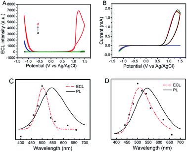 |
| | Fig. 1 ECL-potential curves (A) and corresponding cyclic voltammograms (B) of GQDs–100 mM Na2SO3 (black lines), GQDs–10 mM K2S2O8 (blue lines), 100 mM Na2SO3–10 mM K2S2O8 (green lines), and GQDs–10 mM K2S2O8–100 mM Na2SO3 (red lines) in a 0.1 M air-saturated PBS (pH 7.4) at a scan rate of 0.2 V s−1. (C) PL (λex = 370 nm) (black lines) and ECL spectra (red lines) for the GQDs–10 mM K2S2O8–100 mM Na2SO3 system at cathodic (C) and anodic potentials (D), respectively. | |
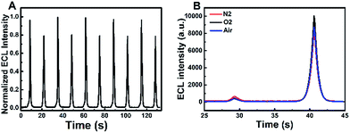 |
| | Fig. 2 (A) Continuous ECL responses of the GQDs–K2S2O8–Na2SO3 system during a continuous potential scan between −1.2 and 1.5 V at a scan rate of 0.2 V s−1 (B) ECL-time profiles of the GQDs–K2S2O8–Na2SO3 system in air-saturated (blue curve), nitrogen-saturated (red curve) and oxygen-saturated (black curve) 0.1 M PBS (pH 7.4) (scan potential: −1.2 to 1.0 V). | |
Mechanism of cathodic ECL
As previously mentioned, an obvious cathodic ECL appears in the GQDs–K2S2O8 system. This cathodic ECL behavior of GQDs is similar to previous reports.2c,12a The electrochemical reduction of K2S2O8 and GQDs at negative potentials generates SO4˙− and GQDs˙− radicals, respectively. The strongly oxidizing SO4˙− radicals can react with GQDs˙− radicals via electron-transfer annihilation, generating an excited state (GQDs*) which eventually produces an ECL emission. When Na2SO3 is added to the GQDs–K2S2O8 system, the intensity of cathodic ECL is significantly enhanced (refer to curves c and d in Fig. 1A). This enhancement can be understood by the fact that additional SO4˙− radicals are generated chemically by the reaction between Na2SO3 and K2S2O8 in addition to those generated electrochemically, and thus, the cathodic ECL intensity will be considerably increased if enough GQDs˙− radicals are present. This implies that the electrochemical formation rate of GQDs˙− radicals is much higher than the electrochemical formation rate for SO4˙− radicals. The possible ECL mechanism could be expressed using the following reactions (1)–(5).| | | S2O82− + e−→ SO42− + SO4˙− | (2) |
| | | SO32− + S2O82− → SO4˙− + SO3˙− + SO42− | (3) |
| | | GQDs˙− + SO4˙− → GQDs* + SO42− | (4) |
Mechanism of anodic ECL
According to the literature,15 sulfite acts as a coreactant which can enhance the anodic ECL of CdTe QDs in air-saturated aqueous solution. However, no literature reported that Na2SO3 can enhance the anodic ECL of GQDs. Fig. 1A shows that only a very weak anodic signal is observed in the GQD–Na2SO3 system (Fig. 1A, curve a), and no anodic ECL in the GQD–K2S2O8 system (Fig. 1A, curve c) appears. However, when K2S2O8 is introduced to the GQDs–Na2SO3 system, a great enhancement of the anodic ECL is observed. This result indicates that dual coreactants could exhibit synergy in the ECL emission of GQDs. As is well known, SO3˙− and SO4˙− radicals are produced by the chemical reaction of S2O82− and SO32−. However, the fact that O2˙− is considered as an important species for the enhancement of anodic ECL in previous studies16,17 should be considered. Therefore, to confirm whether the synergistic effect is the cause of the anodic ECL of GQDs, the influence of dissolved oxygen (DO) is examined in control experiments in a potential ranging from −1.2 to +1.0 V. In this potential window, the electrogeneration of O2 at high potentials can be avoided. Fig. 2B clearly shows that there is no obvious change in the anodic ECL intensity in air as compared to that in nitrogen-saturated aqueous solution. If additional oxygen is bubbled into the system, the increase in anodic ECL signal is still negligible. These results demonstrate that the influence of dissolved oxygen on the anodic ECL response can be ignored. Therefore, O2˙− should not be a key species for the enhanced anodic ECL.
Based on the above experimental results, we proposed a possible anodic mechanism. The electrochemical oxidation of Na2SO3 and GQDs at positive potentials generates SO3˙− and GQDs˙+ radicals, respectively. SO3˙− radicals can react with GQDs˙+ radicals via electron-transfer annihilation, generating an excited state (GQDs*) which eventually produces an ECL emission. Since most of the Na2SO3 is directly oxidized to Na2SO4, the amount of SO3˙− produced by the electrochemical oxidation is very limited, therefore the anodic ECL signal of the GQDs–Na2SO3 system is very weak. As mentioned above, SO3˙− radicals can be created from the chemical reaction between K2S2O8 and Na2SO3. When K2S2O8 is added to the GQDs–Na2SO3 system, the amount of SO3˙− radicals generated is much more than that produced from electrochemical pathways, and the corresponding anodic ECL is increased significantly. Meanwhile, in air-saturated aqueous solution, SO3˙− can combine with oxygen and yield an O3SOO˙− anionic radical. In this case, two possible auto-catalytic propagation steps are followed:17b,d (1) the generated O3SOO˙− radicals react with SO32− to produce SO4˙− radicals; (2) the generated SO4˙− radicals react with SO32− to yield SO3˙− radicals. As a result, oxygen will not show obvious influence on the anodic ECL of GQDs, which is consistent with the experimental results. Furthermore, electron paramagnetic resonance (EPR) was recorded to identify the radicals in the system. Fig. 3A shows the hyperfine splitting constants of 5, 5-dimethyl-1-pyrroline N-oxide (DMPO) radical adducts. The hyperfine splitting constants αN = 14.5 G, αHβ = 16.2 G are representative of DMPO–SO3, verifying the existence of SO3˙− in the system. Meanwhile, DMPO–SO4 signal with αN = 13.6 G, αHβ = 10.5 G, and αHγ = 1.42 G is observed, which confirms the formation of SO4˙−. The results indicate that both SO3˙− and SO4˙− radicals exist in the K2S2O8–Na2SO3 system. The amounts of SO3˙− radicals formed chemically and electrochemically were also investigated by using EPR spectra. Fig. 3B shows that the amount of SO3˙− radicals generated by electrochemical oxidation is very low, while that produced by chemical reaction is enhanced about 47-fold. The effects of K2S2O8 and Na2SO3 concentrations on the ECL enhancement of GQDs were investigated. As shown in Fig. S4,† the anodic ECL intensity of GQDs increases with the increase of K2S2O8 concentration. The corresponding EPR spectra were recorded. Fig. S5† shows the EPR spectra of different systems. Setting the concentration of Na2SO3 at 0.1 M, with the increase of K2S2O8 concentration, both the EPR signals of DMPO–SO3 and DMPO–SO4 increase, which verifies that the anodic ECL signal increases with increased SO3˙− radicals.
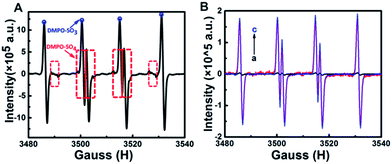 |
| | Fig. 3 (A) EPR spectrum of K2S2O8–Na2SO3–DMPO. (B) (a) EPR spectrum of DMPO–0.1 M Na2SO3 in a cyclic potential scan from 0 to 1.5 V. (b) EPR spectrum of DMPO–0.1 M Na2SO3–0.01 M K2S2O8. (c) EPR spectrum of DMPO–0.1 M Na2SO3–0.01 M K2S2O8 in a cyclic potential scan from 0 to 1.5 V. | |
In view of the above discussion, a possible anodic ECL mechanism can be proposed for the GQDs–Na2SO3–K2S2O8 system. As shown in Scheme 1, SO3˙− radicals can be generated by both chemical and electrochemical reactions. The electrochemical oxidation of GQDs at positive potentials produces GQDs˙+ radicals. SO3˙− radicals can react with GQDs˙+ radicals via electron-transfer annihilation, generating an excited state (GQDs*) which eventually produces an ECL emission. SO3˙− radicals are the key species in this process. The possible ECL mechanism could be expressed using the following reactions (6)–(10).
| | | SO32− + S2O82− → SO4˙− + SO3˙− + SO42− | (8) |
| | | GQDs˙+ + SO3˙−→ GQDs* + SO3 | (9) |
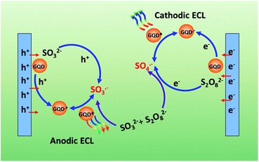 |
| | Scheme 1 Schematic illustration of the ECL mechanism of GQDs. | |
On the basis of the remarkably enhanced anodic and cathodic ECL signals of the GQDs–K2S2O8–Na2SO3 system, an immunosensor was constructed to detect different concentrations of HIgG(Ag) as illustrated in Scheme S1B† (for experimental details refer the Experimental section). The electrochemical impedance spectra (EIS) results in Fig. S6† indicate that the immunosensor has been fabricated successfully. As shown in Fig. 4A, the ECL emission in the presence of HIgG (b–i) is lower than that in the absence of HIgG (a), and the ECL intensity decreases gradually with increasing the concentrations of HIgG. This decrease in ECL signal can be ascribed to the inhibited access of the coreactants and the chemically generated radicals to the electrode surface due to the steric hindrance, which is caused by the formed immune complex from specific binding between the antigen and antibody. Both the responses in cathodic ECL and anodic ECL can be used to confirm the detection of HIgG. The standard calibration curve for the HIgG detection is displayed in Fig. 4B. The logarithmic value of anodic/cathodic ECL linearly depends on the logarithm of the HIgG concentration in a range of 0.1–150 ng mL−1 with a detection limit of 0.02 ng mL−1 (S/N = 3). This immunosensor outperforms the commercially available ELISA-based IgG sensors which have a minimum detection limit of 0.06 μg mL−1.
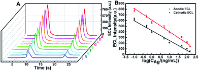 |
| | Fig. 4 (A) ECL-time profiles of the electrode at different concentrations of Ag (a–i: 0, 0.1, 0.5, 1, 5, 10, 50.0, 100.0 and 150.0 ng mL−1). (B) Relationship between ECLanodevs. log![[thin space (1/6-em)]](https://www.rsc.org/images/entities/char_2009.gif) CAg (red line) and ECLcathodicvs. log CAg (red line) and ECLcathodicvs. log![[thin space (1/6-em)]](https://www.rsc.org/images/entities/char_2009.gif) CAg (black line). CAg (black line). | |
In conclusion, we present a new concept of coupling chemical and electrochemical reactions together for ECL enhancement on the anode and cathode. That is completely different from conventional ECL enhancement systems available to date. In the experiments, dual potential ECL using one GQD emitter and two different coreactants of K2S2O8 and Na2SO3 is proposed, and the corresponding mechanism is investigated. Furthermore, an ECL immunosensor for the sensitive detection of human IgG (HIgG) has been developed based on this new dual-potential ECL. The newly proposed strategy is simple, efficient, and economic to achieve the synchronous ECL enhancement in dual electrodes, which would be promising for the construction of ECL biosensors.
Experimental Section
Preparation of GQDs
GQDs were synthesized by a chemical oxidation method. In brief, a GO solution (30 mL, 0.5 mg mL−1) was first added to a mixture of concentrated H2SO4 (2 mL) and HNO3 (8 mL). Then, the mixture was refluxed at 150 °C for 18 h. The obtained product consisted of a brown transparent suspension. After cooling to room temperature, the pH value of the suspension was adjusted to 8 using NaOH (1 M) aqueous solution carefully. The suspension was then filtered through a 0.22 μm microporous membrane to remove the black precipitates. Finally, the resulting solution was dialyzed in a dialysis bag (retained molecular weight: 500 Da) to yield GQDs.
Fabrication of an ECL immunosensor
ITO glass was cleaned by immersion in 2 M boiling KOH solution dissolved in ethanol for 15 min, followed by washing thoroughly with water and dried under nitrogen. Then, a 15 mL GQD solution was dropped onto the cleaned ITO electrode. After drying naturally, a 15 μL 0.05% chitosan solution was added to stabilize GQDs as well as to facilitate the adsorption of protein molecules. The modified electrode was then allowed to dry in air. After the electrode was washed with abundant ultrapure water, it was incubated with 2.0% glutaraldehyde for 2 h, followed by dropping 50 μg mL−1 antibody solution (10 mM PBS, pH 7.4) onto the electrode surface and incubated at 4 °C for at least 12 h. After washing with pH 7.4 PBS, the electrode was incubated in 30 μL of 5 wt% BSA for 1 h to avoid possible non-specific adsorption. After washing, the ECL immunosensor was obtained. Finally, the modified electrode was dipped in the target antigen sample for 1 h, followed by rinsing with PBS.
Conflicts of interest
There are no conflicts to declare.
Acknowledgements
This work was supported by grants from the National Natural Science Foundation of China (21327902, 21635004, 21675079).
References
- W. Miao, Chem. Rev., 2008, 108, 2506 CrossRef PubMed.
-
(a) J. Li, F. N. Xiao and X.H Xia, Analyst, 2012, 137, 5245 RSC;
(b) Y. L. Chang, R. E. Palacios, F. R. F. Fan, A. J. Bard and P. F. Barbara, J. Am. Chem. Soc., 2008, 130, 8906 CrossRef PubMed;
(c) L. Zheng, Y. Chi, Y. Dong, J. Lin and B. Wang, J. Am. Chem. Soc., 2009, 131, 4564 CrossRef PubMed;
(d) Z. Chen, L. Zhang, Y. Liu and J. Li, J. Electroanal. Chem., 2016, 781, 83 CrossRef.
- F. N. Xiao, M. Wang, F. B. Wang and X. H. Xia, Small, 2014, 10, 706 CrossRef PubMed.
- Q. Lu, W. Wei, Z. Zhou, Z. Zhou, Y. Zhang and S. Liu, Analyst, 2014, 139, 2404 RSC.
- Y. He, J. Li and Y. Liu, Anal. Chem., 2015, 87, 9777 CrossRef PubMed.
- H. R. Zhang, J. J. Xu and H. Y. Chen, Anal. Chem., 2013, 85, 5321 CrossRef PubMed.
- H. F. Zhao, R. P. Liang, J. W. Wang and J. D. Qiu, Chem. Commun., 2015, 51, 12669 RSC.
- Z. Ding, B. M. Quinn, S. K. Haram, L. E. Pell, B. A. Korgel and A. J. Bard, Science, 2002, 296, 1293 CrossRef PubMed.
-
(a) N. Myung, Z. Ding and A. Bard, J. Nanosci. Lett., 2002, 2, 1315 CrossRef;
(b) L. Dennany, M. Gerlach, S. O'Carroll, T. E. Keyes, R. J. Forster and P. Bertoncello, J. Mater. Chem., 2011, 21, 13984 RSC;
(c) L. Sun, L. Bao, B. R. Hyun, A. C. Bartnik, Y. W. Zhong, J. C. Reed, D. W. Pang, H. D. Abruña, G. G. Malliaras and F. W. Wise, Nano Lett., 2009, 9, 789 CrossRef PubMed.
- L. Cao, X. Wang, M. J. Meziani, F. Lu, H. Wang, P. G. Luo, Y. Lin, B. A. Harruff, L. M. Veca, D. Murray, S. Y. Xie and Y. P. Sun, J. Am. Chem. Soc., 2007, 129, 11318 CrossRef PubMed.
- Q. Xu, Q. Zhou, Z. Hua, Q. Xue, C. Zhang, X. Wang, D. Pan and M. Xiao, ACS Nano, 2013, 7, 10654 CrossRef PubMed.
-
(a) Y. Yan, Q. Liu, H. Mao and K. Wang, J. Electroanal. Chem., 2016, 775, 1 CrossRef;
(b) C. Wang, J. Qian, K. Wang, M. Hua, Q. Liu, N. Hao, T. You and X. Huang, ACS Appl. Mater. Interfaces, 2015, 7, 26865 CrossRef PubMed;
(c) J. Lou, S. Liu, W. Tu and Z. Dai, Anal. Chem., 2015, 87, 1145 CrossRef PubMed.
- M. Zhao, Y. Zhuo, Y. Chai, Y. Xiang, N. Liao, G. Gui and R. Yuan, Analyst, 2013, 138, 6639 RSC.
- S. Stankovich, D. A. Dikin, G. H. Dommett, K. M. Kohlhaas, E. J. Zimney, E. A. Stach, R. D. Piner, S. T. Nguyen and R. S. Ruoff, Nature, 2006, 442, 282 CrossRef PubMed.
- D. Pan, J. Zhang, Z. Li and M. Wu, Adv. Mater., 2010, 22, 734 CrossRef PubMed.
- X. Liu and H. Ju, Anal. Chem., 2008, 80, 5377 CrossRef PubMed.
-
(a) W. Xue, Z. Lin, H. Chen, C. Lu and J. M. Lin, J. Phys. Chem. C, 2011, 115, 21707 CrossRef;
(b) C. Mottley and R. P. Mason, Arch. Biochem. Biophys., 1988, 267, 681 CrossRef PubMed;
(c) N. Lian, H. Zhao, C. Sun, S. Chen, Y. Lu and L. Jin, Microchem. J., 2003, 74, 223 CrossRef;
(d) E. Hayon, A. Treinin and J. Wilf, J. Am. Chem. Soc., 1972, 94, 47 CrossRef.
Footnotes |
| † Electronic supplementary information (ESI) available. See DOI: 10.1039/c8sc02110d |
| ‡ These authors contributed equally to this work. |
|
| This journal is © The Royal Society of Chemistry 2018 |
Click here to see how this site uses Cookies. View our privacy policy here.  Open Access Article
 *b and
Xing-Hua
Xia
 *a
*a
![[double bond, length as m-dash]](https://www.rsc.org/images/entities/char_e001.gif) O group at 1622 cm−1, a C–O (alkoxy) group at 1137 cm−1 and a C–O (carboxy) group at 1425 cm−1. The absorptions below 1137 cm−1 should be attributed to the out-of-plane bending of ring C–H bonds and out-of-plane ring bending. Fig. S1D† shows the photoluminescence (PL) spectra and UV-vis absorption spectra of the GQDs. In the UV-vis absorption spectrum, a broad absorption band at 360 nm appears, which is ascribed to the n–π* transition of C
O group at 1622 cm−1, a C–O (alkoxy) group at 1137 cm−1 and a C–O (carboxy) group at 1425 cm−1. The absorptions below 1137 cm−1 should be attributed to the out-of-plane bending of ring C–H bonds and out-of-plane ring bending. Fig. S1D† shows the photoluminescence (PL) spectra and UV-vis absorption spectra of the GQDs. In the UV-vis absorption spectrum, a broad absorption band at 360 nm appears, which is ascribed to the n–π* transition of C![[double bond, length as m-dash]](https://www.rsc.org/images/entities/char_e001.gif) O. The strong background absorption below 300 nm is related to the electron transitions from π to π* of aromatic sp2 domains.15 The GQD aqueous dispersion is transparent under daylight, while it exhibits greenish yellow fluorescence under an irradiation with a 365 nm UV lamp as shown in the inset of Fig. S1D.† The emission spectra at different excitation wavelengths show that the maximum emission wavelength becomes red-shifted with increasing excitation wavelength. Similar to previous reports,11 GQDs exhibits an excitation-dependent PL property.
O. The strong background absorption below 300 nm is related to the electron transitions from π to π* of aromatic sp2 domains.15 The GQD aqueous dispersion is transparent under daylight, while it exhibits greenish yellow fluorescence under an irradiation with a 365 nm UV lamp as shown in the inset of Fig. S1D.† The emission spectra at different excitation wavelengths show that the maximum emission wavelength becomes red-shifted with increasing excitation wavelength. Similar to previous reports,11 GQDs exhibits an excitation-dependent PL property.


![[thin space (1/6-em)]](https://www.rsc.org/images/entities/char_2009.gif)