 Open Access Article
Layered manganese-based metal–organic framework as a high capacity electrode material for supercapacitors†
Xianmei Wanga,
Xiuxiu Liua,
Hongren Ronga,
Yidan Songa,
Hao Wena and
Qi Liu *ab
*ab
aSchool of Petrochemical Engineering, Jiangsu Key Laboratory of Advanced Catalytic Materials and Technology, Advanced Catalysis and Green Manufacturing Collaborative Innovation Center, Changzhou University, Changzhou, Jiangsu 213164, P. R. China. E-mail: liuqi62@163.com
bState Key Laboratory of Coordination Chemistry, Nanjing University, Nanjing, Jiangsu 210093, P. R. China
First published on 7th June 2017
Abstract
For the development of supercapacitors with higher energy densities, metal–organic frameworks (MOFs), as electrode materials for supercapacitors, have attracted much attention. Herein, layered manganese-based MOF ([Mn(tfbdc)(4,4′-bpy)(H2O)2], Mn-LMOF; H2tfbdc = 2,3,5,6-tetrafluoroterephthalic acid, 4,4′-bpy = 4,4′-bipyridine) was synthesized by a simple solution reaction and evaluated as an electrode material for supercapacitors for the first time. The Mn-LMOF electrode showed a high specific capacitance, a good cycling stability and a improved rate capability. Its maximum specific capacitances were 1098 F g−1 for 1 M KOH and 1178 F g−1 for 1 M LiOH solutions at a current density of 1 A g−1. The specific capacitance retention was maintained at 92.6% after 2000 cycles in 1 M KOH, slightly lower than that in 1 M LiOH. The excellent supercapacitive performance may be ascribed to the nature of Mn-LMOF, containing a layered structure and nano-sized particles.
Introduction
With the rapid development of the world economy, mankind is facing more and more problems, such as the depletion of fossil fuels and serious environmental pollution. Therefore, green and sustainable energy is one of the 21st century's most important issues. The supercapacitor, as a type of electrochemical energy storage and conversion device, that has the advantages of high power density, long cycle life and high discharge efficiency has attracted great attention.1–4 It is well known that the electrode material of RuO2 has good pseudocapacitance,5 but its cost is too high owing to the fact that the metal Ru is a scarce resource. As a result, researchers hope to find inexpensive electrode materials. Compared with RuO2, manganese oxides MnOx (MnO, Mn3O4, Mn2O3, MnO2), are much cheaper, more abundant on Earth, and have environmentally friendly and widespread potential applications; hence they are considered to be promising electrode materials for supercapacitors.6 To date, various pure MnOx have been directly used as electrode materials.7–10 However, the poor electrical conductivities of these materials often result in weak stabilities and lower capacitances. To overcome this disadvantage, one route is to make hybrid composites by combining pure MnOx and carbon materials, other metal oxides and conducting polymers.11–13 The other is to design and synthesize new Mn-based electrode materials with high capacitance. Compared with that of pure MnOx, electrical conductivities of the hybrid composites were enhanced, but some new shortages, such as increase of inherent contact resistances, structural instability and decrease of capacitance appeared at the same time. Therefore, to solve these problems, it is necessary to use the route of preparing new Mn-based electrode materials with high capacitance.Metal–organic frameworks (MOFs), as a class of porous coordination polymer materials,14,15 have the advantages of high specific surface area, adjustable pore size, open metal sites and regular structure. Based on these advantages, they have potential applications in various fields, such as catalysis,16–18 gas capture and release,19,20 imaging and sensing,21,22 batteries,23–25 and magnetic materials.26 In recent years, the application research of MOFs in supercapacitors has seen rapid development.27–30 MOFs used as electrode materials of supercapacitors can be mainly ascribed to two major cases. In one case, MOFs are used as templates for synthesizing porous metal oxides, carbon or metal oxide/carbon composites.31,32 In the other case, pristine MOFs can directly act as electrode materials for supercapacitors, owing to their tunable pore size and metal ions with redox activity.33–57 To the best of our knowledge, in 2012, Díaz et al. first reported that Co8-MOF-5(Zn3.68Co0.32O(BDC)3(DEF)0.75) can be directly used as the electrode material of supercapacitors;33 in the same year, a Co-based MOF with three-dimensional (3D) structure was investigated by Lee et al. as an electrode material for supercapacitors, which displayed a specific capacitance of 206 F g−1 in LiOH solution.34 Subsequently, dozens of MOF-based supercapacitor electrode materials have been reported in the past few years, such as, Co-based MOF,35–39 zirconium-based MOF,40,41 Zn-based MOF,42 and Ni-based MOF.43–51 It is worthwhile to point out that our and Wei's groups have recently verified that two-dimensional (2D) layered MOFs can serve as high performance supercapacitor electrode materials. For example, in 2014, Wei et al. reported that a layered Ni-MOF can be used as a supercapacitor electrode material. This material showed a specific capacitance of 1127 F g−1 in KOH solution, an excellent cycling stability and a high rate capability.43 After Zn doping, the as-synthesized Zn-doped Ni-MOF exhibited an improved performance.44 In 2015, we reported the synthesis of a layered Cu-MOF and investigated its capacitive behavior, which displayed a high specific capacitance of 1274 F g−1 in LiOH solution.54 Subsequently, we evaluated a layered Co-MOF as a supercapacitor electrode material. This material can deliver a maximum specific capacitance of 2474 F g−1 at 1 A g−1.38 In addition, Ni-MOF/carbon nanotube (CNT) composites were synthesized by Wen et al., which exhibited a better performance.47 Very recently, layered structural Co-MOF nanosheets were investigated by Wei et al. as an electrode material for supercapacitors, which showed a maximum specific capacitance of 2564 F g−1 at 1 A g−1.39 Dinǎ et al. utilized a layered, conductive Ni-MOF as an electrode material for supercapacitors. An areal capacitance of 18 mF cm−2 and capacity retention greater than 90% over 10![[thin space (1/6-em)]](https://www.rsc.org/images/entities/char_2009.gif) 000 cycles can be obtained in the conductive Ni-MOF-based device. In particular, this is the first example of a supercapacitor made entirely from neat MOFs as active materials, without conductive additives or other binders.50 The excellent electrochemical properties of these 2D layered MOF materials should be related to their sufficient interlayer spaces and redox-activity metal ions. Though some MOF-based supercapacitor electrode materials with high performances have been obtained, such materials are not yet present in large numbers. Specifically, layered Mn-based MOFs used as electrode materials for supercapacitors have not been reported.
000 cycles can be obtained in the conductive Ni-MOF-based device. In particular, this is the first example of a supercapacitor made entirely from neat MOFs as active materials, without conductive additives or other binders.50 The excellent electrochemical properties of these 2D layered MOF materials should be related to their sufficient interlayer spaces and redox-activity metal ions. Though some MOF-based supercapacitor electrode materials with high performances have been obtained, such materials are not yet present in large numbers. Specifically, layered Mn-based MOFs used as electrode materials for supercapacitors have not been reported.
In the present study, we successfully synthesized a layered Mn-based MOF ([Mn(tfbdc)(4,4′-bpy)(H2O)2], Mn-LMOF; H2tfbdc = 2,3,5,6-tetrafluoroterephthalic acid, 4,4′-bpy = 4,4′-bipyridine) and investigated its electrochemical performances as an electrode material for supercapacitors for the first time. The Mn-LMOF electrodes displayed a high specific capacitance, a good cycling stability and an improved rate capability. Specific capacitances of 1098 and 1178 F g−1 were achieved in 1 M KOH and 1 M LiOH solution for the Mn-LMOF.
Experimental
Materials synthesis
Mn-LMOF was synthesized according to a previous report with some modifications.24 Moreover, 4,4′-bpy (0.0156 g, 0.10 mmol) and H2tfbdc (0.0476 g, 0.20 mmol) were dissolved in 10 mL water with stirring. Then, a 10 mL water solution of Mn(OAc)2·4H2O (0.049 g, 0.20 mmol) was mixed with the above solution to obtain a colorless solution. This solution was allowed to stand at room temperature for evaporation, and colorless crystals of [Mn(tfbdc)(4,4′-bpy)(H2O)2] (Mn-LMOF) were collected after a few days.Material characterization
Powder X-ray diffraction (XRD) patterns were recorded on an X-ray diffractometer (D/max2500 PC, Rigaku) using Cu-Kα radiation (1.5406 Å). Fourier-transform infrared (FT-IR) spectral measurements were carried out on a Nicolet 460 spectrophotometer in the form of KBr pellets. Thermogravimetric analysis (TGA) experiments were performed on a Dupont thermal analyzer with a heating rate of 10 °C min−1 from room temperature to 800 °C under nitrogen flow. The X-ray photoelectron spectrum (XPS) measurement was performed on an ESCALABMK II X-ray photoelectron spectrometer. A micromeritics pore analyzer (ASAP2010C) was used to measure the N2 sorption isotherm of the sample under continuous adsorption conditions at 77 K. The sample was degassed at 50 °C for 15 h before measurements. The pore size, pore volume and surface area were determined by Barrett, Joyner, and Halenda (BJH) and Brunauer, Emmett, and Teller (BET) analyses. A Supra 55 field emission scanning electron microscopy (FESEM) system (Zeiss) was used to collect the FESEM images.Electrode preparation and electrochemical characterization
The working electrode was made by mixing 75 wt% active material (Mn-LMOF), 15 wt% acetylene black, and 10 wt% polytetrafluoroethylene (PTFE) solution (60 wt%) in ethanol and then coated onto the nickel foam (1 cm × 1 cm) and pressed under 10 MPa. The electrodes were dried at 60 °C for 8 h under vacuum. The mass loading of the active material was about 2.0–4.6 mg cm−2.Electrochemical measurements were performed on a CHI660D electrochemical workstation (CH Instruments, Huake. Co., Beijing) in a KOH aqueous electrolyte (1.0 M) or LiOH electrolyte (1.0 M) using a three-electrode configuration, comprising a Pt foil counter electrode and a saturated calomel electrode (SCE) as the reference electrode and working electrode. Cyclic voltammetry (CV) was performed at scan rates of 2–200 mV s−1 in the potential range of −0.2 to 0.6 V. Galvanostatic charge–discharge (GCD) curves were conducted within the potential window of 0–0.5 V at different constant current density. The cycle life tests were carried out by galvanostatic charge–discharge measurements with a constant current density of 2 A g−1 for 2000 cycles. Electrochemical impedance spectroscopy (EIS) data were collected in the frequency range from 0.01 Hz to 100 kHz at an open-circuit potential with an amplitude of 5 mV.
The specific capacitance of the Mn-LMOF electrode (C, F g−1) can be calculated by the following equation:
Results and discussion
Characterization of Mn-LMOF
The powder X-ray diffraction (XRD) pattern of as-synthesized Mn-LMOF is shown in Fig. 1a. It can be seen from Fig. 1a that the XRD pattern of as-synthesized product agrees with the simulated pattern based on the single-crystal data of Mn-LMOF (CCDC 733870),24 indicating that the as-synthesized Mn-LMOF has high purity. A Fourier-transform infrared (FT-IR) spectrum test was used to further characterize the structure of as-synthesized Mn-LMOF. As can be seen in Fig. 1b, an evidently strong peak at 3461 cm−1 is ascribed to ν(OH) of coordinated water molecules; moreover, two strong peaks at 1605 and 1386 cm−1 are attributed to νas(OCO) and νs(OCO) stretching modes of tetrafluoroterephthalate anions, respectively; a ν(C–H) bent vibration peak from 4,4′-bipy appears at 806 cm−1.24 The existence of C, N, O, F, and Mn elements was verified by the XPS spectrum of the as-synthesized Mn-LMOF, as shown in Fig. 2a. As presented in the high-resolution XPS spectra (Fig. 2b–f), the peaks located at 285.08, 399.58, 531.88, 687.58, and 641.48 and 654.18 eV belong to the C 1s, N 1s, O 1s, F 1s, and Mn 2p3/2 and 2p1/2 orbits, respectively. These values are in accord with the values reported in the literature.58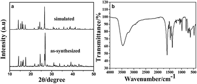 | ||
| Fig. 1 (a) XRD pattern of as-synthesized Mn-LMOF and the simulated pattern based on the crystal data of Mn-LMOF (b) FT-IR spectrum of the Mn-LMOF. | ||
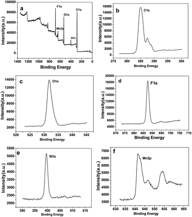 | ||
| Fig. 2 (a) XPS survey spectrum of the Mn-LMOF. (b–f) XPS core level spectra of C 1s, O 1s, F 1s, N 1s, and Mn 2p of the Mn-LMOF. | ||
Fig. S1† shows the TGA curve of the Mn-LMOF sample. Between 182 °C and 240 °C, the weight loss is due to the removal of two molecules of water (calcd 7.46%, found 7.02%), while the weight loss from 249 °C to 349 °C corresponds to the loss of the 4,4′-bpy molecule.
The morphology and microstructure of the as-synthesized Mn-LMOF after grinding for 2 h were examined by FESEM. As observed in Fig. 3a, the Mn-LMOF sample is built up of micro-sized particles; when seen from the higher magnification SEM image (Fig. 3b), these particles also consist of nanosheets and nanoparticles. Nanosheets and nanoparticles shorten the transmission distance of electrons/ions, which helps to increase the capacitance of the Mn-LMOF electrode.
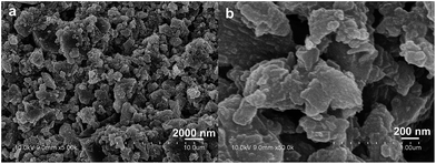 | ||
| Fig. 3 (a) Low-magnification and (b) high-magnification SEM images of as-synthesized Mn-LMOF after grinding for 2 h. | ||
Mn-LMOF is a two-dimensional (2D) layered coordination polymer with cavities, as shown in Fig. 4a. The 2D layers are formed by Mn(II) ions bridging with tetrafluoroterephthalate anions and 4,4′-bpy molecules. These 2D layers are further linked by the interaction of hydrogen bonding, resulting in the formation of a three-dimensional (3D) supramolecular framework, as displayed in Fig. S2.† The presence of hydrogen bonds increases the stability of the framework's 3D structure. Such interspace must be convenient for electrolyte diffusion and storage. The surface area, pore size distribution, and pore volume of the Mn-LMOF after grinding for 2 h were analyzed by nitrogen adsorption–desorption techniques. The single point adsorption total pore volume of pores and the BET surface area are 0.0167 cm3 g−1 and 17.08 m2 g−1, respectively. The N2 isotherm of the Mn-LMOF belongs to hybrid type III and IV, as presented in Fig. 4b. The hysteresis belongs to type H1. The pore size distribution can be obtained by the Barrett–Joyner–Halenda (BJH) method, which is displayed in the inset of Fig. 4b. The pore distribution with micropores, mesopores and macropores is observed. The maximum pore distribution appears at around 1.8 nm. The micropores should be ascribed to the cavities of the layered Mn-LMOF itself, while macropores and mesopores should originate from interparticle pores. Usually, high micro/mesoporosity is associated with high capacitance value,38,59 and hence the Mn-LMOF might act as a potentially high performance electrode material for supercapacitors.
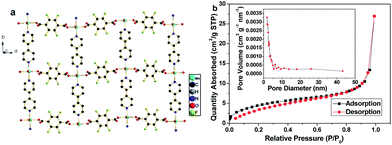 | ||
| Fig. 4 (a) 2D view of Mn-LMOF. (b) N2 adsorption–desorption isotherm of as-synthesized Mn-LMOF after grinding for 2 h, and the inset represents the pore size distribution curve. | ||
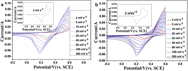 | ||
| Fig. 5 CV curves of the Mn-LMOF electrode at sweep rates from 2 to 200 mV s−1 in (a) 1 M KOH and (b) 1 M LiOH solution. | ||
Electrochemical properties
The electrochemical performances of the Mn-LMOF as an electrode material of supercapacitors were evaluated by cyclic voltammetry (CV) and galvanostatic charge–discharge in a three electrode system. The CV curve of the Mn-LMOF electrode at the scan rate of 2 mV s−1 in 1 M KOH solution is displayed in the inset of Fig. 5a. As can be clearly seen in the curve, a pair of redox peaks appears at around 0.3 and 0.46 V, which might be originating from the changing between manganese ions of different valence states, and indicates that the pseudo-capacitance mainly results from the surface redox reactions. Similar to the reported MOF-based electrode materials, such as {[Co(Hmt)(tfbdc)(H2O)2]·(H2O)2}n 38 and Ni3(btc)2·12H2O,45 this conversion process may be expressed by the following equations:| Mn(II)s + OH− ↔ Mn(II) (OH)ad + e− | (1) |
| Mn(II) (OH)ad ↔ Mn(III) (OH)ad + e− | (2) |
When the scan rate increases from 2 to 60 mV s−1, as shown in Fig. 5a, the peak separation between the oxidation and reduction peaks also increases. This increase should be relative to the increase of the internal resistance of the electrode.38 As the scan rate increases to 80–200 mV s−1, oxidation peaks disappear, indicating that the redox process of the electrode controlled by diffusion might be transferred to the control process of charge transfer or hybrid control process of diffusion and charge transfer.
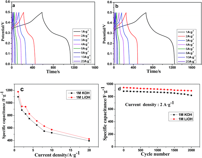
The charge–discharge profiles of the Mn-LMOF electrode were further studied in 1 M KOH solution within the potential window of 0 to 0.45 V at different current densities (Fig. 6a). Note, each discharge curve has a slope, which reveals that the electrode has a pseudocapacitive behavior originating from the redox reactions. According to the discharge profiles, the specific capacitances of the Mn-LMOF electrode (C, F g−1) are shown in Fig. 6c. The Mn-LMOF electrode has a high specific capacitance of 1098 F g−1 at a current density of 1 A g−1. Even at 20 A g−1, the specific capacitance can still be about 396 F g−1, showing an excellent rate capability. Compared with the MOF/coordination polymer based electrode materials reported recently and MnOx based electrode materials (Table S1†), the specific capacitance of 1098 F g−1 is also higher. As observed in Fig. 6c, the specific capacitance will decrease with the current density increasing, which should be attributed to the decrease in effective interaction between electrolyte ions and the electrode.38,60
To evaluate the cycle stability of the Mn-LMOF electrode, 2000 cycles of charge–discharge were measured at a current density of 2 A g−1. As presented in Fig. 6d, the Mn-LMOF can still retain 820 F g−1 (92.6% of the initial specific capacitance) after 2000 cycles. Fig. S3† displays the charge–discharge curves of the Mn-LMOF for the first three cycles at a current density of 3 A g−1. Each curve has similar time–potential response behaviour, further verifying the excellent electrochemical reversibility. After the testing of 1000 cycles, the FT-IR spectrum and XRD pattern of the Mn-LMOF electrode were measured (Fig. S4 and S5†). In comparison to the original Mn-LMOF electrode the band at 1632 cm−1 belonging to νas(OCO) still exists in the FT-IR spectrum after 1000 cycles, showing the conversion reversibility of tfbdc2− ions. Diffraction peak positions of the Mn-LMOF electrode after 1000 cycles are nearly the same as that of the bare electrode containing Mn-LMOF, polytetrafluoroethylene (PTFE) and acetylene black. These facts further reveal that the Mn-LMOF electrode has good cycling stability.
In the case of the supercapacitor using 1 M LiOH electrolyte, the CV curves and galvanostatic charge–discharge profiles, rate capability and cycle stability are similar to that of a supercapacitor using 1 M KOH (Fig. 5b, 6b–d and S6†); the specific capacitances are 1178, 945, 939, 826, 713, 630, 574 and 424 F g−1 at different current densities of 1, 2, 3, 4, 6, 8, 10 and 20 A g−1, respectively, slightly higher than those found when using 1 M KOH. After 2000 cycles, the specific capacitance remains at 94.6% of the initial capacitance.
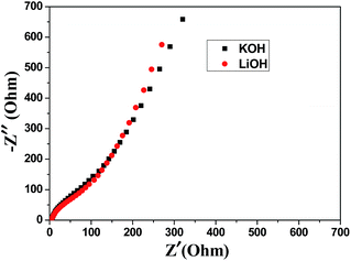
Electrochemical impedance spectroscopy (EIS) measurements were performed to further understand the electrochemical performances, and the results are presented in Fig. 7. In the high frequency range of the plot, the internal resistance (Rs) includes intrinsic resistance of the active material (Mn-LMOF), the ionic resistance of the electrolyte, and the contact resistance between the substrate and the active material.61 Rs values are 1.86 Ω for 1 M KOH and 1.96 Ω for 1 M LiOH. The values are comparable to that of the reported Co-LMOF electrode.38 The semicircle observed in the range of high frequency is related to charge transfer and surface resistance. Almost the same semicircles are observed in the plots of the 1 M KOH and 1 M LiOH electrolytes, indicating that the charge transfer resistances (Rct) are almost the same in the two electrolytes. The unapparent semicircle reveals a low Rct. At the low frequency region, the phase angle of the plot for the 1 M LiOH electrolyte is slightly larger than that for the 1 M KOH electrolyte, and the length of the Warburg line is shorter for the 1 M LiOH electrolyte, indicating that the diffusion impedance of the 1 M LiOH electrolyte is smaller, and the diffusion velocity of Li+ ion is faster.62 This result may be ascribed to the fact that the Li+ ion has a smaller radius.
The Mn-LMOF as a supercapacitor electrode material exhibits an excellent capacitive performance, which can be ascribed to the layered structure of Mn-LMOF, the Mn-LMOF nano-sized particles and the micro/mesoporosity of this material. First, the layered structure of Mn-LMOF can provide both metal ions involved in the faradaic reaction and enough interspaces for the storage and diffusion of the electrolyte. Second, the Mn-LMOF nano-sized particles can shorten the diffusion distance of the electrolyte and have more active sites for the faradaic reaction. In addition, the micro/mesoporosity is also beneficial for the transport of the electrolyte.
Conclusions
In summary, the Mn-LMOF electrode exhibits good cycling stability and high specific capacitance in two alkaline electrolytes. In the case of 1 M LiOH solution, a maximum specific capacitance of 1178 F g−1 is obtained at 1 A g−1, and the capacitance retention is 94.6% after 2000 cycles; the values are slightly higher (1098 F g−1, 92.6%) in the case of 1 M KOH solution. This is the first report of a layered Mn-based metal–organic framework being applied as a supercapacitor electrode material. Its excellent electrochemical performance and simple synthetic procedure indicate that the Mn-LMOF material with nanosheets and nanoparticle morphologies is a promising electrode material for supercapacitors. The results will encourage us to synthesize more MOFs based electrode materials with layered structures.Acknowledgements
We thank the National Natural Science Foundation of China (No. 20971060), the Project Funded by the Advanced Catalysis and Green Manufacturing Collaborative Innovation Center, the Natural Science Research Key Project of Jiangsu Colleges and Universities (No. 16KJA430005), and the Natural Science Foundation of the State Key Laboratory of Coordination Chemistry for the financial support.Notes and references
- M. Winter and R. J. Brodd, Chem. Rev., 2004, 104, 4245 CrossRef CAS PubMed.
- A. Burke, J. Power Sources, 2000, 91, 37 CrossRef CAS.
- R. Kötz and M. Carlen, Electrochim. Acta, 2000, 45, 2483 CrossRef.
- G. P. Wang, L. Zhang and J. J. Zhang, Chem. Soc. Rev., 2012, 41, 797 RSC.
- P. Soudan, J. Gaudet, D. Guay, D. Bélanger and R. Schulz, Chem. Mater., 2002, 14, 1210 CrossRef CAS.
- C. Z. Yuan, H. B. Wu, Y. Xie and X. W. Lou, Angew. Chem., Int. Ed., 2014, 53, 1488 CrossRef CAS PubMed.
- H.-W. Chang, Y.-R. Lu, J.-L. Chen, C.-L. Chen, J.-F. Lee, J.-M. Chen, Y.-C. Tsai, P.-H. Yeh, W.-C. Chou and C.-L. Dong, Phys. Chem. Chem. Phys., 2016, 18, 18705 RSC.
- W. F. Wei, X. W. Cui, W. X. Chen and D. G. Ivey, Chem. Soc. Rev., 2011, 40, 1697 RSC.
- J. Y. Wang, H. J. Tang, H. Ren, R. B. Yu, J. Qi, D. Mao, H. J. Zhao and D. Wang, Adv. Sci., 2014, 1, 1719 Search PubMed.
- F. Y. Yang, M. S. Zhao, Q. J. Sun and Y. Q. Qiao, RSC Adv., 2015, 5, 9843 RSC.
- R. T. Vinny, K. Chaitra, K. Venkatesh, N. Nagaraju and N. Kathyayini, J. Power Sources, 2016, 309, 212 CrossRef CAS.
- S. A. Ansari, N. Parveen, T. H. Han, M. O. Ansari and M. H. Cho, Phys. Chem. Chem. Phys., 2016, 18, 9053 RSC.
- G. H. Yu, L. B. Hu, N. Liu, H. L. Wang, M. Vosgueritchian, Y. Yang, Y. Cui and Z. N. Bao, Nano Lett., 2011, 11, 4438 CrossRef CAS PubMed.
- H. Furukawa, K. E. Cordova, M. O'Keeffe and O. M. Yaghi, Science, 2013, 341, 1230444 CrossRef PubMed.
- N. Stock and S. Biswas, Chem. Rev., 2012, 112, 933 CrossRef CAS PubMed.
- K. Ohara, M. Kawano, Y. Inokuma and M. Fujita, J. Am. Chem. Soc., 2010, 132, 30 CrossRef CAS PubMed.
- P. García-garcía, M. Müller and A. Corma, Chem. Sci., 2014, 5, 2979 RSC.
- A. Dhakshinamoorthy, A. M. Asiric and H. Garcia, Chem. Soc. Rev., 2015, 44, 1922 RSC.
- H. Deng, C. J. Doonan, H. Furukawa, R. B. Ferreira, J. Towne, C. B. Knobler, B. Wang and O. M. Yaghi, Science, 2010, 327, 846 CrossRef CAS PubMed.
- E. Tsivion, J. A. Mason, M. I. Gonzalez, J. R. Longacd and M. Headgordon, Chem. Sci., 2016, 7, 4503 RSC.
- Z. Zhong, L. R. Zhang, Y. Z. Li, Z. J. Guo and H. G. Zheng, J. Am. Chem. Soc., 2011, 133, 4172 CrossRef PubMed.
- O. S. Wenger, Chem. Rev., 2013, 113, 3686 CrossRef CAS PubMed.
- Y. F. Li, A. Y. Pang, C. J. Wang and M. Wei, J. Mater. Chem., 2011, 21, 17259 RSC.
- Q. Liu, L. L. Yu, Y. Wang, Y. Z. Ji, J. Horvat, M. L. Cheng, X. Y. Jia and G. X. Wang, Inorg. Chem., 2013, 52, 2817 CrossRef CAS PubMed.
- C. D. Shi, Q. H. Xia, X. Xue, Q. Liu and H. J. Liu, RSC Adv., 2016, 6, 4442 RSC.
- H. Y. Wang, Y. Wu, C. F. Leong, D. M. D'Alessandro and J. L. Zuo, Inorg. Chem., 2015, 54, 10766 CrossRef CAS PubMed.
- A. Morozan and F. Jaouen, Energy Environ. Sci., 2012, 5, 9269 CAS.
- F. S. Ke, Y. S. Wu and H. J. Deng, J. Solid State Chem., 2015, 223, 109 CrossRef CAS.
- L. Wang, Y. Han, X. Feng, J. Zhou, P. Qi and B. Wang, Coord. Chem. Rev., 2016, 307, 361 CrossRef CAS.
- S. L. Li and Q. Xu, Energy Environ. Sci., 2013, 6, 1656 CAS.
- H. Pang, F. Gao, Q. Chen, R. M. Liu and Q. Y. Lu, Dalton Trans., 2012, 41, 5862 RSC.
- B. Liu, H. Shioyama, T. Akita and Q. Xu, J. Am. Chem. Soc, 2008, 130, 5390 CrossRef CAS PubMed.
- R. Díaz, M. Gisela Orcajo, J. A. Botas, G. Calleja and J. Palma, Mater. Lett., 2012, 68, 126 CrossRef.
- D. Y. Lee, S. J. Yoon, N. K. Shrestha, S. H. Lee, H. Ahn and S. H. Han, Microporous Mesoporous Mater., 2012, 153, 163 CrossRef CAS.
- D. Y. Lee, D. V. Shinde, E. K. Kim, W. Lee, W. I. Oh, N. K. Shrestha, J. K. Lee and S. H. Han, Microporous Mesoporous Mater., 2013, 171, 53 CrossRef CAS.
- H. Yu, D. Xu and Q. Xu, Chem. Commun., 2015, 51, 13197 RSC.
- L. Wang, X. Feng, L. Ren, Q. Piao, J. Zhong, Y. Wang, H. Li, Y. Chen and B. Wang, J. Am. Chem. Soc., 2015, 137, 4920 CrossRef CAS PubMed.
- X. Liu, C. Shi, C. Zhai, M. Cheng, Q. Liu and G. Wang, ACS Appl. Mater. Interfaces, 2016, 8, 4585 CAS.
- J. Yang, Z. H. Ma, W. X. Gao and M. Wei, Chem.–Eur. J., 2016, 23, 631 CrossRef PubMed.
- K. M. Choi, H. M. Jeong, J. H. Park, B. Y. Zhang, J. K. Kang and O. M. Yaghi, ACS Nano, 2014, 8, 7451 CrossRef CAS PubMed.
- Y. Tan, W. Zhang, Y. Gao, J. Wu and B. Tang, RSC Adv., 2015, 5, 17601 RSC.
- D. Zhang, H. Shi, R. Zhang, Z. Zhang, N. Wang, J. Li, B. Yuan, H. Bai and J. Zhang, RSC Adv., 2015, 5, 58772 RSC.
- J. Yang, P. Xiong, C. Zheng, H. Qiu and M. Wei, J. Mater. Chem. A, 2104, 2, 16640 RSC.
- J. Yang, C. Zheng, P. Xiong, Y. Li and M. Wei, J. Mater. Chem. A, 2014, 2, 19005 CAS.
- L. Kang, S. X. Sun, L. B. Kong, J. W. Lang and Y. C. Luo, Chin. Chem. Lett., 2014, 25, 957 CrossRef CAS.
- C. Qu, Y. Jiao, B. Zhao, D. Chen, R. Zou, K. S. Walton and M. Liu, Nano Energy, 2016, 26, 66 CrossRef CAS.
- P. Wen, P. Gong, J. Sun, J. Wang and S. Yang, J. Mater. Chem. A, 2015, 3, 13874 CAS.
- Y. Yan, P. Gu, S. S. Zheng, M. B. Zheng, H. Pang and H. G. Xue, J. Mater. Chem. A, 2016, 4, 19078 CAS.
- Y. Jiao, J. Pei, D. H. Chen, C. S. Yan, Y. Y. Hu, Q. Zhang and G. Chen, J. Mater. Chem. A, 2017, 5, 1094 CAS.
- D. Sheberla, J. C. Bachman, J. S. Elias, C. J. Sun, Y. Shao-Horn and M. Dinca, Nat. Mater., 2017, 16, 220 CrossRef CAS PubMed.
- Y. J. Zhou, Z. M. Mao, W. Wang, Z. K. Yang and X. Liu, ACS Appl. Mater. Interfaces, 2016, 8, 28904 CAS.
- Y. Gong, J. Li, P. G. Jiang, Q. F. Li and J. H. Lin, Dalton Trans., 2013, 42, 1603 RSC.
- M. Du, M. Chen, X. G. Yang, J. Wen, X. Wang, S. M. Fang and C. S. Liu, J. Mater. Chem. A, 2014, 2, 9828 CAS.
- Q. Liu, X. Liu, C. Shi, Y. Zhang, X. Feng, M. L. Cheng, S. Su and J. Gu, Dalton Trans., 2015, 44, 19175 RSC.
- A. Ehsani, J. Khodayari, M. Hadi, H. Mohammad Shiri and H. Mostaanzadeh, Ionics, 2017, 23, 131 CrossRef CAS.
- Y. Zhang, B. Lin, Y. Sun, X. Zhang, H. Yang and J. Wang, RSC Adv., 2015, 5, 58100 RSC.
- N. Campagnol, R. Romero-Vara, W. Deleu, L. Stappers, K. Binnemans, D. E. Devos and J. Fransaer, ChemElectroChem, 2014, 1, 1182 CrossRef CAS.
- S. Liu, D. Wang and S. Pan, Analysis of X-ray Photoelectron Spectroscopy, Science Press, Beijing, 1998 Search PubMed.
- K. Deori, S. K. Ujjain, R. K. Sharma and S. Deka, ACS Appl. Mater. Interfaces, 2013, 5, 10665 CAS.
- T. Yan, Z. J. Li, R. Y. Li, Q. Ning, H. Kong, Y. L. Niu and J. K. Liu, J. Mater. Chem., 2012, 22, 23587 RSC.
- B. E. Conway, Electrochemical Supercapacitors: Scientific Fundamentals and Technological Applications, Springer Science & Business Media, 2013 Search PubMed.
- R. B. Rakhi, B. Ahmed, D. Anjum and H. N. Alshareef, ACS Appl. Mater. Interfaces, 2016, 8, 18806 CAS.
Footnote |
| † Electronic supplementary information (ESI) available: TGA curve and 3D view of Mn-LMOF, as well as the IR spectra, XRD patterns and the additional electrochemical data of Mn-LMOF electrode. See DOI: 10.1039/c7ra04374k |
| This journal is © The Royal Society of Chemistry 2017 |


