 Open Access Article
Creative Commons Attribution 3.0 Unported Licence
Swollen liquid crystals (SLCs): a versatile template for the synthesis of nano structured materials
Sunil Dutt
 *a,
Prem Felix Siril
b and
Samy Remita
 cd
cd
aInstitute of Materials Science and Nanotechnology (UNAM), National Nanotechnology Research Center, Bilkent University, Ankara 06800, Turkey. E-mail: sunildutt.iitmandi@gmail.com
bSchool of Basic Sciences, Indian Institute of Technology Mandi, Mandi-175001, Himachal Pradesh, India
cLaboratoire de Chimie Physique, UMR8000, CNRS, Université Paris-Sud 11, Bât. 349, Campus d'Orsay, 15 Avenue Jean Perrin, 91405 Orsay Cedex, France
dDépartement CASER, Ecole SITI, Conservatoire National des Arts et Métiers, CNAM, 292 rue Saint-Martin, 75141 Paris Cedex 03, France
First published on 17th January 2017
Abstract
Liquid crystal (LCs) is the state of matter that exhibits properties between a conventional liquid and solid crystals. Liquid crystals mainly can be classified into two types: thermotropic and lyotropic liquid crystals. A thermotropic liquid crystal shows properties that are dependent on temperature conditions. On the other hand in lyotropic liquid crystals (LLCs), the amphiphiles are dissolved in a solvent and exhibit liquid crystalline properties in certain concentration ranges. In the literature, lot of reviews have been presented on thermotropic and lyotropic liquid crystals (LLCs). But nowadays, swollen liquid crystals (SLCs) have become a much more important area of research because of their easily tunable properties, their stability and versatility of the system. Swollen liquid crystals (SLCs) consist of infinite liquid crystalline non polar cylinders organized on a hexagonal lattice in a polar medium and are prepared with the proper ratios of salted water and non polar solvents with cationic or anionic or non ionic surfactants and co surfactants i.e. water![[thin space (1/6-em)]](https://www.rsc.org/images/entities/char_2009.gif) :
:![[thin space (1/6-em)]](https://www.rsc.org/images/entities/char_2009.gif) oil
oil![[thin space (1/6-em)]](https://www.rsc.org/images/entities/char_2009.gif) :
:![[thin space (1/6-em)]](https://www.rsc.org/images/entities/char_2009.gif) surfactant
surfactant![[thin space (1/6-em)]](https://www.rsc.org/images/entities/char_2009.gif) :
:![[thin space (1/6-em)]](https://www.rsc.org/images/entities/char_2009.gif) cosurfactant. In this review article, we will briefly discuss the synthesis of swollen liquid crystals (SLCs), factors affecting their stability, different kinds of nanomaterials such as metallic, bimetallic, polymeric nanostructures synthesized inside swollen liquid crystals (SLCs) using different methods and the effect of swollen liquid crystal (SLC) confinement on the final morphology of nanomaterials with their potential applications.
cosurfactant. In this review article, we will briefly discuss the synthesis of swollen liquid crystals (SLCs), factors affecting their stability, different kinds of nanomaterials such as metallic, bimetallic, polymeric nanostructures synthesized inside swollen liquid crystals (SLCs) using different methods and the effect of swollen liquid crystal (SLC) confinement on the final morphology of nanomaterials with their potential applications.
1. Introduction
The tremendous progress in the field of nano science and nano technology in recent years leads to the development of new materials at the nano scale with improved properties for different applications. But, a major research task is to control the size and shape of bulk materials at the nano level. So different methods were reported in the literature for the synthesis of materials at the nano scale such as membranes,1 electrospinning,2,3 template assisted,4,5 sol–gel,6,7 microemulsions,8 hydrothermal, sonochemical, microwave methods9 etc. There are advantages and disadvantages of these methods. For example, among the template assisted synthetic routes, soft templates are easier and more convenient to use than the hard templates. This is because post synthesis removal of hard templates such as mesoporous silica, anodized aluminium oxide etc. usually require harsh conditions, which may even rupture the prepared nanostructures.10 On the other hand soft templates, such as micelles that are formed by the self-assembly of surfactants and polymers can be easily removed by simple washing after the synthesis of nanostructures.11Swollen liquid crystals (SLCs) have attracted much more attention in the recent years due to their potential applications in many technological important research areas. This surfactant mesophases act as very useful and versatile templates for the synthesis of nanostructured materials. Swollen liquid crystals (SLCs) are formed by a quaternary mixture of surfactant, co-surfactant, water and oil.
Nanostructures can be synthesized using both aqueous phase and organic phase of swollen liquid crystals (SLCs). Depending upon the composition, cubic, hexagonal and lamellar phases may be formed in such a quaternary mixture.12 These mesophases can be used as structure directing templates as they are stable over a wide range of pH, temperature and composition.13 They are called ‘swollen’ liquid crystals because the aspects of the assembly can be varied by changing the composition. For example, diameter of the tubular assembly of surfactants in hexagonal mesophases can be varied over a decade from ∼3 nm to ∼30 nm by changing the composition of the quaternary mixture. Even the distance between the tubes can be varied independently.14 Swollen liquid crystals (SLCs) can be formed from cationic, anionic and nonionic surfactants. They were used as soft templates in the synthesis of different nanostructures. In this review article, we will discuss briefly about the surfactants self-assembly, liquid crystals, swollen liquid crystals (SLCs) and their stability, different nanostructure synthesis using swollen liquid crystals (SLCs) etc. in much more detail.
2. Surfactants and their self-assembly
Surfactant self-assembly takes the advantage for synthesis of different nanostructured materials without nanostructures damage. Thus, the surfactants can self-assemble to form micelles above critical micelle concentration (CMC) and these micelles can be used as soft templates for nanomaterials synthesis. Thus, this approach for nanomaterials synthesis attracted much more attention in scientific community. Hence, it leads to the synthesis of different type of nanomaterials and more importantly, the nanomaterials size and shape can be tuned up using different concentration of surfactants.15 So, its important area of research work but before going to further detailed discussion, we need to discuss about critical packing parameter (CPP), Fontell scheme, phase diagram.Critical packing parameter (CPP)
The critical packing parameter (CPP) is the most important parameter to determine the self-assembly behavior of amphiphilic molecules in micelles and was proposed by Israelachvili and co-workers.16,17Estimating of this critical packing parameter (CPP) enables the determination of the surfactants molecular packing and formed preferred structure such as micelles, cylindrical micelles, bilayers, inverted micelles etc. as shown in Fig. 1 as determined by their respective critical packing parameter (CPP).
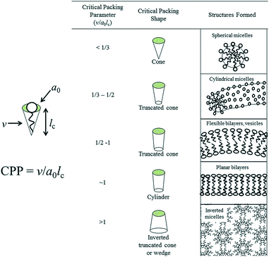 | ||
| Fig. 1 Molecular shapes and critical packing parameter (CPP) of surfactants and lipids and the structures formed (here, v = volume of hydrocarbon core, ao = effective head group area, lc = hydrocarbon chain length). Adapted with permission from ref. 18, copyright 2014, Royal Society of Chemistry. | ||
Fontell scheme for surfactant self-assembly of surfactants is also shown in Fig. 2, which clearly represents the normal and reverse mesophases formation.
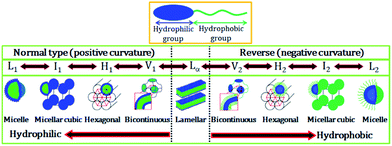 | ||
| Fig. 2 Schematic representation of an amphiphilic molecule and normal and reverse type of surfactant self-assembled structures. L1, I1, H1, V1, and Lα represents normal micelle, micellar cubic phase, hexagonal phase, bicontinuous cubic phase, and lamellar phase, respectively. V2, I2, H2, and L2α respectively represent reverse (inverted) phases. Adapted with permission from ref. 19, copyright 2014, Multidisciplinary Digital Publishing Institute. | ||
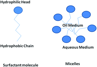
Surface active agents, commonly known as surfactants, are the organic molecules that have hydrophilic polar head groups and long hydrophobic tail group(s). They have the tendency to get adsorbed at the interface between aqueous and oil medium. This results in the lowering of the free energy of phase boundary. Thus, they can reduce surface or interfacial tension. Surfactants exist as unimers below the critical micelle concentration (CMC) in water. However, they can self-assemble to form micelles above the critical micelle concentration (CMC).18,20 In water, the hydrophobic tail groups of surfactant molecules are directed toward the interior of the core and the hydrophilic head groups are oriented toward the aqueous medium. Micelles can be treated as oil droplets in water and hence can solubilize oils inside the core to form oil-in-water emulsions, as shown in Fig. 3. Usually, micelles can be of spherical and cylindrical shapes depending on the shape of the surfactant molecules. However, micelles can be of less common shapes such as prolates, oblates, etc. At certain conditions, micelles can further self-assemble to form different types of mesophases such as hexagonal, cubic, lamellar and reverse hexagonal as shown in the phase diagram (Fig. 4). The micelles and the mesophases can be used as versatile templates for preparing different nanostructures such as of mesoporous and core–shell silica, nanofibers and rod-shaped mesoporous silica, TiO2 hollow structures etc.21–23
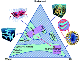 | ||
| Fig. 4 A three component (water, oil and surfactant) phase diagram showing the formation of micelles and mesophases by the self-assembly of surfactants. Adapted with permission from ref. 24, copyright 2015, Royal Society of Chemistry. | ||
3. Liquid crystals (LCs)
Liquid crystals have gained much attention in the recent years due to their wide applications in different areas. Liquid crystals (LCs) is the state of matter that have the properties of both the liquid (molecular mobility and fluidity) and the crystalline (optical and electrical anisotropy) states.25 Liquid crystals (LCs) can also be defined as the mesophase that exhibits the properties of liquid i.e. they can flow like liquid and possess the long range orientational order.26 Liquid crystals (LCs) are mainly classified into two types: thermotropic liquid crystals and lyotropic liquid crystals (LLCs).3.1. Classifications of liquid crystals
3.1.1.1. Nematic phases. Nematic phase is the mostly fluid and widely used phase. Nematic phase has long range molecular positional ordering i.e. long axis of the molecule and tends to align in preferential direction, but has no positional ordering.27
3.1.1.2. Smectic phases. These types of mesophases are formed at lower temperature than nematic phases. The molecules are arranged in layers and exhibit some correlations in their positions in addition to the orientational ordering.
Extensive research was carried out on lyotropic liquid crystals (LLCs) and received much attention recently. Lyotropic liquid crystals (LLCs) can be used for the synthesis of Bi, PdS nanoparticles.32 In lyotropic liquid crystals (LLCs) the main physical variation is concentration that determines the mesophase formation, whereas in thermotropic liquid crystals the main physical variation is temperature.33 Moreover, in lyotropic liquid crystals (LLCs), the main parameter is the concentration, which determine the phase transition also.34 Moreover, in thermotropic liquid crystals, it is already reported in the literature that the “blue phases” of liquid crystals exists both in narrow range and wide range of temperature.35 Also, the refractive index of the thermotropic liquid crystals were determined by temperature.36 Four-stranded aggregates of oligodeoxyguanylates and intermolecular hydrogen bonding interactions plays also role in formation of lyotropic liquid crystals and thermo liquid crystals respectively.37,38
Hexagonal, lamellar and cubic mesophases in lyotropic liquid crystals (LLCs) can be used as template for controlling the structure and morphology of the desired nanomaterial. In hexagonal mesophases, the long cylindrical micelles are arranged in hexagonal pattern. Each surfactant cylinder is surrounded by six other surfactant cylinders.14
In lamellar mesophases, the surfactant molecules were arranged in bilayer fashion. The thickness of the bilayer is less than twice the surfactant molecular length. Lamellar mesophases can be used to synthesize different nanostructures. If the role of polar and nonpolar groups in surfactant chain has changed then it's called as reverse micelles and reverse hexagonal mesophase. Very recently, Toshihiko Oka and Noboru Ohta developed a method for the synthesis of two distinct domains of lyotropic liquid crystals (LLCs) with straight and ring cylinders in capillaries as shown in Fig. 5 and 6.39
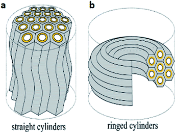 | ||
| Fig. 5 (a) Straight cylinders with undulation and (b) ringed cylinders arrangements of hexagonal cylinders. Reprinted with permission from ref. 39. Copyright 2016 American Chemical Society. | ||
 | ||
| Fig. 6 Glyceryl monooleyl ether (GME) sample in a 0.2 mm diameter quartz capillary under polarized light. (a) Without an analyzer (a polarizer only) (b) and (c) Glyceryl monooleyl ether (GME) sample under polarized light when polarizer and analyzer are perpendicular to each other. Reprinted with permission from ref. 39. Copyright 2016 American Chemical Society. | ||
Reversible photorheological lyotropic liquid crystals (LLCs) were recently reported by S. Peng et al.31 In their research, they showed that lyotropic liquid crystals (LLCs) based on azobenzene-containing surfactant (azo-surfactant) showed reversible photorheological behavior under UV and visible light as shown in Fig. 7. UV irradiation induced the trans to cis isomerization of the azo-surfactant, leading to the disruption of the ordered lyotropic liquid crystals (LLCs) phases and a dramatic rapid decrease in the viscosity and modulus.
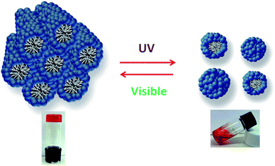 | ||
| Fig. 7 Reversible behavior of photorheological lyotropic liquid crystals under UV and visible light. Reprinted with permission from ref. 31. Copyright 2014 American Chemical Society. | ||
3.2. Applications of lyotropic liquid crystals (LLCs) in nanomaterials synthesis
Lyotropic liquid crystals (LLCs) directed synthesis of nanomaterials are well known and widely reported in literature. Lyotropic liquid crystals (LLCs) (lamellar, hexagonal, cubic phases) can be used in the synthesis of zero dimensional, one dimensional, two dimensional, three dimensional nanomaterials. The lyotropic liquid crystals (LLCs) can also be used as template to synthesize nano sheets, nano particles, nano rods, porous nanostructures etc. Control over the geometry and interconnectivity of lyotropic liquid crystals (LLCs) nano channels allow us to control the size and shape of the nanostructures.40Lamellar mesophase can be used as soft template confinement to synthesize gold nanoparticles and nanorods by the radiolytic reduction of metal salt.41 Nanoparticles of different diameter can be synthesized by tuning the thickness of water layer in the mesophase. In micellar solution above critical micelle concentration (CMC) gold nanorods of different aspect ratio can be synthesized by radiolysis.42
The lyotropic liquid crystals (LLCs) can be used to synthesize zero dimensional, one dimensional and three dimensional nanostructures. We discuss the synthesis of these different nanostructures as below:
The lyotropic liquid crystals (LLCs) nano reactor approach can be used in nanoparticles synthesis. The reactants were confined in these lyotropic liquid crystals (LLCs) nano channels for nanostructures synthesis.32 In typical synthesis, BiCl3 and CrCl2 (a powerful reducing agent) as precursors salts were trapped inside the lyotropic liquid crystals (LLCs) separately in disposable syringes. After that, these two liquid crystals are connected and shear mixed, which leads to the synthesis of bismuth nanoparticles as shown in Fig. 8.32
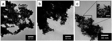 | ||
| Fig. 8 TEM images of Bi nanoparticles produced by shear mixing of lyotropic liquid crystals (LLCs) (a) hexagonal phase (b) lamellar phase (c) inverse hexagonal phase. Reprinted with permission from ref. 32. Copyright 2004 American Chemical Society. | ||
1-D nano structures are also nowadays an important area of research and lyotropic liquid crystals (LLCs) can be used to synthesize 1-D nano materials such as nanowires, nanorods and nanotubes etc. The AgBr and SnO2 micro wires were synthesized by mixing cetyltrimethyl ammonium bromide (CTAB) with oligoethylene alkyl ether/water semetic liquid crystals containing AgNO3 or SnF2.43 Crystalline silver nanowire arrays with a high aspect ratio by electrodeposition from a reverse hexagonal liquid-crystalline phase containing one-dimensional aqueous channels were also synthesized by substituting the water phase with 0.1 M AgNO3 solution.44
2-D nano structured materials are also very much interesting both for academic as well as industrial research. The lyotropic liquid crystals (LLCs) template synthesis approach can be extended to synthesize 2-D nano structured materials. Hideya et al., reported the synthesis of Pt nano sheets based on new methodology using chemical reduction of platinum salt (H2PtCl6) reducing with hydrazine in lyotropic liquid crystals (LLCs). The HR-TEM images of Pt-nano sheets synthesized using lyotropic liquid crystals (LLCs) were shown in Fig. 9.45
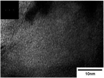 | ||
| Fig. 9 HR-TEM image of Pt-nano sheets synthesized in lyotropic liquid crystals (LLCs). Reprinted with permission from ref. 45. Copyright 2005 American Chemical Society. | ||
Ordered mesoporous silicates (MCM-41) and the mesoporous molecular sieves can also be synthesized after the removal of organic template by calcination.46
4. Swollen liquid crystals (SLCs)
Swollen liquid crystals (SLCs) are the class of lyotropic liquid crystals (LLCs) that are usually formed by a quaternary mixture of aqueous phase (brine or metallic salts etc.), oil (cyclohexane or aniline etc.), surfactant (cetyl trimethylammonium bromide (CTAB) or sodium dodecyl sulphate (SDS) etc.) and cosurfactant (1-pentanol). The interesting aspect of swollen liquid crystals (SLCs) is the tunability of various aspects of the mesophase assembly. For example, the diameter of the infinitely long surfactant cylinders in hexagonal mesophases can be varied from ∼3 to 30 nm by varying the oil to water ratio (swelling the oil phase) and the concentration of salts in the aqueous solution as shown in Fig. 10.47 Interestingly, even the distance between the surfactant cylinders can also be independently varied (swelling the aqueous phase).47 Thus, the name ‘swollen’ liquid crystals is due to the possibility to swell the aqueous and oil phases.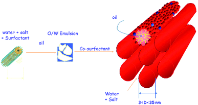 | ||
| Fig. 10 Formation of swollen hexagonal mesophase from a four component system: water, surfactant, oil and cosurfactant. | ||
Swollen liquid crystals (SLCs) are highly versatile as they can be formed by cationic, anionic and nonionic surfactants. Additionally, NaCl can be replaced with a large number of metal salts. Even, any water immiscible organic solvent can be used as oil phase. As the swollen liquid crystals (SLCs) can incorporate a large variety of organic and inorganic material inside and due to their tolerance to variation in pH and temperature within certain ranges, they can be used as ‘nanoreactors’.48,49 Swollen liquid crystals (SLCs) can be of hexagonal, lamellar and cubic mesophases and hence they can be used as versatile templates for controlling the structure and morphology of variety of nanomaterials such as metals, polymers, metal oxides, etc.48 In hexagonal mesophases, the long cylindrical micelles are arranged in a hexagonal lattice. Each surfactant cylinder is surrounded by six other surfactant cylinders as shown in Fig. 10. The order of viscosity of the swollen liquid crystals (SLCs) varies in the following order: cubic > hexagonal > lamellar. It has also been demonstrated that the diameter of the non-polar cylinders in swollen liquid crystals (SLCs) can be correlated by following equation:50
When the ionic forces increase, accessible radii of cylinders, R, go from 1.5 nm (with pure water and without oil) to 17 nm (with brine 0.5 M), while the distance between adjacent tubes is kept small and nearly constant (between 2.1 and 2.9 nm).50 Thus the diameter as well as the distance between the non-polar tubes in swollen liquid crystals (SLCs) can be controlled by the adjustment between cyclohexane and the ionic force of the aqueous salt solution.
4.1. Characterization of swollen liquid crystals (SLCs)
Swollen liquid crystals (SLCs) can be characterized using different characterization techniques such as small angle X-ray scattering (SAXS), polarizing optical microscopy (POM) and cryo-transmission electron microscopy (cryo-TEM).![[thin space (1/6-em)]](https://www.rsc.org/images/entities/char_2009.gif) :
:![[thin space (1/6-em)]](https://www.rsc.org/images/entities/char_2009.gif) (3)1/2
(3)1/2![[thin space (1/6-em)]](https://www.rsc.org/images/entities/char_2009.gif) :
:![[thin space (1/6-em)]](https://www.rsc.org/images/entities/char_2009.gif) 2, which corresponds to the (10), (11) and (20) diffraction planes. The first peak position, q0, allows a direct determination of the hexagonal lattice parameter, a, according to a = (2/31/2)(2π/q0).51 The hexagonal lattice parameter (a) is the distance between the centers of two adjacent surfactant cylinders in the swollen liquid crystals (SLCs).
2, which corresponds to the (10), (11) and (20) diffraction planes. The first peak position, q0, allows a direct determination of the hexagonal lattice parameter, a, according to a = (2/31/2)(2π/q0).51 The hexagonal lattice parameter (a) is the distance between the centers of two adjacent surfactant cylinders in the swollen liquid crystals (SLCs).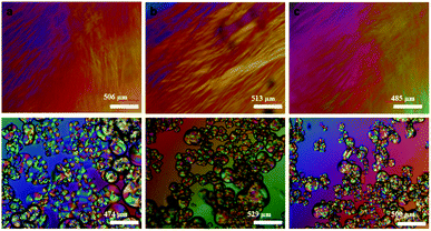 | ||
| Fig. 11 Room temperature crossed polarizing optical microscopy (POM) optical images of (a–c) fresh mesophases containing aniline, aniline hydrochloride and H2PtCl6·6H2O respectively, (d–f) fan shaped focal conic texture in the same samples after 48 hours. Reproduced from ref. 52 with permission from Elsevier. | ||
Moreover, metal nano clusters can be trapped inside the surfactants tubes of swollen liquid crystals (SLCs). The clusters can be heated to 55 °C and cooled to 20 °C and it's observed that it showed the breakage and deformation of crystalline structure in polarizing optical microscopy (POM).53
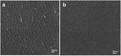 | ||
| Fig. 12 Cryo-transmission electron microscopy (TEM) clearly shows the presence of an array of tubular rod-like micelles in the hexagonal swollen liquid crystals (SLCs) (a and b). Reproduced from ref. 54 with permission from the Centre National de la Recherche Scientifique (CNRS) and The Royal Society of Chemistry. | ||
4.2. Stability of swollen liquid crystals (SLCs) against change in chemical nature of the salts, inclusion of chemicals and materials, pH of the medium and temperature
A number of studies on the inclusion of various chemicals and materials in the aqueous and oil phases of swollen liquid crystals (SLCs) have been reported.48,55,56 Very often these inclusions have been termed as ‘doping’ of the mesophases. The stability of swollen liquid crystals (SLCs) was not affected by the change of metal salts such as NaF, KCl and Na2SO4 in place of NaCl.51 Even, the range of stability of swollen liquid crystals (SLCs) for brine was established in the concentration range of 01.1 to 0.5 M.57 Stable swollen liquid crystals (SLCs) were prepared by varying the pH from 1 to 11.51 The oil phase of hexagonal swollen liquid crystals (SLCs) was doped with 1,4-diphenylbutadiyne (DPB) which is a monomer and polymerization could be achieved within oil phases using benzoin methyl ether (BME) as a catalyst.51 Addition of amphiphilic copolymers such as amphiphilic polymer consisting of a polyethylene oxide (PEO) central block of molecular weight 5000 g mol−1 grafted at one extremity to a C18H37 aliphatic chain decorate at oil/water interface can increase the stability of surfactant hexagonal mesophases.47Although, if the swelling ratio of oil/water(O/W) phase was varied even then the surfactants tubes remains in hexagonal pattern, swollen liquid crystals (SLCs) doped with 0.1 M Pd/Pt salts with different O/W ratio 1.5 to 4.5.55
This hexagonal assembly has also been used for the synthesis of porous Pt nanostructures using γ-irradiation.58 Before and after γ-irradiation the hexagonal structure is preserved as shown below in Fig. 13, showing the stability of mesophase.
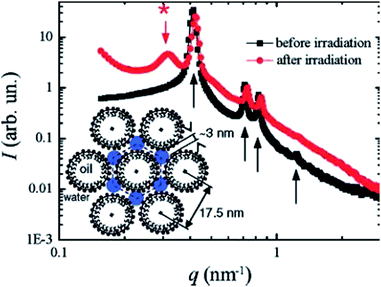 | ||
| Fig. 13 Small angle X-ray scattering (SAXS) pattern of a Pt-doped swollen liquid crystals (SLCs), before (black squares) and after (red circles) γ-irradiation. Before irradiation the diffraction pattern is characteristic of a hexagonal phase and even after irradiation, the hexagonal structure is preserved. Reprinted with permission from ref. 58. Copyright 2007 American Chemical Society. | ||
Moreover, even in bimetallic synthesis of metal nanostructures, the doping of the mesophases with metal salts as precursors does not affect the stability of hexagonal arrangement of surfactant tubes as shown in Fig. 14. Small angle X-ray scattering (SAXS) experiments showed hexagonal symmetry in swollen liquid crystals (SLCs), with three Bragg peaks whose position are in the ratio 1![[thin space (1/6-em)]](https://www.rsc.org/images/entities/char_2009.gif) :
:![[thin space (1/6-em)]](https://www.rsc.org/images/entities/char_2009.gif) 31/2
31/2![[thin space (1/6-em)]](https://www.rsc.org/images/entities/char_2009.gif) :
:![[thin space (1/6-em)]](https://www.rsc.org/images/entities/char_2009.gif) 2. The measured lattice parameter d is 24.5 nm.59
2. The measured lattice parameter d is 24.5 nm.59
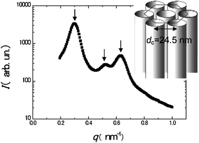 | ||
| Fig. 14 Small angle X-ray scattering (SAXS) spectrum of the Pd–Au doped hexagonal mesophase and scheme of the structure of the mesophase. The arrows point to the three main peaks. Reprinted with permission from ref. 59. Copyright 2009 American Chemical Society. | ||
P. Fabre et al. explored the possibility of incorporating solid particles into lyotropic liquid crystals (LLCs) and concluded that it is possible to dope a lamellar mesophase with tiny solid particles without disturbing the initial smectic structure.60 C. Quilliet et al. studied the doping of the mesophase with nanoparticles suspended in cylcohexane.61,62 The presence of such particles affected the lamellar structure and the lamellar zone shifted towards lower cosurfactant concentration with increase in particles.61,62 Interestingly, inclusion of ferrofluids in swollen liquid crystals (SLCs) by replacing the oil phase with ferrofluids was also studied and these swollen liquid crystals (SLCs) showed strong magnetic anisotropy under a magnetic field.63,64 The behavior of the doped mesophase under magnetic field was studied using polarizing optical microscopy. It is also possible to trap magnetic particles up to a volume fraction of 2% inside the non-polar medium of the surfactant cylinders. The cylinder should be larger enough and the diameter of cylinder should be twice the diameter of trapped particle.57
Nanoparticles of Pd, Ru, Ag, Au and Cu can be trapped inside the hexagonal mesophases.53 Cold welding of these trapped metal nanoparticles was explored as a method to prepare nanostructures, as the swollen liquid crystals (SLCs) can be heated up to 55 °C and can be cooled down to 20 °C to break and reform their crystalline behavior.53 The rheological behavior of oil swollen hexagonal liquid crystals was also investigated with small angle X-ray scattering (SAXS). The cylinders were found to be preferentially oriented along the flow and the hexagonal phase exhibits a polycrystalline texture at low shear regime. However, high shear has the effect of melting the long-range two-dimensional (2D) order of the cylinders, leading to a 2D liquid of cylinders strongly aligned along the flow.64
A very important parameter, the co-surfactant determines the stability and phase transition of hexagonal pattern of swollen liquid crystals (SLCs).65 The stability and phase transition of different phases of swollen liquid crystals (SLCs) was determined using 1-pentanol as co-surfactant. The influence of 1-pentanol on the stability of swollen liquid crystals (SLCs) can be visualized directly and also using polarizing optical microscopy (POM) and small angle X-ray scattering (SAXS).65
5. Use of swollen liquid crystals (SLCs) as soft templates
Nanomaterials are interesting because of the novel properties that arise due to their nanometric size. These novel optical, electrical, electronic, mechanical and thermal properties can be tuned by varying the size as well as shape of nanomaterials. Hence, controlling the morphology of nanomaterials in the nanoscale is very important. Among the plethora of methods that are available for controlling the morphologies of nanomaterials, template assisted synthesis is more straightforward. This is mainly because of the possibility of rational design and synthesis of nanostructures by replicating the nanostructured molds (templates). Porous solids such as mesoporous silica, anodized aluminum oxide (AAO) and etched polycarbonate membranes that have ordered porosity can be used as templates.66 These are called ‘hard’ templates. On the other hand micelles and lyotropic liquid crystals (LLCs) also have ordered pores in the nanometer length scales and they can also be used as ‘soft’ templates.67 Both hard and soft templates are widely used for preparing various nanostructures.66,68 Soft templates are easy and convenient to use than the hard templates in certain aspects, especially when the pure nanomaterial has to be retrieved from the template. Removal of hard templates usually requires harsh conditions such as the use of highly corrosive chemicals, that may even rupture the prepared nanostructures.69 On the other hand soft templates can easily be removed by simple washing after the synthesis of nanostructures.70 In the template assisted synthesis of nanomaterials, a precursor is first entrapped in the template. Subsequently, chemical reactions are initiated and the particle growth occurs while it is confined within the nano-chambers of the templates, thus leading to the formation of a replica. In hexagonal swollen liquid crystals (SLCs), the reaction can be performed in aqueous continuous medium which exists as a triangular space between three adjacent surfactant cylinders or in the oil medium within the surfactant cylinders.Hexagonal mesophases were used widely to synthesize different noble metal nanostructures.55,71 Very high concentrations (up to 0.5 M) of metal salts can be entrapped in the swollen liquid crystals (SLCs) by using them as the ionic medium in the aqueous phase for the formation of swollen liquid crystals (SLCs). On the other hand, oil soluble metal salts can be dissolved in the oil phase also.70 The metal salts entrapped in the swollen liquid crystals (SLCs) can then be reduced to prepare the metal nanostructures. The reduction can be performed by exposing to reducing vapours and gases such as hydrazine, CO and H2.70 Radiolytic reduction using γ-rays, electron beam and UV-visible light is more widely used as the swollen liquid crystals (SLCs) are transparent to these radiations.72,73 Radiolysis is powerful method to synthesize nanostructures and has the advantage over the chemical reduction method in terms of homogenous nucleation and overall growth.72
5.1. Noble metal nanostructures
A large number of noble metal nanostructures were synthesized using swollen liquid crystals (SLCs) as templates due to their potential applications of nanostructured noble metals in sensing and catalysis.74,75Long and thin monocrystalline palladium (Pd) nanowires were synthesized using Pd2(DBA)3 as oil soluble Pd-precursor. In a typical synthesis, cetyl trimethylammonium bromide (CTAB) or sodium dodecyl sulphate (SDS) or cetylpyridinium chloride (CPC) was used as surfactant, brine as aqueous phase, Pd2(DBA)3 salt as metal precursor in toluene and 1-pentanol as cosurfactant.71 Hydrazine vapors were used to reduce the metal salts in all cases. It is interesting to note that with cetyl trimethylammonium bromide (CTAB) as the surfactant, Pd nanowires were formed while Pd nanoparticles were formed when sodium dodecyl sulphate (SDS) or cetylpyridinium chloride (CPC) were used a surfactants, as shown in Fig. 15.
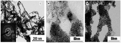 | ||
| Fig. 15 TEM images of Pd nanostructures formed by hydrazine vapour treatment of a multicomponent hexagonal mesophase made of (a) cetyl trimethylammonium bromide (CTAB) (b) sodium dodecyl sulphate (SDS) and (c) cetylpyridinium chloride (CPC). Reproduced from ref. 71 with permission from the Centre National de la Recherche Scientifique (CNRS) and The Royal Society of Chemistry. | ||
Moreover, the morphology of Pd nanostructures could be tuned by using CO as a reducing agent in place of hydrazine as shown in Fig. 16. In a typical synthesis, the Pd salts such as Pd2(DBA)3 or Pd(OAc)2 or Pd(acac)2 were dissolved in toluene and this solution was used to make the swollen liquid crystals (SLCs) with cetyl trimethylammonium bromide (CTAB) or sodium dodecyl sulphate (SDS).70 Pd nanostructures were prepared by bubbling CO through the samples and extracted using 2-propanol. Surfactant plays a very important role in defining the final morphology of Pd nanostructures. When sodium dodecyl sulphate (SDS) was used as surfactant, then spherical Pd nanoparticles were formed, while Pd ultra-thin, uniform and hexagonal nanosheets were formed when cetyl trimethylammonium bromide (CTAB) was used as the surfactant as shown in Fig. 17. It might be due to the preferential adsorption of cetyl trimethylammonium bromide (CTAB) on one of the facets of the Pd nuclei and thus facilitating the nanostructures to grow along other facets.71
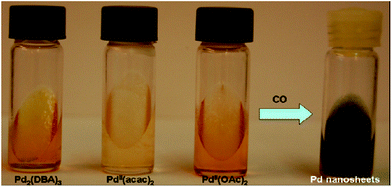 | ||
| Fig. 16 Cetyl trimethylammonium bromide (CTAB)-based hexagonal mesophases containing Pd complexes (1.5 × 10⁻³ M in the oil phase) before and after the reaction with CO. Reprinted with permission from ref. 63. Copyright 2007 American Chemical Society. | ||
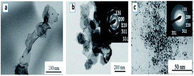 | ||
| Fig. 17 TEM images of (a and b) Pd nano sheets that were prepared by exposing the mesophases containing Pd complexes in the oil phase of water/toluene/cetyl trimethylammonium bromide (CTAB) to CO (c) TEM images of palladium nanoparticles prepared by the reaction of CO with Pd2(DBA)3 in sodium dodecyl sulphate (SDS)-based hexagonal mesophase. Reprinted with permission from ref. 70. Copyright 2007 American Chemical Society. | ||
Metal salts were dissolved in the aqueous medium to prepare mesophases doped with the metal ions that were reduced using various radiolytic and photolytic methods.
![[thin space (1/6-em)]](https://www.rsc.org/images/entities/char_2009.gif) :
:![[thin space (1/6-em)]](https://www.rsc.org/images/entities/char_2009.gif) surfactant (ncosurfactant
surfactant (ncosurfactant![[thin space (1/6-em)]](https://www.rsc.org/images/entities/char_2009.gif) :
:![[thin space (1/6-em)]](https://www.rsc.org/images/entities/char_2009.gif) nsurfactant between 0.78 to 0.91) were synthesized and irradiated using electron beam. From the TEM images (Fig. 18) it was concluded that the length of Pd nanowires increased with the increase in the amount of cosurfactant. The nanowires were formed due to the confinement effect that was provided by the mesophases. This was proved when only spherical Pd nanoparticles were formed in emulsions containing cetyl trimethylammonium bromide (CTAB), 0.1 M Pd(II) in water and cyclohexane (pentanol-free sample) or pentanol (cyclohexane-free sample) as shown in Fig. 19.72
nsurfactant between 0.78 to 0.91) were synthesized and irradiated using electron beam. From the TEM images (Fig. 18) it was concluded that the length of Pd nanowires increased with the increase in the amount of cosurfactant. The nanowires were formed due to the confinement effect that was provided by the mesophases. This was proved when only spherical Pd nanoparticles were formed in emulsions containing cetyl trimethylammonium bromide (CTAB), 0.1 M Pd(II) in water and cyclohexane (pentanol-free sample) or pentanol (cyclohexane-free sample) as shown in Fig. 19.72
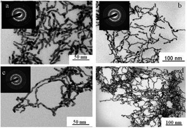 | ||
Fig. 18 TEM images of palladium nanowires formed in hexagonal mesophases using electron beam irradiation with different cosurfactant![[thin space (1/6-em)]](https://www.rsc.org/images/entities/char_2009.gif) : :![[thin space (1/6-em)]](https://www.rsc.org/images/entities/char_2009.gif) surfactant (ncosurfactant surfactant (ncosurfactant![[thin space (1/6-em)]](https://www.rsc.org/images/entities/char_2009.gif) : :![[thin space (1/6-em)]](https://www.rsc.org/images/entities/char_2009.gif) nsurfactant) molar ratio (a) 0.78 (b) 0.85 (c and d) 0. Reprinted with permission from ref. 72. Copyright 2009 American Chemical Society. nsurfactant) molar ratio (a) 0.78 (b) 0.85 (c and d) 0. Reprinted with permission from ref. 72. Copyright 2009 American Chemical Society. | ||
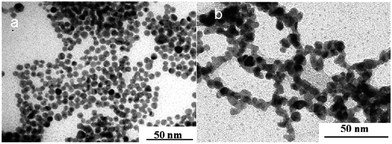 | ||
| Fig. 19 TEM images of palladium nanoparticles obtained by irradiation using ternary system containing cetyl trimethylammonium bromide (CTAB), 0.1 M Pd in water and (a) cyclohexane (pentanol-free sample) (b) pentanol (cyclohexane-free sample). Reprinted with permission from ref. 72. Copyright 2009 American Chemical Society. | ||
Interestingly, the cetyl trimethylammonium bromide (CTAB) mesophases doped with Pd(NH3)4Cl2 as described above yielded Pd-nanoballs when the mesophases were irradiated with γ-radiation instead of electron beam.76
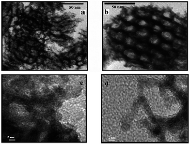 | ||
| Fig. 20 TEM and HRTEM images of (a and c) platinum nanonets (PtNNs) and (b and d) platinum nanoballs (PtNBs) synthesized in swollen liquid crystals (SLCs). Reprinted with permission from ref. 73. Copyright 2013 American Chemical Society. | ||
Porous Pt nanoballs made of connecting wires as shown in Fig. 21 can be synthesized using radiolysis in water containing phase of swollen liquid crystals (SLCs). Mesophase was prepared using cetyl trimethylammonium bromide (CTAB) as surfactant, tetraammineplatinum(II) Pt(NH3)4Cl2 as metal salted medium and sample were exposed to γ-irradiation.
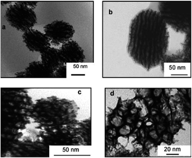 | ||
| Fig. 21 TEM images of porous platinum nanoballs made by connected nanowires and formed after complete reduction (16 h γ-irradiation) dose rate 3 kGy h−1. Reprinted with permission from ref. 58. Copyright 2007 American Chemical Society. | ||
5.2. Bimetallic nanostructures
Swollen liquid crystals (SLCs) can be doped with more than one metal salt and then chemical or radiolytic methods can be used for making bi-metallic nanostructures. Mesophases were doped with Pd and Pt salts by completely or partially replacing NaCl in aqueous medium and cetyl trimethylammonium bromide (CTAB) or cetyltrimethylammonium chloride (CTAC) or cetylpyridinium bromide (CPBr) were used as surfactants. These mesophases were then exposed to γ-radiations (dose rate 1.85 kGy h−1) and irradiation time 5 h (9.25 kGy), 12 h (22.2 kGy), 24 h (44.4 kGy) and 48 h (88.8 kGy) to yield bi-metallic Pt–Pd nanostructures.55Interestingly core–shell nanostructures were formed when mesophases simultaneously doped with Pd and Au salts were exposed to γ-radiation (60Co panoramic source: dose rate 2.2 kGy h−1) and dose 22 kGy and 9 kGy.59 Cetyl trimethylammonium bromide (CTAB) was used as surfactant, cyclohexane as the oil phase and tetraamminepalladium(II) Pd(NH3)4Cl2 and ethylenediamine gold(III) [Au(en)2]Cl3 were used as metal salts.59
5.3. Oxide nanostructures
Zirconia needles can also be synthesized using swollen liquid crystals (SLCs) in the aqueous medium after thermal treatment.77 Swollen liquid crystals (SLCs) formed of cetylpyridinium chloride (CTPCl) doped with zirconium sulfate colloids (ZSC) were used to synthesize the zirconia needles having length up to 2 cm.78Zirconia micro needles as shown in Fig. 22 and 23 can be synthesized in swollen liquid crystals (SLCs) by mixing the proper ratio of aqueous solution of zirconium colloids (precursor), cetylpyridinium chloride (surfactant), cyclohexane (swelling agent) and 1-pentanol as co-surfactant. The morphology of the Zr needles was controlled by swollen liquid crystals (SLCs) templating.71
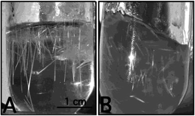 | ||
| Fig. 22 Photographs (A and B) of the reaction vessel containing Zr needles. Reprinted with permission from ref. 78. Copyright 2004 American Chemical Society. | ||
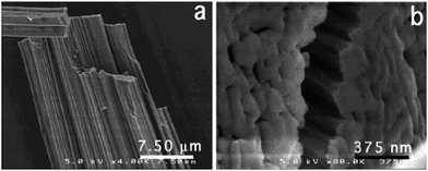 | ||
| Fig. 23 SEM images of Zr needles (a) and close view of cross section (b). Reprinted with permission from ref. 78. Copyright 2004 American Chemical Society. | ||
5.4. Polymer nanostructures and their nanocomposites
SLCs can be used as versatile soft template for the synthesis of different polymer nanostructures. Different nanostuctures like open vesicles and spindles as shown in Fig. 24 of poly(3,4-ethylenedioxythiophene) (PEDOT) were synthesized using swollen liquid crystals (SLCs).54 3,4-Ethylenedioxythiophene (EDOT) monomer was entrapped in the oil phase whereas FeCl3 (oxidant) was entrapped in the aqueous phase.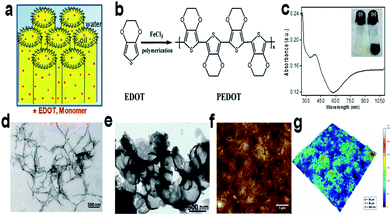 | ||
| Fig. 24 (a) Hexagonal mesophases doped with 3,4-ethylenedioxythiophene (EDOT) monomer. (b) Schematic representation of chemical oxidative polymerization of 3,4-ethylenedioxythiophene (EDOT) using FeCl3 as chemical oxidant. (c) Absorption spectrum of ethanolic solution of poly(3,4-ethylenedioxythiophene) (PEDOT) nanospindles. Inset: photograph of doped swollen hexagonal phases synthesized in presence of 0.3 M NaCl. (i) Transparent gel before polymerization and (ii) dark blue gel after polymerization by FeCl3. (d) Transmission electron micrograph (TEM) of poly(3,4-ethylenedioxythiophene) (PEDOT) nanospindles synthesized in presence of 0.3 M NaCl. (e) TEM image of poly(3,4-ethylenedioxythiophene) (PEDOT) vesicles synthesized in presence of 0.1 M NaCl. (f) Typical AFM topographic image of poly(3,4-ethylenedioxythiophene) (PEDOT) nanospindles extracted from mesophases and deposited onto ZnSe substrate. (g) The corresponding 3D AFM image of poly(3,4-ethylenedioxythiophene) (PEDOT) nanostructures. Reprinted by permission from Macmillan Publishers Ltd: Scientific Reports,79 copyright (2015). | ||
Polypyrrole (PPy) nanoparticles were prepared using lamellar mesophases by the reaction between mesophase (A) containing pyrrole and mesophase (B) containing ammonium peroxydisulfate.80 The mesophases were poured over each other and the reaction occurred by natural diffusion leading to the formation of polypyrrole (PPy) nanoparticles as shown in Fig. 25. Spherical nanoparticles of polypyrrole were formed and these were deposited in the form of a film using spin coating and then used as substrate for the deposition of ZnO nanostructures.80
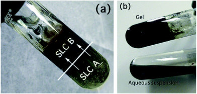 | ||
| Fig. 25 Synthesis of polypyrrole (PPy) nanoparticles in lamellar swollen liquid crystals (a) using swollen liquid crystals (SLCs) containing the pyrrole (A) and the swollen liquid crystals (SLCs) containing ammonium peroxydisulfate (B); (b) product at end of reaction (top) and polypyrrole (PPy) nanoparticles obtained after extraction (bottom). Reprinted with permission from ref. 80. Copyright 2010 American Chemical Society. | ||
Different polyaniline nanostructures (PANI-NS) can also be synthesized using aniline or aniline hydrochloride monomer trapped in oil phase or in aqueous phase respectively of swollen liquid crystals (SLCs). The trapped monomer were oxidized using ammonium persulphate as oxidant under different mixing (M) and diffusion (D) conditions. Different ways of polymerization lead to the formation of spherical and one dimensional polyaniline nanostructures (PANI-NS) as shown in Fig. 26 and 27.77,81
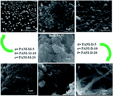 | ||
| Fig. 26 FESEM images of bulk-polyaniline (PANI) (prepared without swollen liquid crystals (SLCs)) and nanostructured-PANI samples M = mixed, D = diffusion conditions, 5, 10, 20 is the aniline/cyclohexane (volume/volume ratio) in oil phase of swollen liquid crystals (SLCs).77 Reproduced with permission from Wiley-VCH. | ||
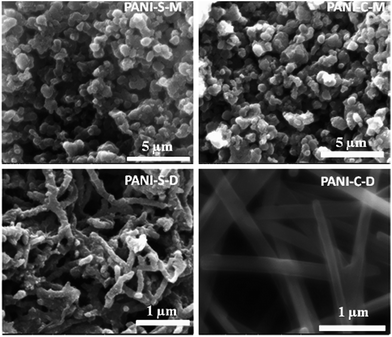 | ||
| Fig. 27 FESEM images of polyaniline nanostructures (PANI-NS) prepared under different conditions using aniline hydrochloride monomer in aqueous phase of swollen liquid crystals (SLCs) [C = cetyl trimethylammonium bromide (CTAB), S = sodium dodecyl sulphate (SDS) as surfactants]. Reproduced from ref. 81 with permission from Elsevier. | ||
The possible proposed mechanism for different polyaniline nanostructures (PANI-NS) formations is given Fig. 28. It is demonstrated that under mixed conditions, 0-D polyaniline (PANI) nanostructures were formed due to fast rate of polymerization and on the other hand, under diffusion conditions, 1-D polyaniline (PANI) nanostructures were formed due to slow rate of polymerization.
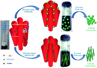 | ||
| Fig. 28 Proposed mechanism for the formation of 0-D and 1-D polyaniline (PANI) nanostructures in swollen liquid crystals (SLCs).77 Reproduced with permission from Wiley-VCH. | ||
The aniline (AN) or aniline hydrochloride (AN·HCl) monomer in oil phase or aqueous phase respectively of swollen liquid crystals (SLCs) can also be polymerized using hydrogen hexachloroplatinate (H2PtCl6·6H2O) metal salt as oxidizing agent for polyaniline (PANI)–Pt nanocomposites synthesis.52 The synthesized polyaniline (PANI)–Pt nanostructures were characterized using SEM as shown in Fig. 29 and have spherical or wire like morphology that depends upon the way of mixing (M) or diffusion (D) of the monomer with metal salt as oxidant, both confined in swollen liquid crystals (SLCs).
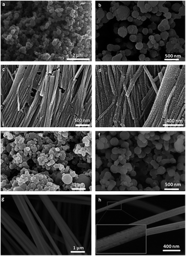 | ||
| Fig. 29 FESEM images of PANI–Pt nanocomposites (a and b) AN–Pt–M, (c and d) AN–Pt–D (e and f) AN·HCl–Pt–M and (g and h) AN·HCl–Pt–D. Reproduced from ref. 52 with permission from Elsevier. | ||
The diameter of the synthesized polymer nanostructures can also be controlled by using monomer doped swollen liquid crystals (SLCs) nanotubes with different swelling ratio (oil/water ratio) as shown in Fig. 30. Cyclohexane containing 1,4-diphenylbutadyine as monomer and benzoin methyl ether (BME) as catalyst was trapped in oil phase of swollen liquid crystals (SLCs) and polymerized using UV or γ-rays at different swelling ratios (in radiolytic synthesis no initiator was used). The diameter of the poly(diphenylbutadyine) (PDPB) nanostructures can be varied from 5 to 25 nm and is directly determined by the diameter of the oil tube of the doped mesophases.82
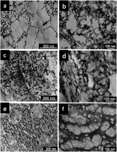 | ||
| Fig. 30 TEM images of poly(diphenylbutadyine) (PDPB) nanostructures prepared using UV irritation in mesophases with (a and b) ϕ (swelling ratio), volume ratio of oil over water (v/v) = 2.21 and Cs (total salt concentration) = 0.3 M NaCl, (c and d) ϕ = 0.98 and Cs = 0.1 M NaCl, (e and f) ϕ = 0.72 and Cs = 0 M NaCl. Reproduced from ref. 82 with permission from the Centre National de la Recherche Scientifique (CNRS) and The Royal Society of Chemistry. | ||
Goldcore–polyanilineshell composite nanowires with unique morphology were also synthesized using swollen liquid crystals (SLCs).83 The aniline monomer containing mesophase was poured over gold chloride containing mesophase and the reaction was allowed to start under slow diffusion as shown in Fig. 31.
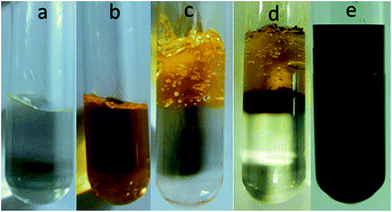 | ||
| Fig. 31 Photographs of (a) mesophase containing aniline, (b) mesophase containing gold chloride, (c) mesophases at the time of mixing, (d) mesophases after 1 h reaction and (e) mesophases after 72 h showing the completion of reaction. Reproduced from ref. 83 with permission from the Centre National de la Recherche Scientifique (CNRS) and The Royal Society of Chemistry. | ||
Goldcore–polyanilineshell composite nanowires with unique morphology with polyaniline masked gold nanowires were synthesized as shown in Fig. 32.
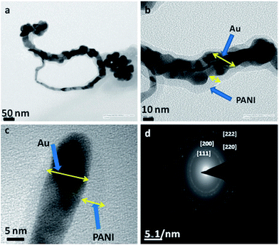 | ||
| Fig. 32 TEM images of goldcore–polyanilineshell composite nanowires synthesized using swollen liquid crystals (SLCs) (a) long nanowire and some nanoparticles, (b) high resolution image of portion of (a) where the polyaniline (PANI) shell is clearly visible, (c) end of a nanowire and (d) the selected area electron diffraction (SAED) pattern. Reproduced from ref. 83 with permission from the Centre National de la Recherche Scientifique (CNRS) and The Royal Society of Chemistry. | ||
6. Application of the nanostructured materials synthesized using swollen liquid crystals (SLCs)
The different nanostructured materials synthesized using swollen liquid crystals (SLCs) find it better application in different areas such as in sensing, electrocatalysis, photocatalysis, etc. as discussed in detail below.6.1. Alcohol electro oxidation
Pd nanoplates synthesized using swollen liquid crystals (SLCs) in solution by slow reduction via radiolysis supported with poly diphenylbutadiyne (PDPB) nanofibers exhibit highly active, stable catalysis for the ethanol oxidation.84 The nanocomposites showed excellent catalytic activity in direct alcohol oxidation due to its high surface area, better conductivity and mass transport. The nanocomposites was synthesized using swollen liquid crystals (SLCs) containing 1,4-diphenylbutadiyne (DPB) as monomer and PdII(acac)2 as metal precursors source and the electro catalyst showed better electro catalytic activity. Comparison is made among other Pd nanostructures as in Table 1. It's shown that the Pd nanoplates synthesized using SLCs showed better electrocatalytic activity among other Pd nanostructures such as Pd nanowires, Pd nanoballs.84 Hence conducting polymers supported Pd nanostructures synthesized using swollen liquid crystals (SLCs) acts as better electrocatalyst for fuel cells applications.| Materials (after 50 cycles) | jpf (forward anodic peak current density) [A cm−2 (mg−1 of Pd)] | jpf/jpb(backward peak current density) | Eonset onset potentials of the faradaic current (V vs. Hg/HgO) | Epf (potentials corresponding to the maxima of the forward peak) (V vs. Hg/HgO) | Epb (backward peak currents) (V vs. Hg/HgO) | Ref. |
|---|---|---|---|---|---|---|
| Pd nanoplates + PDPB nanofibers | 4.5 | 1.95 | −0.570 | −0.174 | −0.297 | 84 |
| Pd nanowires + Nafion | 2 | 1 | −0.664 | −0.166 | −0.278 | 72 |
| Pd nanoballs + Nafion | 0.12 | 1.17 | −0.550 | −0.151 | −0.296 | 76 |
Bimetallic nanostructures have often better performance in sensing, catalysis, electrolysis and storage application than monometallic nanostructures.85–87 Bimetallic Pdshell–Aucore nanostructures were also synthesized in soft template confinement provided by the cetyl trimethylammonium bromide (CTAB) surfactant using radiolytic method for synthesis. The synthesized nanostructures showed application in fuel cells with very good electrochemical activity and stability as shown in Fig. 33.59
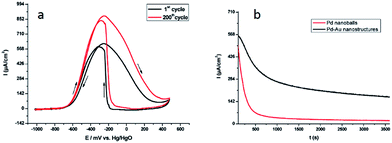 | ||
| Fig. 33 (a) Superposition of the first (black solid line curve) and the 200th (red solid line curve) cyclic voltammetric runs associated with the electrocatalytic oxidation of 1 M EtOH in 1 M KOH with continuous cycling of the electrode potential. The working electrode was a glassy carbon disk modified with the bimetallic Pd–Aumeso nanostructures synthesized in the mesophase. The reference electrode was an Hg/HgO (1 M KOH) electrode. The scan rate was 50 mV s−1 (b) chronoamperometric curves for ethanol electrooxidation at −0.3 V vs. Hg/HgO on a glassy carbon electrode modified with bimetallic Pd–Aumeso nanostructures synthesized in a hexagonal mesophase (black curve) or Pd nanoballs (red curve). The solution was 1 M KOH + 1 M ethanol. The Pd nanoballs synthesized using swollen liquid crystals (SLCs) also exhibited better electro catalytic activity for ethanol oxidation in 1 M KOH. Reprinted with permission from ref. 59. Copyright 2009 American Chemical Society. | ||
In comparison, the If (forward current)/Ib (backward current) ratio seems to be better 1.05 obtained with Pd–Aumeso nanostructures Pd@Au/C nanostructures (0.69).88 Hence the Pd–Aumeso nanostructures synthesized using swollen liquid crystals (SLCs) shows better performance for ethanol electrooxidation.
6.2. Pollutant degradation
Catalytic activity of metal nanostructures synthesized using swollen liquid crystals (SLCs) were also explored for pollutant degradation. Platinum nanonets (PtNNs) and platinum nanoballs (PtNBs) were synthesized in swollen liquid crystals (SLCs) using radiolysis.73 In their typical synthesis swollen liquid crystals (SLCs) were doped with Pt(NH3)4Cl2. Swollen liquid crystals (SLCs) containing Pt salt was exposed with γ-rays and dose rate was 40 kGy for platinum nanonets (PtNNs) and 80 kGy for platinum nanoballs (PtNBs). The synthesized Pt nanostructures were studied for their catalytic degradation to hexacyanoferrate(III) and p-nitrophenol (PNP) as shown in Fig. 34.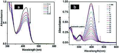 | ||
| Fig. 34 (a) Time dependent UV-vis spectra at different reaction times for the electron transfer reaction between hexacyanoferrate(III) and sodium thiosulfate in the presence of platinum nanoballs (PtNBs) (b) UV-vis absorption spectra at different time intervals indicate the disappearance of the peak of p-nitrophenolate anion at 400 nm due to the reduction of p-nitrophenol (PNP) to p-aminophenol (PAP) by NaBH4 in the presence of platinum nanonets (PtNNs). Reprinted with permission from ref. 73. Copyright 2013 American Chemical Society. | ||
Pd nanowires synthesized using swollen liquid crystals (SLCs) as soft template also exhibited better catalytic activity for p-nitrophenol reduction among others as shown in comparison Table 2.89
| Catalyst/support | Average size (nm) | 4-NP concentration (mM) | Number of moles of catalyst | Apparent rate constant (k) (s−1) | Normalized rate constanta (s−1) | Ref. |
|---|---|---|---|---|---|---|
| a Rate constant per moles of catalyst available per mM of 4-NP. | ||||||
| Pd-PEDOT/PSS | 24 | 0.001 | 1.879 × 10⁻⁵ | 65.8 × 10⁻³ | 0.035 × 10² | 93 |
| Microgel-Pd | 3.8 | 0.1 | 1.879 × 10⁻⁶ | 1.5 × 10⁻³ | 0.79 × 10² | 94 |
| SPB-Pd | 2.4 | 0.1 | 2.819 × 10⁻⁷ | 4.41 × 10⁻³ | 15.63 × 10² | 95 |
| PAMAM-Pd | 1.6 | 0.3 | 9.96 × 10⁻³ | 3.59 × 10⁻³ | 0.001 × 10² | 96 |
| PPI-Pd | 2 | 0.3 | 1.97 × 10⁻³ | 407 × 10−3 | 0.61 × 10² | 96 |
| Ag@Pd/Fe3O4 | 16.9 ± 1.3 | 0.15 | 1.78 × 10⁻⁵ | 33 × 10−3 | 2.77 × 10² | 97 |
| PPy/TiO2/Pd | 2 | 0.1 | 1.64 × 10⁻² | 1.22 × 10⁻³ | 7.4 × 10⁻³ | 98 |
| SBA-15/Pd | 8 | 0.001 | 1.87 × 10⁻² | 24 × 10−3 | 1.2 × 10⁻³ | 99 |
| CeO2/Pd | 3–5 | 0.07 | 2.34 × 10⁻⁴ | 8 × 10⁻³ | 0.02 × 10² | 100 |
| Protein/Pd | 2.85 ± 0.5 | 0.1 | 4.69 × 10⁻³ | 48 × 10−3 | 0.10 × 10² | 101 |
| Pd cluster | 4–5 | 0.2 | 1.56 × 10⁻³ | 0.133 × 10⁻³ | 1.69 × 10⁻² | 102 |
| Al2O3/Pd | 6 ± 0.5 | 0.1 | 1.87 × 10⁻³ | 111 × 10−3 | 0.05 × 10² | 103 |
| Pd nanowires | 5 ± 0.9 | 1.6 | 4.69 × 10⁻⁵ | 45.9 × 10⁻³ | 15.63 × 10² | 89 |
Goldcore–polyanilineshell composite nanowires were also reported first time in the literature.83 In typical synthesis of this unique nanocomposites the aniline monomer was trapped inside the swollen liquid crystals (SLCs) and on other hand, gold chloride metal salt as precursor was also trapped inside the swollen liquid crystals (SLCs) in different Pyrex glass tubes. After swollen liquid crystals (SLCs) synthesis, the both phases were allowed for slow diffusion over each other and due to polymerization, goldcore–polyanilineshell was synthesized. The synthesized nanocomposites showed better performance for dye degradation applications as shown in Table 3 and Fig. 35.
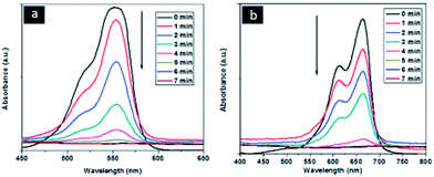 | ||
| Fig. 35 Time dependent UV-visible spectra of rhodamine B (RhB) and methylene blue (MB) showing the progress of dye reduction by NaBH4 nanocomposite in presence of goldcore–polyanilineshell nanocomposites recorded at 1 min intervals. Reproduced from ref. 83 with permission from the Centre National de la Recherche Scientifique (CNRS) and The Royal Society of Chemistry. | ||
6.3. Coupling reactions
Palladium nanowires synthesized using swollen liquid crystals (SLCs) as structure directing template were shown better catalytic activity in carbon–carbon (C–C) coupling organic reactions.89 The synthesized Pd nanowires using swollen liquid crystals (SLCs) were used as catalysts in Suzuki–Miyaura coupling reactions and showed better performance among others as shown in Table 4. The progress of the reaction was initially monitored using TLC and the final extracted product was studied using NMR technique.| Catalyst/support | Base | Average size (nm) | Yield (%) | Temperature/°C | (Solvent) | Reaction time/h | Catalyst conc./mol% | Ref. |
|---|---|---|---|---|---|---|---|---|
| PVP stabilized Pd nanoparticles | Na3PO4 | 3–4 | 92 | Reflux | 40% EtOH aqueous solution | 12 h | 0.3 mol% pd | 107 |
| Polyaniline/Pd nanocomposites | K3PO4 | 4–6 | 85 | 100 °C | 1,4-Dioxane | 15 h | 1.0 mol% | 108 |
| Polyaniline/Pd nanocomposites | K2CO3 | 3.1 ± 0.9 | 86 | 90 °C | H2O | 4 h | 0.01 mol% PANI–Pd | 109 |
| Microgel supported Pd nanoparticles | K2CO3 | 11.6 ± 2.1 | 98 | 90 °C | H2O | 1 h | 0.1 mol% Pd | 110 |
| Pd nanowires | Sodium t-butoxide | 5 (diameter) | 99 | RT | H2O | 24 h | 6.5 mol% Pd | 111 |
| Hollow Pd spheres | K3PO4 | 300 | 99 | 78 °C reflux | EtOH | 3 h | 3 mol% Pd | 112 |
| Pd nanorods | K3PO4 | 20 (diameter) | 92 | 85 °C reflux | EtOH![[thin space (1/6-em)]](https://www.rsc.org/images/entities/char_2009.gif) : :![[thin space (1/6-em)]](https://www.rsc.org/images/entities/char_2009.gif) H2O (4 H2O (4![[thin space (1/6-em)]](https://www.rsc.org/images/entities/char_2009.gif) : :![[thin space (1/6-em)]](https://www.rsc.org/images/entities/char_2009.gif) 1) 1) |
4 h | 1.6 mol% | 113 |
| Pd nanowires | K2CO3 | 3–8 (diameter) | 80 | 90 °C | Toluene | 9 h | 0.01 mol% | 89 |
6.4. Glucose bio sensing
Spherical and one dimensional polyaniline (PANI) nanostructures were synthesized using swollen liquid crystals (SLCs) as soft templates.77 The glucose biosensing applications of the synthesized nanostructures were studied and the polyaniline (PANI) nanostructures showed better sensing property than bulk polyaniline (PANI) (prepared without any template) as shown in Fig. 36.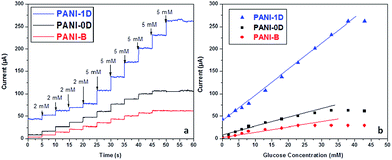 | ||
| Fig. 36 (a) Chronoamperometric response of polyaniline (PANI) nanostructures synthesized using swollen liquid crystals (SLCs) and bulk polyaniline (PANI) with varying concentration of glucose in PBS buffer (pH = 7.2) (b) calibration curves corresponding to the chronoamperometric glucose detection. Adapted with permission from ref. 90, copyright 2015, Biointerface Research in Applied Chemistry. | ||
6.5. Photocatalysis
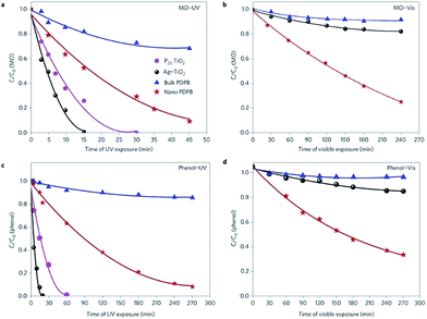
One-dimensional poly(diphenylbutadiyne) nanostructures were synthesized by photopolymerization using swollen liquid crystals (SLCs) as soft templating confinement. The synthesized nanostructures have high photocatalytic activity under visible light without the assistance of sacrificial reagents or precious metal co-catalysts as shown in Fig. 37.91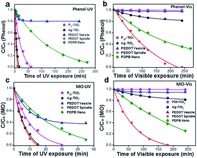 | ||
| Fig. 37 (a–d) Photocatalytic degradation of methyl orange (a and b) and phenol (c and d) in the presence of commercial P25 TiO2, Ag–TiO2 and the synthesized bulk poly(diphenylbutadyine) (PDPB) and nano poly(diphenylbutadyine) (PDPB). (a and c) Degradation carried out under visible light (>450 nm). (b and d) Degradation carried out under ultraviolet light. The concentrations of nano poly(diphenylbutadyine) (PDPB), bulk poly(diphenylbutadyine) (PDPB), Ag–TiO2 and TiO2 in water were 1 mg mL−1. Initial concentrations C0 were 6 × 10⁻⁵ mol L−1 for methyl orange (MO) and 3.7 × 10⁻³ mol L−1 for phenol. The legend in figure (a) applies to all panels. Reprinted by permission from Macmillan Publishers Ltd: Nature Materials,91 copyright (2015). | ||
Poly(3,4-ethylenedioxythiophene) (PEDOT) nanostructures synthesized in swollen liquid crystals (SLCs) as soft templates via chemical oxidative polymerization showed better photocatalytic activities than TiO2 as shown in Fig. 38.79 The poly(3,4-ethylenedioxythiophene) (PEDOT) nanostructures were synthesized by trapping the 3,4-ethylenedioxythiophene (EDOT) monomer inside the mesophase and FeCl3 was used as oxidant for polymerization.79
 | ||
| Fig. 38 Photocatalytic degradation of (a and b) phenol and (c and d) methyl orange (MO) in the presence of commercial P25 TiO2 and Ag–TiO2, poly(diphenylbutadyine) (PDPB) nanofibers and the synthesized poly(3,4-ethylenedioxythiophene) (PEDOT) vesicles and poly(3,4-ethylenedioxythiophene) (PEDOT) nanospindles under UV (a and c) and visible light (>450 nm) (b and d) irradiation. The concentrations of poly(diphenylbutadyine) (PDPB) nanofibers, poly(3,4-ethylenedioxythiophene) (PEDOT) vesicles, poly(3,4-ethylenedioxythiophene) (PEDOT) nanospindles, Ag–TiO2 and TiO2 in water were 1 mg mL−1. Initial concentrations C0 were 3.7 × 10⁻³ mol L−1 for phenol and 6 × 10⁻⁵ mol L−1 for methyl orange (MO). Reprinted by permission from Macmillan Publishers Ltd: Scientific Reports,79 copyright (2015). | ||
Moreover, the photo catalytic activity of poly(3,4-ethylenedioxythiophene) (PEDOT) nanospindles synthesized using SLCs is much better than bulk poly(3,4-ethylenedioxythiophene) (PEDOT) and poly(diphenylbutadyine) (PDPB) nanofibers.92
7. Future directions and prospectives
Here, we have summarized the synthesis of different nanostructures using swollen liquid crystals (SLCs). Swollen liquid crystals (SLCs) acts as an efficient and versatile template for the synthesis of nanomaterials. The stability of swollen liquid crystals (SLCs) depends upon the chemical nature of the trapped components inside the nano channels, pH, temperature etc. It is also shown that using swollen liquid crystals (SLCs), different types of nanostructures can be synthesized due to change of experimental parameters during swollen liquid crystals (SLCs) preparation. Hence, swollen liquid crystals (SLCs) as nano channels can be used as reacting media to perform different kind of reactions inside these channels. Nanostructures synthesis can also be done inside these nano channels. Swollen liquid crystals (SLCs) can be used for the synthesis of porous, zero dimensional, one dimensional nanostructures with tunable properties. These synthesized nanostructures have different applications such as in catalysis, electrocatalysis, sensing, fuel cells etc. The swollen liquid crystals (SLCs) will open up a new area of research because the reactions can be performed in aqueous phase or organic phase or potentially in both phases or eventually at the interface between the two phases. This should lead to the control of the morphology and then to the optimization of the properties of the as-synthesized nanomaterials.Acknowledgements
S. D. is thankful to The Scientific and Technological Research Council of Turkey (TÜBİTAK) to support under 2216 fellowship grant for international Post-Doctoral researchers.References
- C. R. Martin, Chem. Mater., 1996, 8, 1739–1746 CrossRef CAS.
- X. Lu, C. Wang and Y. Wei, Small, 2009, 5, 2349–2370 CrossRef CAS PubMed.
- J. D. Schiffman and C. L. Schauer, Polym. Rev., 2008, 48, 317–352 CrossRef CAS.
- J. C. Hulteen and C. R. Martin, J. Mater. Chem., 1997, 7, 1075–1087 RSC.
- G. Cao and D. Liu, Adv. Colloid Interface Sci., 2008, 136, 45–64 CrossRef CAS PubMed.
- X. Chen and S. S. Mao, Chem. Rev., 2007, 107, 2891–2959 CrossRef CAS PubMed.
- G. Cao and D. Liu, Adv. Colloid Interface Sci., 2008, 136, 45–64 CrossRef CAS PubMed.
- M. A. Lopez-Quintela, Curr. Opin. Colloid Interface Sci., 2003, 8, 137–144 CrossRef CAS.
- X. Chen and S. S. Mao, Chem. Rev., 2007, 107, 2891–2959 CrossRef CAS PubMed.
- H. D. Tran, D. Li and R. B. Kaner, Adv. Mater., 2009, 21, 1487–1499 CrossRef CAS.
- P. F. Siril, L. Ramos, P. Beaunier, P. Archirel, A. Etcheberry and H. Remita, Chem. Mater., 2009, 21, 5170–5175 CrossRef CAS.
- L. Ramos and P. Fabre, Langmuir, 1997, 13, 682–686 CrossRef CAS.
- E. Pena dos Santos, M. S. Tokumoto, G. Surendran, H. Remita, C. Bourgaux, P. Dieudonné, E. Prouzet and L. Ramos, Langmuir, 2005, 21, 4362–4369 CrossRef PubMed.
- L. Ramos and C. Ligoure, Langmuir, 2008, 24, 5221–5224 CrossRef CAS PubMed.
- K. Holmberg, J. Colloid Interface Sci., 2004, 274, 355–364 CrossRef CAS PubMed.
- J. N. Israelachvili, D. J. Mitchell and B. W. Ninham, J. Chem. Soc., Faraday Trans. 2, 1976, 72, 1525–1568 RSC.
- J. Israelachvili, Colloids Surf., A, 1994, 91, l–8 CrossRef.
- M. Salim, H. Minamikawa, A. Sugimura and R. Hashim, MedChemComm, 2014, 5, 1602–1618 RSC.
- J. P. Hill, L. K. Shrestha, S. Ishihara, Q. Ji and K. Ariga, Molecules, 2014, 19, 8589–8609 CrossRef PubMed.
- A. Brizard, M. Stuart, K. Bommel, A. Friggeri, M. Jong and J. Esch, Angew. Chem., Int. Ed., 2008, 47, 2063–2066 CrossRef CAS PubMed.
- G. Zhou, Y. Chen, J. Yang and S. Yang, J. Mater. Chem., 2007, 17, 2839–2844 RSC.
- B. Sun, G. Zhou and H. Zhang, Prog. Solid State Chem., 2016, 44, 1–19 CrossRef CAS.
- X. Wang, J. Feng, Y. Bai, Q. Zhang and Y. Yin, Chem. Rev., 2016, 116, 10983–11060 CrossRef CAS PubMed.
- Q. Liu, Z. Sun, Y. Dou, J. H. Kim and S. X. Dou, J. Mater. Chem. A, 2015, 3, 11688–11699 CAS.
- S. Saliba, C. Mingotaud, M. L. Kahn and J. D. Marty, Nanoscale, 2013, 5, 6641–6661 RSC.
- F. C. Frank, Discuss. Faraday Soc., 1958, 25, 19–28 RSC.
- A. Humpert, A. J. Masters and M. P. Allen, Eur. Phys. J.: Spec. Top., 2016, 225, 1723–1732 CrossRef CAS.
- P. S. Pershan, Phys. Today, 2008, 35, 34–39 CrossRef.
- B. J. Forrest and L. W. Reeves, Chem. Rev., 1981, 81(1), 1–14 CrossRef CAS.
- W. Bryks, M. Wette, N. Velez, S. W. Hsu and A. R. Tao, J. Am. Chem. Soc., 2014, 136, 6175–6178 CrossRef CAS PubMed.
- S. Peng, Q. Guo, T. C. Hughes and P. G. Hartley, Langmuir, 2013, 30, 866–872 CrossRef PubMed.
- T. M. Dellinger and P. V. Braun, Chem. Mater., 2004, 16, 2201–2207 CrossRef CAS.
- P. S. Pershan, Phys. Today, 1982, 35, 34–39 CrossRef CAS.
- C. Wang, D. Chen and X. Jiao, Sci. Technol. Adv. Mater., 2009, 10, 023001 CrossRef PubMed.
- H. J. Coles and M. N. Pivnenko, Nature, 2005, 436, 997–1000 CrossRef CAS PubMed.
- J. Li, S. Gauza and S. T. Wu, J. Appl. Phys., 2004, 96, 19–24 CrossRef CAS.
- S. Bonazzi, M. Capobianco, M. M. D. Morais, A. Garbesi, G. Gottarelli, P. Mariani, M. G. P. Bossi, G. P. Spada and L. Tondelli, J. Am. Chem. Soc., 1991, 113(15), 5809–5816 CrossRef CAS.
- C. M. Paleos and D. Tsiourvas, Angew. Chem., Int. Ed. Engl., 1995, 34, 1696–1711 CrossRef CAS.
- T. Oka and N. Ohta, Langmuir, 2016, 32, 7613–7620 CrossRef CAS PubMed.
- C. Wang, D. Chen and X. Jiao, Sci. Technol. Adv. Mater., 2009, 10, 023001 CrossRef PubMed.
- W. Abidi, B. Pansu, R. Krishnaswamy, P. Beaunier, H. Remita and M. Imperor-Clerc, RSC Adv., 2011, 1, 434–439 RSC.
- W. Abidi, P. Selvakannan, Y. Guillet, I. Lampre, P. Beaunier, B. Pansu, B. Palpant and H. Remita, J. Phys. Chem. C, 2010, 114, 14794–14803 CAS.
- T. Kijima, T. Ikeda, M. Yada and M. Machida, Langmuir, 2002, 18, 6453–6457 CrossRef CAS.
- L. Huang, H. Wang, Z. Wang, A. Mitra, K. N. Bozhilov and Y. Yan, Adv. Mater., 2002, 14, 61 CrossRef CAS.
- H. Kawasaki, M. Uota, T. Yoshimura, D. Fujikawa, G. Sakai, M. Annaka and T. Kijima, Langmuir, 2005, 21, 11468–11473 CrossRef CAS PubMed.
- C. Kresge, M. Leonowicz, W. Roth, J. Vartuli and J. Beck, Nature, 1992, 359, 710–712 CrossRef CAS.
- L. Ramos and C. Ligoure, Langmuir, 2008, 24, 5221–5224 CrossRef CAS PubMed.
- G. Surendran, M. S. Tokumoto, E. Pena dos Santos, H. Remita, L. Ramos, P. J. Kooyman, C. V. Santilli, C. Bourgaux, P. Dieudonné and E. Prouzet, Chem. Mater., 2005, 17, 1505–1514 CrossRef CAS.
- G. Surendran, M. S. Tokumoto, E. P. Santos, H. Remita, L. Ramos, P. J. Kooyman, C. V. Santilli, C. Bourgaux, P. Dieudonne and E. Prouzet, Chem. Mater., 2005, 17, 1505–1514 CrossRef CAS.
- L. Ramos and P. Fabre, Langmuir, 1997, 13, 682–686 CrossRef CAS.
- E. Pena dos Santos, M. S. Tokumoto, G. Surendran, H. Remita, C. Bourgaux, P. Dieudonné, E. Prouzet and L. Ramos, Langmuir, 2005, 21, 4362–4369 CrossRef PubMed.
- S. Dutt and P. F. Siril, Synth. Met., 2015, 209, 82–90 CrossRef CAS.
- E. Eiser, F. Bouchama, M. B. Thathagar and G. Rothenberg, ChemPhysChem, 2003, 4, 526–528 CrossRef CAS PubMed.
- S. Ghosh, H. Remita, L. Ramos, A. Dazzi, A. Deniset-Besseau, P. Beaunier, F. Goubard, P.-H. Aubert, F. Brisset and S. Remita, New J. Chem., 2014, 38, 1106–1115 RSC.
- A. Lehoux, L. Ramos, P. Beaunier, D. B. Uribe, P. Dieudonné, F. Audonnet, A. Etcheberry, M. José-Yacaman and H. Remita, Adv. Funct. Mater., 2012, 22, 4900–4908 CrossRef CAS.
- T. Redjala, G. Apostolecu, P. Beaunier, M. Mostafavi, A. Etcheberry, D. Uzio, C. Thomazeau and H. Remita, New J. Chem., 2008, 32, 1403–1408 RSC.
- L. Ramos, P. Fabre and R. Ober, Eur. Phys. J. B, 1998, 1, 319–326 CrossRef CAS.
- G. Surendran, L. Ramos, B. Pansu, E. Prouzet, P. Beaunier, F. Audonnet and H. Remita, Chem. Mater., 2007, 19, 5045–5048 CrossRef CAS.
- F. Ksar, L. Ramos, B. Keita, L. Nadjo, P. Beaunier and H. Remita, Chem. Mater., 2009, 21, 3677–3683 CrossRef CAS.
- P. Fabre, C. Casagrande, M. Veyssie, V. Cabuil and R. Massart, Phys. Rev. Lett., 1990, 64, 539 CrossRef CAS PubMed.
- C. Quilliet, P. Fabre and V. Cabuil, J. Phys. Chem., 1993, 97, 287–289 CrossRef CAS.
- C. Quilliet, V. Ponsinet and V. Cabuil, J. Phys. Chem., 1994, 98, 3566–3569 CrossRef CAS.
- L. Ramos, P. Fabre and L. Fruchter, Eur. Phys. J. B, 1999, 8, 67–72 CrossRef CAS.
- L. Ramos, F. Molino and G. Porte, Langmuir, 2000, 16, 5846–5848 CrossRef CAS.
- N. Kinadjian, F. Nallet, I. Ly, A. Bentaleb, R. Backov and E. Prouzet, Liq. Cryst., 2016, 43, 615–622 CrossRef CAS.
- A. Thomas, F. Goettmann and M. Antonietti, Chem. Mater., 2008, 20, 738–755 CrossRef CAS.
- C. C. Yang, C. C. Wan and Y. Y. Wang, J. Colloid Interface Sci., 2004, 279, 433–439 CrossRef CAS PubMed.
- Q. Zhang, W. Wang, J. Goebl and Y. Yin, Nano Today, 2009, 4, 494–507 CrossRef CAS.
- H. D. Tran, D. Li and R. B. Kaner, Adv. Mater., 2009, 21, 1487–1499 CrossRef CAS.
- P. F. Siril, L. Ramos, P. Beaunier, P. Archirel, A. Etcheberry and H. Remita, Chem. Mater., 2009, 21, 5170–5175 CrossRef CAS.
- P. F. Siril, A. Lehoux, L. Ramos, P. Beaunier and H. Remita, New J. Chem., 2012, 36, 2135–2139 RSC.
- F. Ksar, G. Surendran, L. Ramos, B. Keita, L. Nadjo, E. Prouzet, P. Beaunier, A. Hagege, F. Audonnet and H. Remita, Chem. Mater., 2009, 21, 1612–1617 CrossRef CAS.
- A. M. Kalekar, K. K. K. Sharma, A. Lehoux, F. Audonnet, H. Remita, A. Saha and G. K. Sharma, Langmuir, 2013, 29, 11431–11439 CrossRef CAS PubMed.
- H. Tang, G. Meng, Q. Huang, C. Zhu, Z. Huang, Z. Li, Z. Zhang and Y. Zhang, RSC Adv., 2014, 4, 19654–19657 RSC.
- T. Arun, D. K. Chacko, A. A. Madhavan, T. Deepak, G. Anjusree, T. Sara, S. Ramakrishna, S. V. Nair and A. S. Nair, RSC Adv., 2014, 4, 1421–1424 RSC.
- G. Surendran, F. Ksar, L. Ramos, B. Keita, L. Nadjo, E. Prouzet, P. Beaunier, P. Dieudonné, F. Audonnet and H. Remita, J. Phys. Chem. C, 2008, 112, 10740–10744 CAS.
- S. Dutt and P. F. Siril, J. Appl. Polym. Sci., 2014, 131, 40800 CrossRef.
- E. P. Santos, C. V. Santilli, S. H. Pulcinelli and E. Prouzet, Chem. Mater., 2004, 16, 4187–4192 CrossRef.
- S. Ghosh, N. A. Kouame, S. Remita, L. Ramos, F. Goubard, P. H. Aubert, A. Dazzi, A. Deniset-Besseau and H. Remita, Sci. Rep., 2015, 5, 18002 CrossRef CAS PubMed.
- D. U. Lee, D. Pradhan, R. Mouawia, D. H. Oh, N. F. Heinig, K. T. Leung and E. Prouzet, Chem. Mater., 2009, 22, 218–225 CrossRef.
- S. Dutt and P. F. Siril, Mater. Lett., 2014, 124, 50–53 CrossRef CAS.
- S. Ghosh, L. Ramos, S. Remita, A. Dazzi, A. Deniset-Besseau, P. Beaunier, F. Goubard, P. H. Aubert and H. Remita, New J. Chem., 2015, 39, 8311–8320 RSC.
- S. Dutt, P. F. Siril, V. Sharma and S. Periasamy, New J. Chem., 2015, 39, 902–908 RSC.
- S. Ghosh, A. L. Teillout, D. Floresyona, P. de Oliveira, A. Hagège and H. Remita, Int. J. Hydrogen Energy, 2015, 40, 4951–4959 CrossRef CAS.
- H.-L. Jiang and Q. Xu, J. Mater. Chem., 2011, 21, 13705–13725 RSC.
- D. Wang and Y. Li, Adv. Mater., 2011, 23, 1044–1060 CrossRef CAS PubMed.
- R. P. Doherty, J. M. Krafft, C. Méthivier, S. Casale, H. Remita, C. Louis and C. Thomas, J. Catal., 2012, 287, 102–113 CrossRef CAS.
- L. D. Zhu, T. S. Zhao, J. B. Xu and Z. X. Liang, J. Power Sources, 2009, 187, 80 CrossRef CAS.
- M. Chawla, R. Kumar and P. F. Siril, J. Mol. Catal. A: Chem., 2016, 423, 126–134 CrossRef CAS.
- S. Dutt and P. F. Siril, Biointerface Res. Appl. Chem., 2015, 5(2), 937–940 Search PubMed.
- S. Ghosh, N. A. Kouamé, L. Ramos, S. Remita, A. Dazzi, A. Deniset-Besseau, P. Beaunier, F. Goubard, P. H. Aubert and H. Remita, Nat. Mater., 2015, 14, 505–511 CrossRef CAS PubMed.
- Z. Yin and Q. Zheng, Adv. Energy Mater., 2012, 2, 179–218 CrossRef CAS.
- S. Harish, J. Mathiyarasu, K. Phani and V. Yegnaraman, Catal. Lett., 2009, 128, 197–202 CrossRef CAS.
- Y. Mei, Y. Lu, F. Polzer, M. Ballauff and M. Drechsler, Chem. Mater., 2007, 19, 1062–1069 CrossRef CAS.
- K. Esumi, R. Isono and T. Yoshimura, Langmuir, 2004, 20, 237–243 CrossRef CAS PubMed.
- K. Jiang, H. X. Zhang, Y. Y. Yang, R. Mothes, H. Lang and W. B. Cai, Chem. Commun., 2011, 47, 11924–11926 RSC.
- X. Lu, X. Bian, G. Nie, C. Zhang, C. Wang and Y. Wei, J. Mater. Chem., 2012, 22, 12723–12730 RSC.
- J. Morere, M. Tenorio, M. Torralvo, C. Pando, J. Renuncio and A. Cabanas, J. Supercrit. Fluids, 2011, 56, 213–222 CrossRef CAS.
- B. Liu, S. Yu, Q. Wang, W. Hu, P. Jing, Y. Liu, W. Jia, Y. Liu, L. Liu and J. Zhang, Chem. Commun., 2013, 49, 3757–3759 RSC.
- S. Behrens, A. Heyman, R. Maul, S. Essig, S. Steigerwald, A. Quintilla, W. Wenzel, J. Bürck, O. Dgany and O. Shoseyov, Adv. Mater., 2009, 21, 3515–3519 CrossRef CAS.
- A. Halder, S. Patra, B. Viswanath, N. Munichandraiah and N. Ravishankar, Nanoscale, 2011, 3, 725–730 RSC.
- S. Arora, P. Kapoor and M. L. Singla, React. Kinet., Mech. Catal., 2010, 99, 157–165 CAS.
- Z. Gan, A. Zhao, M. Zhang, W. Tao, H. Guo, Q. Gao, R. Mao and E. Liu, Dalton Trans., 2013, 8597–8605 RSC.
- Z. J. Jiang, C. Y. Liu and L. W. Sun, J. Phys. Chem. B, 2005, 109, 1730–1735 CrossRef CAS PubMed.
- S. Xuan, Y. X. J. Wang, J. C. Yu and K. C. F. Leung, Langmuir, 2009, 25, 11835–11843 CrossRef CAS PubMed.
- B. Zhang, B. Zhao, S. Huang, R. Zhang, P. Xu and H. L. Wang, CrystEngComm, 2012, 14, 1542–1544 RSC.
- Y. Li, X. M. Hong, D. M. Collard and M. A. El-Sayed, Org. Lett., 2000, 2, 2385–2388 CrossRef CAS PubMed.
- A. Houdayer, R. Schneider, D. Billaud, J. Ghanbaja and J. Lambert, Appl. Organomet. Chem., 2005, 19, 1239–1248 CrossRef CAS.
- S. Dutt, R. Kumar and P. F. Siril, RSC Adv., 2015, 5, 33786–33791 RSC.
- J. Yang, D. Wang, W. Liu, X. Zhang, F. Bian and W. Yu, Green Chem., 2013, 15, 3429–3437 RSC.
- C. Jiang, S. Ranjit, Z. Duan, Y. L. Zhong, K. P. Loh, C. Zhang and X. Liu, Nanoscale, 2009, 1, 391–394 RSC.
- S. W. Kim, M. Kim, W. Y. Lee and T. Hyeon, J. Am. Chem. Soc., 2002, 124, 7642–7643 CrossRef CAS PubMed.
- Y. H. Chen, H. H. Hung and M. H. Huang, J. Am. Chem. Soc., 2009, 131, 9114–9121 CrossRef CAS PubMed.
| This journal is © The Royal Society of Chemistry 2017 |

