
Creep-resistant behavior of beta-polypropylene with different crystalline morphologies
Chenfei Jiaa,
Xia Liao*a,
Jingjun Zhub,
Zhu Anb,
Qiongwen Zhanga,
Qi Yanga and
Guangxian Li*a
aCollege of Polymer Science and Engineering, State Key Laboratory of Polymer Materials Engineering, Sichuan University, Chengdu, Sichuan 610065, China. E-mail: xliao@scu.edu.cn; guangxianli@scu.edu.cn; Tel: +86-28-8540-8361 Tel: +86-28-8546-9011
bKey Laboratory of Radiation Physics and Technology of Ministry of Education, Institute of Nuclear Science and Technology, Sichuan University, Chengdu, Sichuan 610064, China
First published on 16th March 2016
Abstract
β-Phase isotactic polypropylene (β-iPP) specimens with different contents of β-phase nucleating agent were employed to investigate the deformation-induced microstructure evolution during creep behavior. Morphological investigations by SEM showed that the crystalline morphologies of β-iPP were controlled by the content of the β-phase nucleating agent, namely, well-developed β-spherulites induced by low content of β-phase nucleating agent, bundle-like morphology with imperfect spherulites induced by medium content of β-phase nucleating agent and needle-like morphology induced by high content of β-phase nucleating agent. It was interesting to observe that all samples with different contents of β-phase nucleating agent showed a similar β/α transformation process. However, well-developed β-spherulites, which have integrated crystalline structure, showed poor creep resistance compared with the crystalline morphology nucleated by higher contents of β-phase nucleating agent. For bundle-like morphology, the crystalline phase was imperfect and obtained larger long spacing, resulting in better creep resistance. With respect to needle-like morphology, the crystalline phase was disordered and displayed largest long spacing, resulting in best creep resistance. The results of this work revealed that the creep resistance would be different with different crystalline morphologies. On the other hand, this work provided the evolution of microstructure during deformation to further explain the molecular mechanism of fatigue failure for creep.
Introduction
Isotactic polypropylene (iPP) has been widely used as a commodity plastic with combination of good mechanical properties and low cost. In recent years, to further expand the possible application of this material, it is interesting to toughen iPP by either adding modifiers such as rubbers1 or modifying the crystal structure of the polymer.2 Isotactic polypropylene is a classic polymorphic material having four crystal modifications including monoclinic alpha phase, trigonal beta phase, orthorhombic gamma phase, and smectic mesophase.3–5 The alpha phase is thermodynamically the most stable crystalline phase of iPP, which can be obtained under normal processing conditions.6 The beta phase is thermodynamically less stable than the alpha phase, and difficult to obtain under normal processing conditions, but can be induced by shear,7–11 temperature gradient12,13 or adding special beta-nucleating agents.14–17 The unstable gamma modification and smectic mesophase are rarely seen in industrial manufacture.18 The different behaviors of iPP with beta phase on static and short-time dynamic mechanical have been investigated by other groups.19,20 However, to the best of our knowledge, less investigation has been done to study the change of beta modification in creep behavior.Recently, increasing attentions have been paid to shear experiments under constant stress, i.e. creep deformation.21–24 Creep is a time-dependent deformation, which takes place under stress lower than the yielding strength of materials. According to the previous studies, there are four stages on the entire process of creep deformation, namely (i) instantaneous deformation, (ii) primary creep, (iii) secondary creep, (iv) tertiary creep.25 The instantaneous elongation owing to the elastic or plastic deformation of polymer soon after the external load applied is almost independent of time. In the primary creep stage, the creep rate begins with a relatively high value, and then decreases rapidly with time. In this region, the strain may be resulted from the slippage of crystal and the orientation of polymer chains under persistent stress. After a period of time, the creep behavior reaches a steady-stage value on the secondary creep stage with viscoelastic flow in the polymer, which has the longest duration on the creep behavior. Finally, the sample goes into the tertiary creep stage, where the creep rate increases rapidly occurring final creep rupture or advanced necking. Drozdov et al.26–28 successfully obtained some adjustable parameters fitting the experimental data with derived constitutive equations to predict creep-failure of polypropylene. Lee et al.29 showed the changes in segmental mobility during tensile creep deformation of polymer glasses and discovered that no simple mechanical variable was likely to exhibit a simple relationship with molecular mobility universally. Vas et al.30 predicted the creep strain of fatigue failure depending on the creep load using Weibull distribution based approximations for the measured curves and fond that the parameters were in accord with the measurements.
Although considerable researchers have paid attentions to the macroscopically engineering mechanics of polymer materials during creep deformation, rather less research has been paid to the root reasons caused by microstructure changes. While the microstructure changes during the creep are little investigated, the deformation of polymer under uniaxial tensile has been well documented, such as the deformation of spherulites under cold drawing,31,32 intralamellar slipping of crystalline blocks and stress-induced crystalline block disaggregation–recrystallization process at critical strain,33,34 and free volume changes during deformation at room temperature.35,36 Brown et al.37,38 have shown measurements on the development of the crystalline lattice during deformation of polytetrafluoroethylene (PTFE) utilizing neutron diffraction measurements. The results revealed that the vast majority of deformation in PTFE was taken up by the amorphous phase. Based on the similarity between uniaxial tensile and creep, it is reasonable to draw lessons from uniaxial tensile to the research of the creep behavior.
Our previous research investigated the hierarchical microstructure changes and molecular deformation mechanism of pure polypropylene during creep.39 However, the reasons and mechanisms of fatigue failure involved on the creep process have not been completely understood yet. Since the mechanical properties of polymer depend on its microstructure and morphology, it is essential to probe into the creep behavior of the material with different hierarchical microstructures, to gain further insight into the molecular deformation mechanisms and to provide possible routes for properties improvement and service lifetime prediction of the material. For these purposes, our main objective was to investigate the creep performance of β-iPP with different crystalline morphologies which are obtained by various contents of beta-nucleating agent. The experiments were processed under certain stress (375 N) and temperature (100 °C). The influence of different contents of β-phase nucleating agent on the creep behavior of beta-iPP was investigated. The microstructure change and crystal transition were synchronously investigated. Furthermore, the relationship between crystal and amorphous phases during deformation was discussed.
Experimental
Materials
The PP used in this study was supplied by Lanzhou Petrochemical Company, China. The molecular weights were Mw = 3.27 × 10⁵ g mol−1 and Mn = 8.72 × 10⁴ g mol−1. For the β-phase nucleating agent of iPP, an aryl amide derivative (trade name TMB-5) was provided by Shanxi Provincial Institute of Chemical Industry, China.Sample preparation
To achieve good dispersion of the nucleating agent in iPP, a two-step process was employed to prepare the materials. A master batch containing 5 wt% β-phase nucleating agent in iPP was first prepared by melting blending of TMB-5 and iPP, and then the master batch was melt blended with iPP to obtain a β-phase nucleating agent concentration of 0.05, 0.2, 0.3 and 0.6 wt%. For convenience, samples with TMB-5 are coded with its concentration. iPP/0.05TMB stands for iPP nucleated with 0.05% TMB-5. The mixing process of the materials was conducted in an internal mixer (XSS-300) at 60 rpm and 190 °C for 6 min.Then dumbbell-shaped samples with a total length of 120 mm and gauge dimensions 45 × 20 × 2.5 mm3 were compression molded at 200 °C and 10 MPa for 5 min. Subsequently, the samples were slowly cooled to room temperature naturally. Before drawing, they were dried for 24 h at 60 °C to erase the residual stress and local orientation.
Creep test
Each sample was prepared to different final strains at 100 °C with constant force F = 375 N, using a multifunction stress aging testing machine. Once reaching the strain needed, the samples were rapidly quenched by a liquid nitrogen gun, and metal frames were applied to preserve the deformation by fixing the samples. Due to difference of measuring method, the deformation could be preserved during XRD/SAXS measurements, whereas the elastic part of the deformation has to relax in the case of DSC/SEM measurements. The neck part of creep samples after being stretched to specific strains were chosen for subsequent tests. It should be pointed out that, the actual cross-section area is changed with time on the process of tensile creep deformation. In this work, only engineering stress was determined without considering the decrease of cross-section area of samples during creep deformation.Scanning electron microscopy (SEM)
The morphology of the crystalline regions in PP samples was studied via SEM. At room temperature, the samples were etched for 12 h with an etchant containing 1.3 wt% potassium permanganate (KMnO4), 32.9 wt% concentrated sulfuric acid (H2SO4), and 65.8 wt% concentrated phosphoric acid (H3PO4). After that, the samples were successively soaked for 5 h at room temperature in dilute sulfuric acid and deionized water to remove impurities. After covering with a thin layer of gold, the etched surface was observed by an SEM instrument (model JSM-5900LV) operating at 20 kV.Small-angle X-ray scattering (SAXS)
SAXS experiments were carried out on a modified Xeuss system of Xenocs France equipped with a semiconductor detector (Pilatus 100 K, DECTRIS, Swiss) attached to a multilayer focused Cu-Kα X-ray source (GeniX3D Cu ULD, Xenocs SA, France), generated at 50 kV and 0.6 mA. The wavelength of the X-ray radiation was 0.154 nm. The sample-to-detector distance was 2502 mm, and the effective range of the scattering vector q (q = 4π(sin![[thin space (1/6-em)]](https://www.rsc.org/images/entities/char_2009.gif) θ)/λ, where 2θ is the scattering angle and λ is the wavelength) was 0.071–0.796 nm−1. Each SAXS pattern obtained in the center of the sample was collected within 30 min which was then background corrected and normalized using the standard procedure. One-dimensional scattering intensity distributions were obtained by integrating the two-dimensional scattering patterns. The experiments were carried out in Changchun Institute of Applied Chemistry, Chinese Academy of Sciences. From the intensity distributions, the long spacing values (dac) for the sample are calculated using the Bragg equation:
θ)/λ, where 2θ is the scattering angle and λ is the wavelength) was 0.071–0.796 nm−1. Each SAXS pattern obtained in the center of the sample was collected within 30 min which was then background corrected and normalized using the standard procedure. One-dimensional scattering intensity distributions were obtained by integrating the two-dimensional scattering patterns. The experiments were carried out in Changchun Institute of Applied Chemistry, Chinese Academy of Sciences. From the intensity distributions, the long spacing values (dac) for the sample are calculated using the Bragg equation:
 | (1) |
For systems with a structure of stacks of lamellae, the correlation function40 shows characteristic features that should allow the long spacing to be defined as the average thickness of a lamella together with one interlamellar amorphous layer measured along the lamellar.
Differential scanning calorimetry (DSC)
Measurements were carried out on a TA Instruments DSC-Q20 fitted with a nitrogen purge chamber, applying heating and cooling rates of 10 K min−1 in a temperature range between 40 and 200 °C. For clarity, the measured trace during the heating phase is shown in a restricted temperature range. During the heating process, the melting behavior can reflect the crystalline structure formed during the compression-molding processing or is influenced during the creep measurement, which is very important in analyzing the possible β–α transformation mechanism. The value of crystallinity (Xc) for each phase was calculated by
 | (2) |
X-Ray diffraction (XRD)
XRD analysis was performed with a Philips X’Pert PRO diffractometer (Holland) using an accelerating voltage of 40 kV. All curves were recorded in the plane perpendicular to the sample surface, parallel to the drawing direction, in the scan interval 2θ = 5–40° using Cu-Kα radiation (λ = 0.154 nm). The interlayer spacing (d001) was calculated using the Bragg equation λ = 2dsinθ, where λ is the wavelength. The relative extent of the β-phase (Kβ-XRD) was calculated from XRD diffractograms according to the following methodology developed by Turner Jones:43
 | (3) |
Positron annihilation lifetime spectroscopy (PALS)
Positron annihilation lifetime spectroscopy was measured using a fast-slow coincidence system equipped with BaF2 crystals. The full width of half-maximum (FWHM) of the time resolution function was 226 ps and the channel width was 12.37 ps. Two identical samples were sandwiched around a 2 × 10⁵ Bq 22Na positron source that was encapsulated between two 7 μm sheets of aluminum foils. The spectroscopy contained 2.5 × 10⁶ coincidence counts sufficiently high to be analyzed with LT9.0 software and was decomposed into four discrete lifetime components. The variance of fit was between 0.9 and 1.0 for all performed analyses. Accompanied with each o-Ps lifetime, a relative intensity was obtained from the PALS measurements, which expressed the relative probability of o-Ps formation.Results and discussion
Creep behavior of β-iPP
Fig. 1 shows common creep curves of iPP/0.05TMB, iPP/0.2TMB, iPP/0.3TMB and iPP/0.6TMB. The force was preserved constant at 375 N. From these curves, increase strains are monitored as a function of time. During the instantaneous deformation stage, the strain of iPP/0.05TMB grows sharply within seconds to reach about 5%. On the following primary creep stage, the strain rate of iPP/0.05TMB reduces with time to get into a steady stage, the secondary creep region. On this stage, the strain rate is nearly constant and it occupied most time of the whole creep behavior. At the end of this stage, for iPP/0.05TMB, the strain rate begins to increase after the strain of 11%, which is the start of the tertiary creep region and defined as the fatigue failure point. Then the strain rate increases sharply until deformation quanta is 57%, namely complete fatigue failure point. After this point, the strain rate would slightly decrease. Finally, the curve of iPP/0.05TMB sample becomes sharp with a high strain rate. It should be noticed that, other contents of β-iPP show a similar shape of creep curves. On the instantaneous deformation stage of creep measurement, they suffer the elastic deformation process until the strain increases up to the primary creep stage, which is independent of time. On the following primary creep stage, the creep rate starts at a relatively high value, while decreases rapidly with time, which may be resulted from the slippage and orientation of polymer chains under persistent stress. Then the creep rate reaches a steady-state value on the secondary creep stage, in which the duration is relatively long and viscoelastic flow occurs. Finally, the samples fall into the tertiary creep stage, where the creep rate is at a high level until final creep rupture, as illustrated in Fig. 1. | ||
| Fig. 1 Creep curves of beta-iPP with different contents of β-phase nucleating agent under constant force F = 375 N at 100 °C. The inset plot shows an enlarged image of the instantaneous and primary stages. | ||
It is important to investigate the crystalline morphologies to better understand the evolution mechanism of the macroscopic creep behavior for β-iPP. Fig. 2 shows the supermolecular structures of beta-iPP with different contents of β-phase nucleating agent before deformation. The images were obtained through combining chemical etching and SEM. Agreeing well with the observations reported in the literatures,44–46 the content of 0.05 wt% is the critical β-phase nucleating agent content for iPP and the higher contents of 0.2, 0.3 and 0.6 wt% are supercritical. For the crystalline morphology shown in Fig. 2, iPP/0.05TMB reveals well-developed β-spherulites whereas iPP/0.2TMB and iPP/0.3TMB reveal bundle-like morphology instead of distinctly developed spherulites. Furthermore, it is observed that the TMB-5 aggregates into needle-like nucleation structures at the highest concentration of 0.6 wt%.
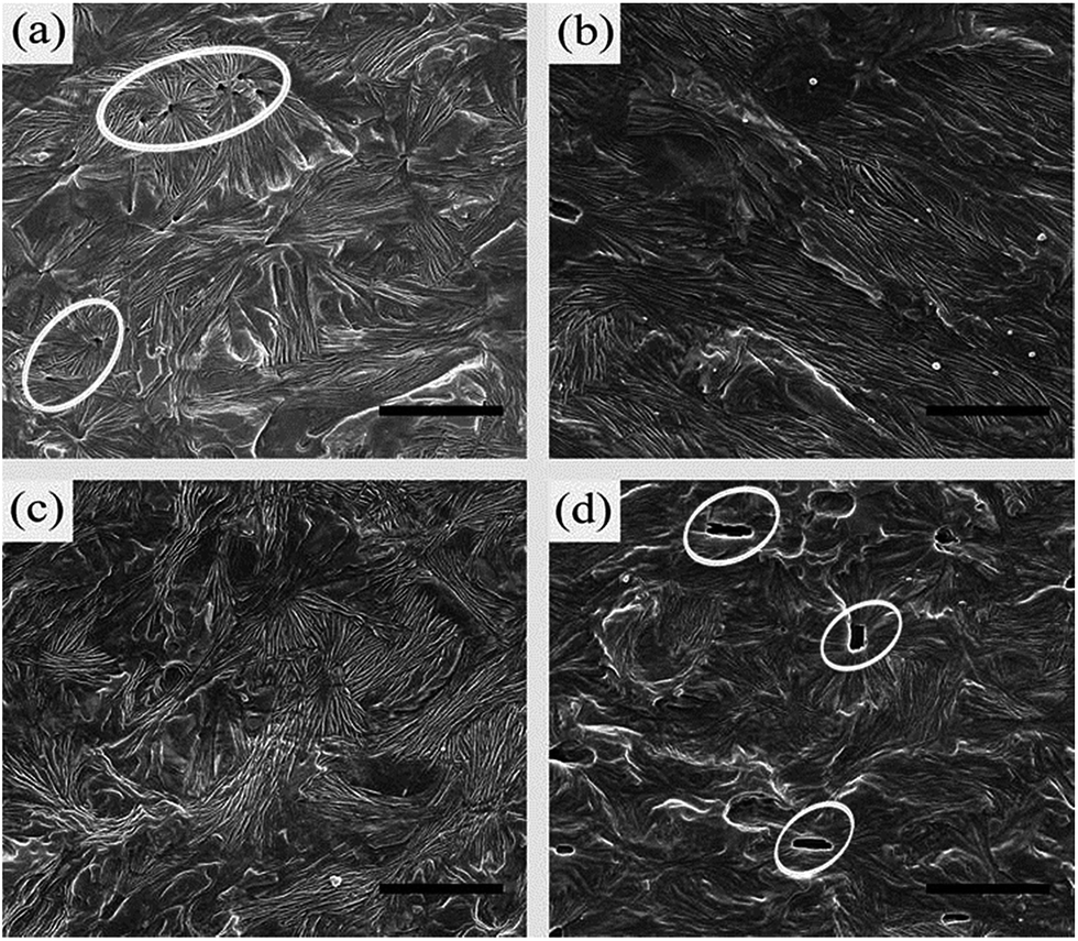 | ||
| Fig. 2 SEM images showing the typical supermolecular structures of (a) iPP/0.05TMB, (b) iPP/0.2TMB, (c) iPP/0.3TMB and (d) iPP/0.6TMB. Scale bars denote 3 μm. | ||
As listed in Table 1, both DSC and XRD measurements reveal that the four specimens containing different contents of β-phase nucleating agent and crystalline morphologies exhibit a similar content of β-phase. However, there is a great difference among the curves in the creep time scale. In Fig. 1, iPP/0.05TMB goes through the shortest time to reach the fatigue failure point whereas iPP/0.2TMB and iPP/0.3TMB experience similar and longer times; iPP/0.6TMB spends the longest time before fatigue failure. The difference in creep resistance is mainly due to the various crystalline morphologies, which are created by different contents of β-phase nucleating agent, as shown in Fig. 2. Besides that, in Table 1, iPP/0.2TMB and iPP/0.3TMB show similar long spacing, which are longer than iPP/0.05TMB and shorter than iPP/0.6TMB. The different long spacings listed in Table 1, which were calculated from the different curves of 1D scattering intensity SAXS distributions of various contents of β-iPP shown in Fig. 3, should be another factor for the different creep resistances.
| β-Phase nucleating agent | 0.05 | 0.2 | 0.3 | 0.6 |
|---|---|---|---|---|
| εc (%) | 11 | 11 | 11 | 11 |
| Kβ (%) | 87.1 | 86.4 | 85.6 | 87.5 |
| dac (nm) | 16 | 17 | 17 | 19 |
| Xcβ (%) | 22.7 | 25 | 23.4 | 24.6 |
 | ||
| Fig. 3 1D scattering intensity SAXS distributions at different contents of β-phase nucleating agent | ||
Crystalline structure evolution during creep deformation
The melting behaviors of beta-iPP specimens obtained at different strains are exhibited in Fig. 4. For iPP/0.05TMB, two main fusion peaks of undeformed samples are observed at around 151.5 and 164 °C, indicating the fusion of β-iPP and α-iPP, respectively.47 Before being stretched at complete fatigue failure point (strain ≈ 60%), the fusion peak of α-iPP seems stronger and stronger with the increasing strain, whereas the fusion peak of β-iPP, which reflects the content of β-iPP, reduces, so as to nearly disappear. This is also shown by the variation of crystallinity for the β-phase (Xcβ) with strain in Fig. 5. Xcβ gradually decreases from 22% to 5%. Meanwhile, the melting temperature of the β-phase (Tmβ) reaches lower and lower temperature. With the further increase of the strain (≥60%), the fusion peak of β-iPP becomes very weak, whereas the fusion of α-iPP predominates on the following heating process. It is believed that the increasingly smaller fusion peak of the β-phase during creep deformation reveals the β/α transformation in this experiment. Besides that, it is interesting to notice the change of Tmβ after being stretched. It maintains invariable in instantaneous deformation and primary creep region (strain ≤ 10%) and decreases gradually after the strain of fatigue failure (>10%). This means that, at low strain, instead of changing the lamellae structure of β-iPP, the applied stress mainly promotes the orientation and deformation of amorphous phases, which agrees with the result from Brown et al.37,38 However, at medium strain (10–60%), the applied stress induces the breakage and fragmentation of the lamellae, leading to the gradually reduced Tmβ values. Furthermore, at high strain (>60%), one should notice that the fusion of α-iPP becomes broader with increasing strain, which is different from the sharp fusion obtained in normal conditions. This can be attributed to the broadening of the d-spacing distribution by deformation of crystals.38 | ||
| Fig. 4 DSC melting curves of (a) iPP/0.05TMB, (b) iPP/0.2TMB, (c) iPP/0.3TMB and (d) iPP/0.6TMB samples obtained at different strains as indicated on the graphs. | ||
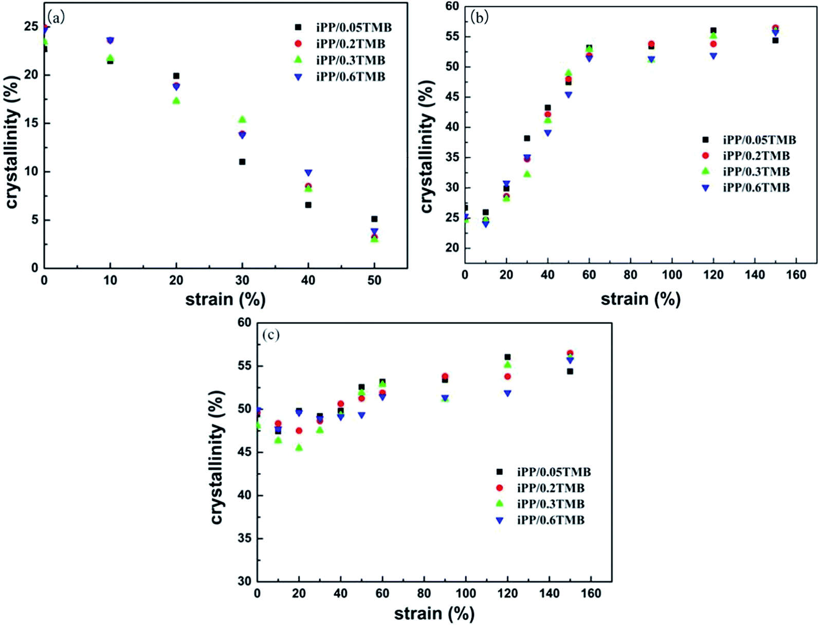 | ||
| Fig. 5 The variation of crystallinity of (a) β-phase, (b) α-phase and (c) β + α for samples of different nucleating contents with different strains. | ||
For other β-iPP with different content of β-phase nucleating agent, similar melting behaviors of specimens as a function of the strain are observed: the β-phase predominates at low strain whereas α-iPP predominates at high strain, suggesting the process of β/α transformation during creep deformation. However, it is noticed that the intensity of the fusion peak of β-iPP is almost invariant at the beginning, suggesting that the content of β-iPP does not change at low strain (≤10%). This can be further shown by the variation of Xcβ as shown in Fig. 5. Xcβ shows similar variation trends in iPP/0.05TMB, iPP/0.2TMB, iPP/0.3TMB and iPP/0.6TMB. The content of the β-phase tends to decrease monotonically to zero with increasing strain. However for the α-phase, Xcα tends to decrease first due to the breakup under stress and then increase with the increasing strain, and finally achieving a platform. This means that the different crystalline morphologies of β-iPP have similar crystalline structure evolution during creep deformation.
Fig. 5 shows the variation of crystallinity with strain. For β-iPP, Xcβ decreases gradually whereas Xcα increases with increasing strain, indicating the β/α transformation. Furthermore, Xc would slightly decrease at low strain and then increase slightly with the development of deformation. The slight decrease of Xc proves that the loss on the process of β–α transformation and the fragmentation of lamellar structure under stress. Obviously, the slight increase of Xc in the following creep behavior is mainly attributed to the stress-induced crystallization.
Although the evolution of crystalline structure during deformation has been shown by DSC measurement, one should find that the β/α transformation on the melting process would be in error to some extent in analyzing the DSC data. The β/α transformation would result in higher value of α-iPP crystallinity and relatively lower value of β-iPP crystallinity, especially at the beginning of the measurement. Therefore, to further prove the crystalline evolution from DSC measurement, the variation of crystalline structure during creep were also investigated by XRD measurement, which are shown in Fig. 6 and 7.
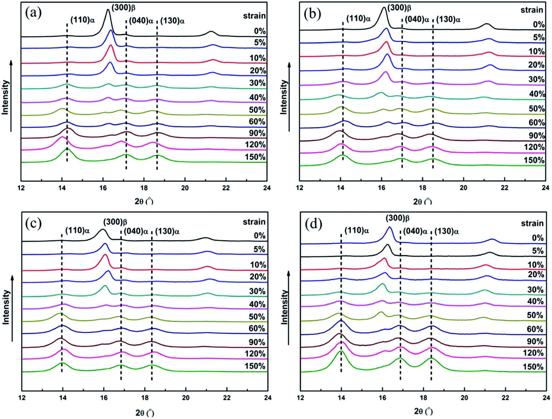 | ||
| Fig. 6 XRD patterns of (a) iPP/0.05TMB, (b) iPP/0.2TMB, (c) iPP/0.3TMB and (d) iPP/0.6TMB samples obtained at different strains as indicated on the graph. | ||
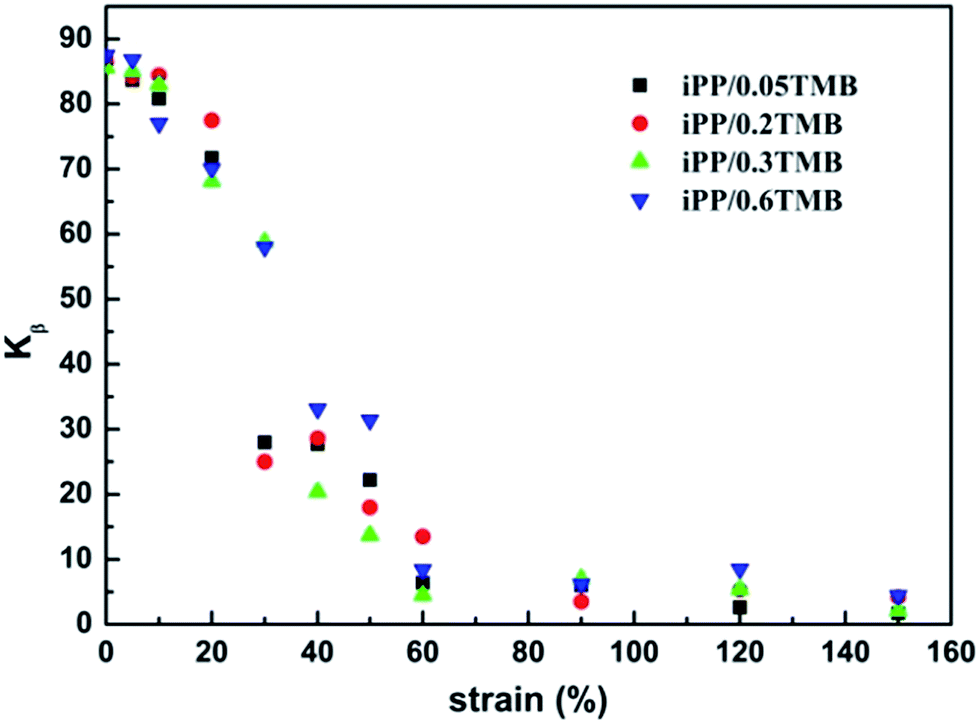 | ||
| Fig. 7 Variation of the relative crystallinity of the β-phase as the function of strain. | ||
From Fig. 6 one can see that, the XRD profiles exhibit typical characteristic diffraction peaks at 2θ = 16.2 and 21.2°, arising from the (300) and (301) planes of β-iPP, respectively. Besides that, the characteristic diffraction peaks of the α-iPP can be differentiated at 2θ = 14.3 (110), 17.1 (040) and 18.7 (130). According to the results of XRD shown in Table 1, the relative contents of β-iPP in iPP/0.05TMB, iPP/0.2TMB iPP/0.3TMB and iPP/0.6TMB samples are calculated as 87.1, 86.4, 85.6 and 87.5%, respectively, indicating that the samples with different contents of β-phase nucleating agent have a similar content of β-phase. Furthermore, in Fig. 7, all the samples show a similar variation trend in the relative content of β-phase after being creep-deformed. In other words, the content of β-phase reduces gradually with the increasing strain, which is consistent with the result of DSC measurement. At first, when the strain is smaller than 10%, the intensity of Kβ-XRD is little changed. This is the same result as found in DSC measurement. One should note that the platform of β-iPP diffractions at the start of creep (instantaneous deformation region) is mainly ascribed to the stretching between adjacent lamella leading to orientation in the amorphous regions. Afterwards, there is a greatly reduced intensity of Kβ-XRD when the strain increases to higher than 10% with a gradual increase of α-iPP content and decrease of β-iPP content with strain, indicating the process of melting–recrystallization. After a sharp decline, the Kβ-XRD of β-iPP reaches towards zero at strain around 60% and the intensity of β-iPP also nearly disappears in all the samples, as shown in Fig. 6.
Fig. 8 shows the variation of the full width at half maximum (FWHM) of 110-reflections as a function of strain. At small strain (≤10%), the crystallites are considered to become substantially disordered as reflected by the increasing FWHM data. This can be ascribed to the deformation in the lamellar structure caused by the stretching. At medium strain between 10 and 60%, the crystallites are considered to have higher structural order with less disordered structure due to the melting–recrystallization process. Finally, after the strain of 60%, the value of FWHM stays invariant indicating the maintenance of crystalline structure. At this stage, the disentanglement of amorphous molecular chains represents the main deformation.
 | ||
| Fig. 8 Variation of the full width at half maximum of 110-reflections as a function of strain. | ||
Crystalline morphology change during deformation
Fig. 9 exhibits the microstructures of β-iPP obtained at different strains. Before creep, specimens with different contents of β-phase nucleating agent show different supermolecular structures, which are consistent with the previous study, namely well-developed β-spherulites, bundle-like lamellar clusters and needle-like nucleating structure. At a low strain of 10%, the samples begin to show clear crazes which explain the stress whitening during deformation. The typical crazes produced during creep are shown in Fig. 10. Crazes are cracks that remain bridged by fibrils of polymer and are perpendicular to the deformation direction,48–50 as illustrated in Fig. 9 and 10. It is acknowledged that crazes are a sort of main localized plastic deformation mechanism in semicrystalline polymers.51 Recently, Castagnet et al. characterized PVDF by volumetric measurements during tensile test by SAXS.52 They have shown that cavities would be generated in the amorphous phase between lamella just before yielding. In our study, at low strain (10%), crazes are exhibited on all samples, showing the direction perpendicular to the stress. Besides that, according to the results of DSC and XRD, the crystalline transformation only occurs to a small degree under low strain (10%). Furthermore, the whole crystallization is little changed at this stage. Thus it is believed that this level of strain (10%) is too small to induce the process of melting–recrystallization. This is possibly due to the fact that in the instantaneous deformation region, specimens suffer elastic stretching between adjacent lamella. Then in the primary creep and second creep regions, samples suffer the plastic deformation of crystallization. Namely, at small strains, the crystal mainly undergoes elastic and viscoelastic stretching to drive the orientation of the interlamellar amorphous phase. | ||
| Fig. 9 SEM photographs of the microstructures in iPP/0.05TMB, iPP/0.2TMB, iPP/0.3TMB and iPP/0.6TMB samples at different final strains: ε = 10%, ε = 30%, ε = 50% and ε = 150%. The tensile direction is vertical as shown on the right. Scale bar = 10 μm. | ||
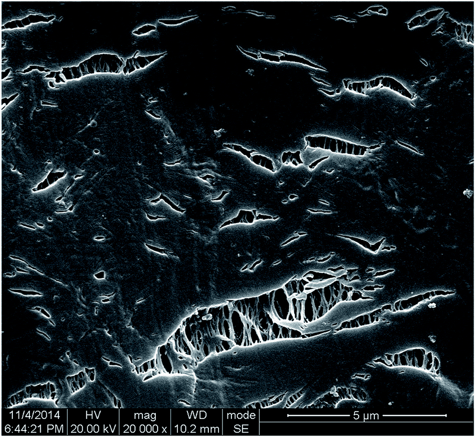 | ||
| Fig. 10 SEM photographs of the microstructures in iPP/0.05TMB at strain of 10%. The tensile direction is vertical. | ||
At a strain of 30%, the specimens suffer an accelerating strain speed process. The crystalline transformation and the tensile deformation make the crystalline morphology irregular. The crystalline morphologies become disordered for all β-iPP samples. For the iPP/0.05TMB sample, the well-developed β-spherulites change and tend to break into fragments. Furthermore, some large slits can be seen which cross the whole spherulites and the boundaries. For the iPP/0.2TMB specimen, the bundle-like morphology becomes inconspicuous and some large slits are further stretched along the stress direction, leading to the direction of the crazes transforming to the tensile direction gradually; additionally, initial fiber-like structures occur in this stage. Hence, a strain of 30% induces a substantial change of the crystalline morphology in the iPP/0.2TMB specimen. Compared to the obvious tensile deformation of crazes and crystallization in iPP/0.05TMB and iPP/0.2TMB, the microstructures show little change in iPP/0.3TMB and iPP/0.6TMB specimens. It can be deduced to that the higher contents of β-phase nucleating agent would prevent the further growth of crazes. On the other hand, iPP/0.2TMB and iPP/0.3TMB have a similar level of creep resistance, which means that the growth of crazes do not affect the creep resistance of samples.
At a strain of 50%, both iPP/0.05TMB and iPP/0.2TMB exhibit more serious defects. For the iPP/0.05TMB specimen, the well-developed β-spherulites are no longer observed. Contrarily, a large number of slits can be seen due to the fragmentation and separation of the crystallization structure, and the slits start to orient at this strain. It was observed that cavities firstly grow perpendicular to the applied stress and then elongate in the direction of the stress.53 For the iPP/0.2TMB specimen, the size of oriented slits is much smaller than that observed at the strain of 30%. This is possibly due to the decrease of cross section, leading to the shrinkage of apertures in the fiber-like structure. As for the iPP/0.3TMB and iPP/0.6TMB specimens, there are larger crazes and slightly oriented fragmentation, as shown in the SEM pictures. However, the orientation in these specimens is still unclear.
With further increasing of the strain (150%), all iPP/0.05TMB, iPP/0.2TMB, iPP/0.3TMB and iPP/0.6TMB samples exhibit highly oriented structure. The fiber-like structure is deduced to be of oriented crystals, namely newly formed α-phase, which has relatively smooth surface features. Obviously, the entanglement of molecular chain most likely contributes to accelerating fracture observed at the last stage of creep deformation after creep fatigue failure point.
PALS results
The fourth component obtained from the results of PALS, attributed to pick-off annihilation of o-Ps formed in the free-volume local holes, depends on the dimensions of free volume local holes where the positrons can be localized forming a Ps state.54,55 The fourth lifetime, τ4, and the relative intensity, I4, are given in Fig. 11. τ4 positively associates with the free volume radius (R). τ4 can be calculated by a semiempirical equation:
 | (4) |
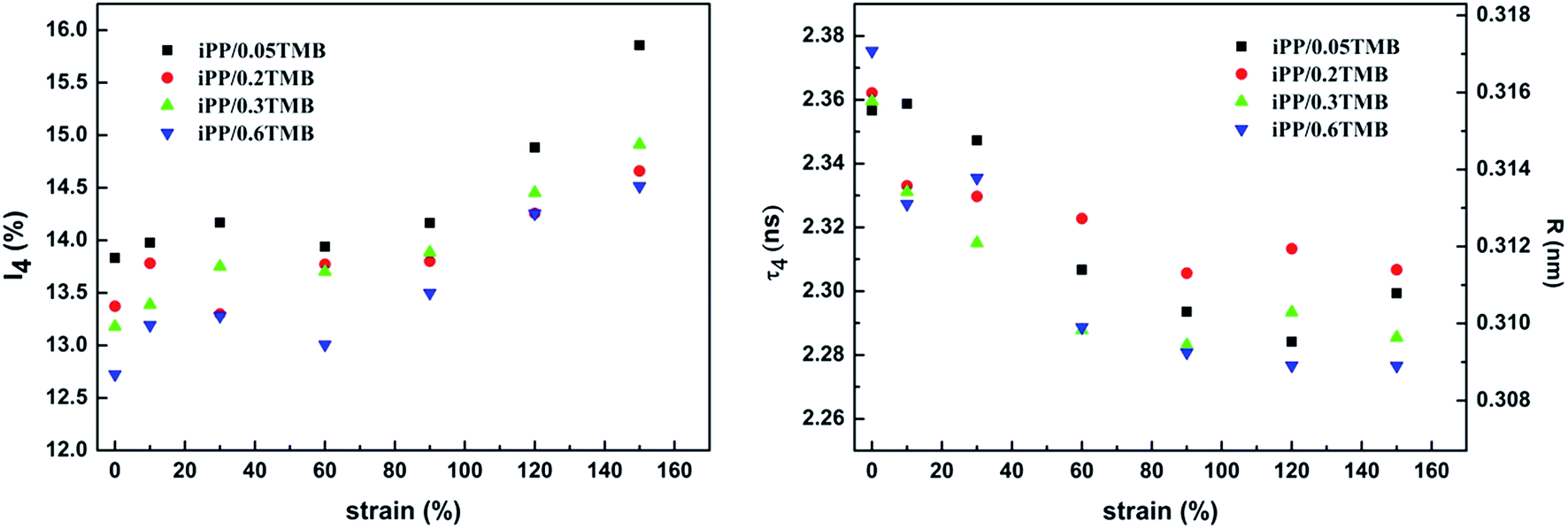 | ||
| Fig. 11 Lifetime (τ4) and intensity (I4) of the fourth component as the function of strain for β-iPP during creep. | ||
For all types of β-iPP having different contents of nucleating agent, the fourth component has similar variation. At small strain (≤10%), τ4 decreases and I4, reflecting the Ps formation probability in the free volume holes, increases. This might be due to the breakup of the free volume during deformation showing as an increase in size while decrease in number for the free volume. At medium strain (10–60%), τ4 goes down fast but I4 increases slightly exhibiting a similar variation trend of free volume in pure iPP.39 Because of polymer chains with larger free volume having higher mobility, it would be easier to orient and rearrange such chains when the melt–recrystallization process occurs, which generates the decrease of τ4. At high strain (≥60%), τ4 slightly reduces and I4 greatly increases. This can be attributed to that the further deformation of the chains with more defects generated in the amorphous region results in the increasing of the number of free volume holes. The variation of τ4 and I4 on different stages reflects the change of free volume, which would provide a view for the evolution of amorphous regions during creep deformation.
Conclusions
In summary, crystalline transformation has been observed by DSC and XRD measurements during the creep deformation. Besides, the change of crazes and the generation of fiber-like structures during deformation are observed by SEM measurement. It is interesting to observe that a higher content of β-phase nucleating agent hinders the growth of crazes. Furthermore, the changes of free volume during deformation have been explored by PALS, showing the microscopic changes of amorphous regions. For the iPP/0.05TMB specimen, the well-developed β-spherulites achieved by critical content of β-phase nucleating agent show lowest creep resistance compared with other specimens. For iPP/0.2TMB and iPP/0.3TMB samples with bundle-like morphology, they have higher creep-resistant ability than iPP/0.05TMB specimen and lower than iPP/0.6TMB specimen with needle-like nucleation structure achieved by supercritical content of β-phase nucleating agent. During creep behavior, the lamella of all β-iPP exhibit elastic/plastic deformation at the beginning of creep (strain ≤ 10%), just before the point of fatigue failure, which can be deduced to the movement in amorphous regions. Subsequently, at the strain between 11 and 60%, a crystalline transformation phenomenon appears after the point of creep fatigue failure (strain = 11%). The results of DSC and XRD show that samples with different contents of β-phase nucleating agent have the same variation trend in crystalline transformation. Besides that, SEM measurement shows that a higher content of β-phase nucleating agent would restrain the growth of the cavities, but have no direct effect on the creep resistance. It is deduced that the crystal morphology with different long spacings is the main factor in determining the creep resistance. Finally, after the strain of 60%, stretched-induced oriented crystals become evident.Acknowledgements
This project is supported by the National Natural Science Foundation of China (No. 51133005 and 51421061), and the Research Fund for the Doctoral Program of Higher Education (No. 20120181130013).References
- C. Grein, C. J. G. Plummer, H. H. Kausch, Y. Germain and Ph. Béguelin, Influence of β nucleation on the mechanical properties of isotactic polypropylene and rubber modified isotactic polypropylene, Polymer, 2002, 43(11), 3279–3293 CrossRef CAS.
- C. Grein, Toughness of neat, rubber modified and filled β-nucleated polypropylene: from fundamentals to applications//Intrinsic Molecular Mobility and Toughness of Polymers II, Springer, Berlin, Heidelberg, 2005, pp. 43–104 Search PubMed.
- J. Varga, β-Modification of isotactic polypropylene: preparation, structure, processing, properties, and application, J. Macromol. Sci., Part B: Phys., 2002, 41(4–6), 1121–1171 CrossRef.
- J. Varga, Supermolecular structure of isotactic polypropylene, J. Mater. Sci., 1992, 27(10), 2557–2579 CrossRef CAS.
- B. Lotz, J. C. Wittmann and A. J. Lovinger, Structure and morphology of poly(propylenes): a molecular analysis, Polymer, 1996, 37(22), 4979–4992 CrossRef CAS.
- B. Lotz, S. Graff, C. Straupe and J. C. Wittmann, Single crystals of γ phase isotactic polypropylene: combined diffraction and morphological support for a structure with non-parallel chains, Polymer, 1991, 32(16), 2902–2910 CrossRef CAS.
- J. Varga and J. Karger-Kocsis, The occurrence of transcrystallization or row-nucleated cylindritic crystallization as a result of shearing in a glass-fiber-reinforced polypropylene, Compos. Sci. Technol., 1993, 48(1), 191–198 CrossRef CAS.
- J. Varga and J. Karger-Kocsis, Rules of supermolecular structure formation in sheared isotactic polypropylene melts, J. Polym. Sci., Part B: Polym. Phys., 1996, 34(4), 657–670 CrossRef CAS.
- H. J. Leugerin and G. Kirsch, Effect of crystallization from oriented melts on crystal-structure of isotactic polypropylene, Angew. Makromol. Chem., 1973, 33, 17–23 CrossRef.
- R. H. Somani, B. S. Hsiao, A. Nogales, H. Fruitwala, S. Srinivas and A. H. Tsou, Structure development during shear flow induced crystallization of i-PP: in situ wide-angle X-ray diffraction study, Macromolecules, 2001, 34(17), 5902–5909 CrossRef CAS.
- H. Huo, S. Jiang, L. An and J. Feng, Influence of shear on crystallization behavior of the β phase in isotactic polypropylene with β-nucleating agent, Macromolecules, 2004, 37(7), 2478–2483 CrossRef CAS.
- J. M. Crissman, Mechanical relaxation in polypropylene as a function of polymorphism and degree of lamella orientation, J. Polym. Sci., Part A-2, 1969, 7(2), 389–404 CrossRef CAS.
- Y. Fujiwara, Das doppelschmelzverhalten der β-Phase des isotaktischen polypropylens, Colloid Polym. Sci., 1975, 253(4), 273–282 CAS.
- J. Varga, β-Modification of isotactic polypropylene: preparation, structure, processing, properties, and application, J. Macromol. Sci., Part B: Phys., 2002, 41(4–6), 1121–1171 CrossRef.
- J. Varga and A. Menyhard, Effect of solubility and nucleating duality of N,N′-dicyclohexyl-2,6-naphthalenedicarboxamide on the supermolecular structure of isotactic polypropylene, Macromolecules, 2007, 40(7), 2422–2431 CrossRef CAS.
- R. J. Varley, M. Dell’Olio, Q. Yuan, S. Khor, K. H. Leong and S. Bateman, Different β nucleants and the resultant microstructural, fracture, and tensile properties for filled and unfilled ISO polypropylene, J. Appl. Polym. Sci., 2013, 128(1), 619–627 CrossRef CAS.
- S. C. Tjong, J. S. Shen and R. K. Y. Li, Mechanical behavior of injection molded β-crystalline phase polypropylene, Polym. Eng. Sci., 1996, 36(1), 100–105 CAS.
- P. Tordjeman, C. Robert, G. Marin and P. Gerard, The effect of α, β crystalline structure on the mechanical properties of polypropylene, Eur. Phys. J. E: Soft Matter Biol. Phys., 2001, 4(4), 459–465 CrossRef CAS.
- C. Grein, Toughness of neat, rubber modified and filled β-nucleated polypropylene: from fundamentals to applications//Intrinsic Molecular Mobility and Toughness of Polymers II, Springer, Berlin, Heidelberg, 2005, pp. 43–104 Search PubMed.
- T. Wu, M. Xiang, Y. Cao, J. Kang and F. Yang, Influence of lamellar structure on the stress–strain behavior of β nucleated polypropylene under tensile loading at elevated temperatures, RSC Adv., 2015, 5(54), 43496–43507 RSC.
- H. Münstedt, Rheological experiments at constant stress as efficient method to characterize polymeric materials, J. Rheol., 2014, 58(3), 565–587 CrossRef.
- C. Lin, J. Liu, F. Gong, G. Zeng, Z. Huang, L. Pan, J. Zhang and S. Liu, High-temperature creep properties of TATB-based polymer bonded explosives filled with multi-walled carbon nanotubes, RSC Adv., 2015, 5(27), 21376–21383 RSC.
- A. F. Osman, Y. Andriani, G. A. Edwards, T. L. Schiller, K. S. Jack, I. C. Morrow, P. J. Haller and D. J. Martin, Engineered nanofillers: impact on the morphology and properties of biomedical thermoplastic polyurethane nanocomposites, RSC Adv., 2012, 2(24), 9151–9164 RSC.
- A. S. Alavijeh, R. M. H. Khorasany, A. Habisch, G. G. Wang and E. Kjeang, Creep properties of catalyst coated membranes for polymer electrolyte fuel cells, J. Power Sources, 2015, 285, 16–28 CrossRef.
- ASTM D 2990-01, Standard test methods for tensile, compressive, and flexural creep and creep-rupture of plastics, ASTM International, West Conshohocken, 2001 Search PubMed.
- A. D. Drozdov and A. L. H. Lejre, Viscoelasticity, viscoplasticity, and creep failure of polypropylene/clay nanocomposites, Compos. Sci. Technol., 2009, 69(15), 2596–2603 CrossRef CAS.
- A. D. Drozdov, Creep failure of polypropylene: experiments and constitutive modeling, Int. J. Fract., 2009, 159(1), 63–79 CrossRef CAS.
- A. D. Drozdov, Creep rupture and viscoelastoplasticity of polypropylene, Eng. Fract. Mech., 2010, 77(12), 2277–2293 CrossRef.
- H. N. Lee, R. A. Riggleman, J. J. de Pablo and M. D. Ediger, Deformation-induced mobility in polymer glasses during multistep creep experiments and simulations, Macromolecules, 2009, 42(12), 4328–4336 CrossRef CAS.
- L. M. Vas and P. Bakonyi, Estimating the creep strain to failure of PP at different load levels based on short term tests and Weibull characterization, eXPRESS Polym. Lett., 2012, 6(12), 987–996 CrossRef CAS.
- A. Peterlin, Molecular model of drawing polyethylene and polypropylene, J. Mater. Sci., 1971, 6(6), 490–508 CrossRef CAS.
- A. Peterlin, Plastic deformation of polymers with fibrous structure, Colloid Polym. Sci., 1975, 253(10), 809–823 CAS.
- Z. Jiang, Y. Tang, Y. Men, H. F. Enderle, D. Lilge, S. V. Roth, R. Gehrke and J. Rieger, Structural evolution of tensile-deformed high-density polyethylene during annealing: scanning synchrotron small-angle X-ray scattering study, Macromolecules, 2007, 40(20), 7263–7269 CrossRef CAS.
- Z. Jiang, Y. Tang, J. Rieger, H. F. Enderle, D. Lilge, S. V. Roth, R. Gehrke, W. Heckmann and Y. Men, Two lamellar to fibrillar transitions in the tensile deformation of high-density polyethylene, Macromolecules, 2010, 43(10), 4727–4732 CrossRef CAS.
- M. A. Monge, J. A. Diaz and R. Pareja, Strain-induced changes of free volume measured by positron lifetime spectroscopy in ultrahigh molecular weight polyethylene, Macromolecules, 2004, 37(19), 7223–7230 CrossRef CAS.
- K. M. Cheng, C. Tian, Y. Du, F. He, J. H. Wang and J. Sun, Effect of OPS Dispersion Method on the Free Volume of Polyurethane by Positron Annihilation Lifetime Spectroscopy (PALS), Polym.-Plast. Technol. Eng., 2012, 51(4), 396–400 CrossRef CAS.
- E. N. Brown, D. M. Dattelbaum, D. W. Brown, P. J. Rae and B. Clausen, A new strain path to inducing phase transitions in semi-crystalline polymers, Polymer, 2007, 48(9), 2531–2536 CrossRef CAS.
- E. N. Brown, B. Clausen and D. W. Brown, In situ measurement of crystalline lattice strains in phase IV polytetrafluoroethylene, J. Neutron Res., 2007, 15(2), 139–146 CrossRef.
- C. Jia, Q. Zhang, X. Liao, J. Jun, L. Wu, K. Ni, Q. Yang, Z. An and G. Li, Hierarchical microstructure changes and the molecular mechanism of polypropylene under a critical failure strain during creep, Polymer, 2015, 67, 92–100 CrossRef CAS.
- G. R. Strobl and M. Schneider, Direct evaluation of the electron density correlation function of partially crystalline polymers, J. Polym. Sci., Polym. Phys. Ed., 1980, 18(6), 1343–1359 CrossRef CAS.
- J. X. Li, W. L. Cheng and D. Jia, A study on the heat of fusion of β-polypropylene, Polymer, 1999, 40(5), 1219–1222 CrossRef CAS.
- M. Liu, B. Guo, M. Du, F. Chen and D. Jia, Halloysite nanotubes as a novel β-nucleating agent for isotactic polypropylene, Polymer, 2009, 50(13), 3022–3030 CrossRef CAS.
- A. T. Jones, J. M. Aizlewood and D. R. Beckett, Crystalline forms of isotactic polypropylene, Makromol. Chem., 1964, 75, 134–158 CrossRef.
- M. Dong, Z. Guo, Z. Su and J. Yu, Study of the crystallization behaviors of isotactic polypropylene with sodium benzoate as a specific versatile nucleating agent, J. Polym. Sci., Part B: Polym. Phys., 2008, 46(12), 1183–1192 CrossRef CAS.
- M. Dong, Z. Guo, J. Yu and Z. Su, Crystallization behavior and morphological development of isotactic polypropylene with an aryl amide derivative as β-form nucleating agent, J. Polym. Sci., Part B: Polym. Phys., 2008, 46(16), 1725–1733 CrossRef CAS.
- M. Dong, Z. X. Guo, J. Yu and Z. Su, Study of the assembled morphology of aryl amide derivative and its influence on the nonisothermal crystallizations of isotactic polypropylene, J. Polym. Sci., Part B: Polym. Phys., 2009, 47(3), 314–325 CrossRef CAS.
- A. Menyhárd and J. Varga, The effect of compatibilizers on the crystallisation, melting and polymorphic composition of β-nucleated isotactic polypropylene and polyamide 6 blends, Eur. Polym. J., 2006, 42(12), 3257–3268 CrossRef.
- K. Friedrich, Crazes and shear bands in semi-crystalline thermoplastics, Adv. Polym. Sci., 1983, 225–274 CrossRef CAS.
- H. H. Kausch, R. Gensler, C. Grein, C. J. G. Plummer and P. Scaramuzzino, Crazing in semicrystalline thermoplastics, J. Macromol. Sci., Phys., 1999, 38(5–6), 803–815 CrossRef.
- I. Narisawa and M. Ishikawa, Crazing in semicrystalline thermoplastics//Crazing in Polymers, Springer, Berlin Heidelberg, 1990, vol. 2, pp. 353–391 Search PubMed.
- P. B. Bowden and R. J. Young, Deformation mechanisms in crystalline polymers, J. Mater. Sci., 1974, 9(12), 2034–2051 CrossRef CAS.
- S. Castagnet, S. Girault, J. L. Gacougnolle and P. Dang, Cavitation in strained polyvinylidene fluoride: mechanical and X-ray experimental studies, Polymer, 2000, 41(20), 7523–7530 CrossRef CAS.
- L. Laiarinandrasana, T. F. Morgeneyer, H. Proudhon, F. N'guyen and E. Maire, Effect of multiaxial stress state on morphology and spatial distribution of voids in deformed semicrystalline polymer assessed by X-ray tomography, Macromolecules, 2012, 45(11), 4658–4668 CrossRef CAS.
- P. Kirkegaard, N. J. Pedersen and M. M. Eldrup, PATFIT-88: a data-processing system for positron annihilation spectra on mainframe and personal computers, 1989 Search PubMed.
- O. E. Mogensen, Positron annihilation in chemistry, Berlin, Springer-Verlag, 1995 Search PubMed.
- H. Nakanishi, S. J. Wang, Y. C. Jean and S. C. Sharma, Positron annihilation studies of fluids, World Science, Singapore, 1988, p. 292 Search PubMed.
| This journal is © The Royal Society of Chemistry 2016 |