DOI:
10.1039/D2SM00068G
(Paper)
Soft Matter, 2022,
18, 2992-3003
Strain-stiffening seal
Received
13th January 2022
, Accepted 17th March 2022
First published on 30th March 2022
Abstract
An elastomeric seal needs to be soft to accommodate installation but stiff to block fluid flow. Here we show that the two requirements are better fulfilled by a strain-stiffening elastomer than a neo-Hookean elastomer. We represent the strain-stiffening elastomer using the Gent model, and calculate the deformation in the elastomeric seal using an approach analogous to the lubrication theory of a viscous fluid between rigid walls. We determine the sealing pressure on the basis of two modes of leak. The seal leaks by elastic deformation when the fluid pressure exceeds the contact pressure between the seal and the rigid wall. The seal leaks by rupture when the energy release rate of a crack exceeds the toughness of the elastomer. For both modes of leak, a strain-stiffening elastomer enhances the sealing pressure compared to a neo-Hookean elastomer. We construct diagrams in which the two modes of leak are demarcated. It is hoped that this study will aid in the development of materials and geometries of seals.
1. Introduction
Elastomers are commonly used to make seals in everyday applications, such as O-rings for plumbing, engines, drinking bottles, and pressure cookers. Elastomeric seals are also used in oilfields to isolate fluids in gaps between pipes and boreholes,1,2 in deep ocean robots to stop the injection of water into the chamber under the 102 to 103 atmosphere pressure,3 and in shock absorbers of landing gears to prevent leaking of pressurized oil,4 In many such applications, seals are required to sustain fluid pressure much higher than the modulus of the elastomer.
The biological analogy of sealing is not seldom. For example, when a red blood cell (RBC) passes through capillaries,5 the RBC deforms elastically, and the fluid might leak through the flaws between the cell and the vessel. Meanwhile, the easiness of a cell passing a microfluidic channel is used as a method to diagnose the cancer cell, which is stiffer than a healthy cell.6 When blood vessels are clogged by RBC-rich or fibrin-rich thrombus, the occasion is similar to a seal blocking the channel. Fibrils, such as collagens, show uniaxial elastic strains of less than 30%.7 In these phenomena, cells and biopolymers could be conceptually regarded as elastomer seals at microscales.
The softness of the elastomers is needed for the operation of a seal, but may also cause the seal to leak.8 Consider a seal compressed between two rigid walls and subject to a fluid pressure (Fig. 1a). The seal should be soft enough to fill gaps between hard materials and roughness on surfaces. Furthermore, the softness of elastomers enables the seals to be installed at a low cost. Subject to a pressure gradient, a seal may leak by elastic deformation or by rupture.9–13 Consequently, a seal must be stiff enough to withstand high fluid pressure.
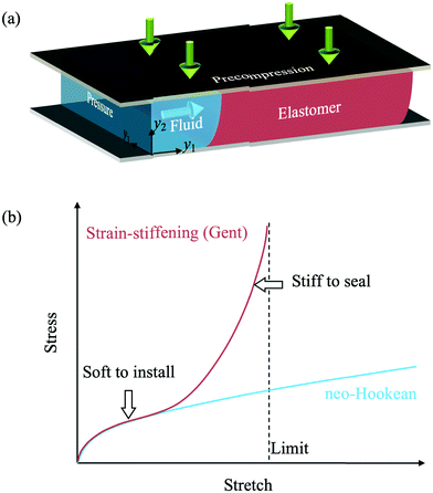 |
| | Fig. 1 Elastomeric seals. (a) An elastomer is precompressed between two rigid walls and is subject to fluid pressure. (b) Stress–stretch curves of a neo-Hookean material and a strain-stiffening material. | |
To accommodate both requirements of softness and stiffness, one may make a seal stiffen steeply with deformation (Fig. 1b). The seal is soft at small deformation to fill the gap between hard materials but is stiff at large deformation to bear fluid pressure. Such strain-stiffening behavior is commonly observed in elastomers and used for designs of many applications.14–18 An elastomer consists of a three-dimensional network of polymeric chains. Under no external force, a chain coils to maximize entropy. Subject to an external force, the chain uncoils and stiffens as it approaches its contour length.19,20 One can also design a composite elastomer to tune independently the softness at small deformation and the level of deformation at which the elastomer stiffens steeply.21–23
Wang et al. analyzed a seal without strain stiffening effect with a neo-Hookean material model.13 Here we study how strain-stiffening improves sealing capacity. We predict sealing pressures for two representative modes of leak, by elastic deformation and by rupture. For both mopeds of leak, we show that the sealing pressure of a strain-stiffening seal is increased compared to a neo-Hookean seal. The sealing pressure is amplified by either reducing the limiting strain or increasing the precompression. We also demarcated the two modes of leak on planes of various material parameters.
2. Deformation of strain-stiffening seal
2.1 Nonlinear elastic theory
Following Wang et al.,13 this subsection formulates a model without specifying any stress–strain model. The model is analogous to the lubrication theory of viscous fluid between two rigid walls. Consider a block of elastomer with the dimensions of L × H × B in the reference state (Fig. 2a). The material is incompressible and deforms under the plane strain conditions. The elastomer is homogeneously precompressed by the two rigid walls to height h and length l (Fig. 2b). Under the plane strain conditions, incompressibility implies that HL = hl. The ratio λ = h/H = L/l is a dimensionless measure of the precompression. After the precompression, the elastomer is taken to be bonded to the bottom wall. Subject to a fluid pressure p, the elastomer deforms (Fig. 2c).
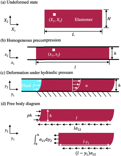 |
| | Fig. 2 The cross-section of a seal under the plane strain conditions. (a) In the undeformed state, a material particle is labeled by coordinates (X1, X2). (b) After being uniformly precompressed in the X2 direction, the elastomer is bonded to the bottom wall. The top wall is frictionless. In the precompressed state, the material particle is labeled by coordinates (x1, x2). (c) When a fluid pressure p is applied at one end, the material particle moves to a place of coordinates (y1, y2). The displacement is recorded by u(x2). (d) The free body diagram of the seal. | |
A material particle, of the coordinates (X1, X2) in the undeformed state, moves to a place of coordinates (x1, x2) in the homogeneously precompressed state, and to a place of coordinates (y1, y2) in a state under the fluid pressure. Note that x1 = λ−1X1 and x2 = λX2. By an analogy to the lubrication theory, we seek a field of elastic deformation of the form (Fig. 2c):
| |  | (1) |
Here
u(
x2) is the horizontal displacement field of material particles due to the fluid pressure.
Eqn (1) could be rewritten as the function of (
X1,
X2):
| |  | (2) |
These equations specify a field of deformation
yi(
X). Recall that the deformation gradient is
FiK = ∂
yi/∂
XK, so that
| | 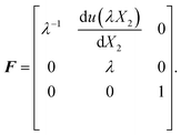 | (3) |
It is convenient to use (
y1,
y2) as independent variables:
| | 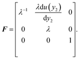 | (4) |
The incompressibility of the elastomer is confirmed by det(F) = 1. Let the in-plane components of the true stress be σ11, σ22, and σ12. For an incompressible elastic material, σ11–σ22 and σ12 are functions of the deformation gradient. Since the deformation gradient only varies with y2, we have
| |  | (5) |
Integrating the equilibrium equations,  and
and  , we find that the field of stress takes the following form
| |  | (6) |
where the integral constants
a,
b, and
c are determined by boundary conditions.
To simplify this boundary value problem, we assume that the top surface of the elastomer can slide relative to the top wall without friction. (The effect of frictional sliding will be discussed in Section 6.) We also ignore the edge effect by supposing that the aspect ratio L/H is large enough. Consider the free-body diagram for the entire elastomer (Fig. 2d). The fluid pressure exerts a horizontal net force hp on the left side of the elastomer. Since the top surface is frictionless, the horizontal force hp balances the shear force l × σ12(y2 = 0) at the bottom. Thus, we obtain b = hp/l. Associated with the frictionless top surface of elastomer, σ12(y2 = h) = 0, the value of a is determined as a = −p/l = −λp/L. To determine c, cut the elastomer vertically at any position y1, and use the right side for a free-body diagram (Fig. 2d). Eqn (6) results in a horizontal normal force  , and a horizontal shear force (l − y1)b, where the bottom surface does not slide, u(y2 = 0) = 0. The balance of the forces acting on the seal in the horizontal direction gives that
  . So far, we can write the field of stress as
| | 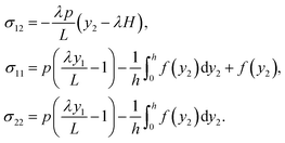 | (7) |
This distribution is applicable for any incompressible elastic material.
2.2. Strain-stiffening seals
We adopt the form of the strain energy density proposed by Gent to capture the strain-stiffening behavior of elastomers:| |  | (8) |
where μ is the shear modulus and Jlim measures the limit deformation.16 According to the deformation gradient in eqn (4), we write| |  | (9) |
For an incompressible elastic material, the true stress relates to the deformation gradient in the form of| |  | (10) |
A direct calculation gives that| | 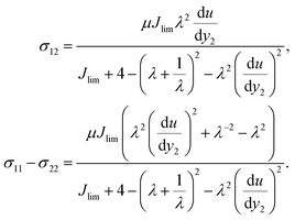 | (11) |
A combination of eqn (7) and (11) gives:| |  | (12) |
Drop the non-physical solution (du/dy2 < 0), we obtain| |  | (13) |
This first-order ordinary differential equation is solved under the boundary condition u = 0 at y2 = 0. To simplify the eqn (13), let û = u/H, ŷ2 = y2/H, and ![[p with combining circumflex]](https://www.rsc.org/images/entities/i_char_0070_0302.gif) = pH/μL. The analytical solution of û is
= pH/μL. The analytical solution of û is| | 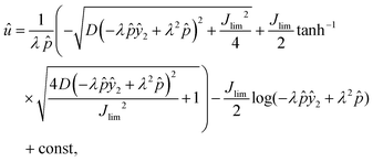 | (14) |
where| | 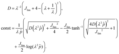 | (15) |
An integration of the displacement profile gives the volume of extrusion:| |  | (16) |
or| |  | (17) |
2.3. Neo-Hookean material
When both the applied precompression and the fluid pressure are small compared to those at the state of limiting stretch, the Gent model reduces to the neo-Hookean model. We summarize the results for an incompressible neo-Hookean material characterized by the energy density function| |  | (18) |
The field of displacement solved from eqn (7), (10) and (18) and the boundary condition u = 0 at y2 = 0 is| |  | (19) |
which happens to be analogous to that of the velocity field of Poiseuille flow. The field of stress is| | 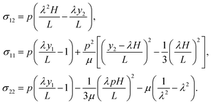 | (20) |
These results reproduce those in the previous paper.13
3. Leak by elastic deformation
A seal may leak by elastic deformation (Section 3), or by rupture (Section 4). Liu et al. proposed a criterion for leak by elastic deformation.9 Before the pressure of the fluid is applied, the two rigid walls compress the elastomer in a homogenous state (Fig. 3a). When a small fluid pressure p is applied in the upstream region of the seal, the elastomer deforms slightly (Fig. 3b). The contact pressure between the top wall and the elastomer drops linearly along the length of the seal. The maximum contact pressure σmax occurs at the upstream corner so that σmax= −σ22 at (y1 = u(h), y2 = h). When p is low, σmax is higher than p, preventing the fluid from penetrating through the top interface, and the seal does not leak. When the fluid pressure reaches a critical value pc, the fluid pressure matches the maximum contact pressure, pc = σmax (Fig. 3c). The contact pressure in the interior of the sealed region still drops linearly below the fluid pressure, and the seal leaks.
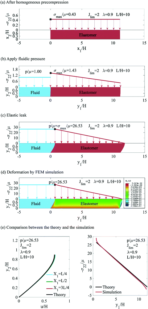 |
| | Fig. 3 A seal leaks by elastic deformation. (a) Before the fluid pressure is applied, the precompression causes a homogeneous contact pressure. (b) When the fluid pressure is lower than the maximum contact pressure, the seal does not leak. (c) When the fluid pressure reaches the contact pressure, the seal leaks. (d) Contour plot of displacement of the seal under fluidic pressure from FEM simulation, using the same parameters as in (c). The color bar shows the displacement of seal in y2 direction. (e) Comparisons between the theoretical results based on eqn (1) and the FEM simulation results. Left: Displacements of material segments at X1 = L/4, L/2, and 3L/4 along the seal are plotted. Right: Contact stress at top surfaces at the current location under fluidic pressure. | |
For the neo-Hookean material, the critical condition for leak by elastic deformation can be obtained in an analytical form. Substitute the position of the upstream corner (y1 = u(h), y2 = h) into the normal stress σ22 in eqn (20), we obtain that the contact pressure at the upstream corner is13
| |  | (21) |
When the pressure is small, the maximum contact pressure is dominated by the linear term of
p. As pressure increases, the negative quadratic term of
p begins to reduce the rising trend of contact pressure. Eventually, the maximum contact pressure will meet the applied pressure. The critical condition for leak by elastic deformation predicts that the leak pressure takes the form
| |  | (22) |
To rationalize the displacement field in the form of eqn (1), we use the Abaqus software to perform a two-dimensional finite element calculation for the strain-stiffening material (Fig. 3d). We compare the calculated displacement field to that of eqn (1), and find them to be close in the entire seal except for small regions near the edges (Fig. 3e). Also compared is the contact stress between the seal and the top substrate.
For a strain-stiffening seal, the critical condition for leak by elastic deformation is determined numerically. We plot the p–Q curves for strain-stiffening seals with Jlim = 2 and 10 and for a neo-Hookean seal (Fig. 4). With the same geometric parameters, λ=0.8 and L/H = 10, the strain-stiffening seal enhances the leak pressure by 3.2 times and reduces the extrusion of volume by ∼30% compared to the neo-Hookean seal. The sealing capacity can be further enhanced by modifying material and geometric parameters.
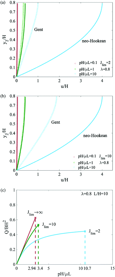 |
| | Fig. 4 (a and b) Displacement of seals for both strain-stiffening (open circle) and neo-Hookean (solid line) materials under different fluid pressures. (c) Relation between the fluid pressure p and the extrusion volume Q, plotted in the dimensionless form for both strain-stiffening (Jlim = 2, 10) and neo-Hookean (Jlim → ∞) materials. Cross markers are critical points for seals to leak by elastic deformation. | |
Fig. 5 shows the dependence of the critical pressure pc and extruded volume Qc on various parameters (i.e., Jlim, λ, and L/H). Reducing Jlim can increase sealing pressure by one order of magnitude. Depending on the precompression, the enhancement is dramatic when Jlim < 5 for λ = 0.8, and when Jlim < 2 for λ = 0.8 (Fig. 5a). The precompression stiffens the seal before the pressure is applied. A larger precompression (smaller λ) elevates sealing capacity significantly (Fig. 5c). The leaking pressure pc scales with the aspect ratio L/H linearly (Fig. 5e). At the same time, a smaller Jlim will reduce the extrusion of elastomers (Fig. 5b). For a less precompressed seal, the leak occurs much easier, and the extrusion of elastomer is less (Fig. 5d). The aspect ratio L/H has no effect on the extrusion volume (Fig. 5f).
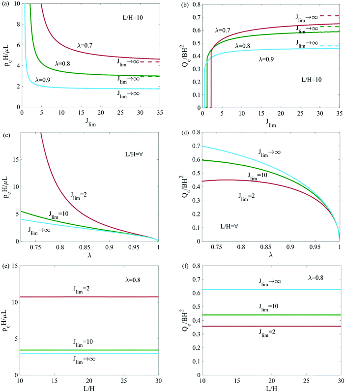 |
| | Fig. 5 The critical pressure pc and extrusion volume Qc for elastic leak as functions of Jlim, λ, and L/H. | |
4. Leak by rupture
We next turn to leak by rupture, in which a crack tunnels from one end of the seal to the other. In a previous paper,13 rupture was assumed to take place in a neo-Hookean material. Here we extend the model by analyzing rupture in a Gent material. The initial crack of length lc under the homogeneously precompressed state is located at the bottom of the upstream front of the seal (Fig. 6b). Assume that both the top surface of the seal and the crack are frictionless. When the crack length is large compared to the height of the seal, the crack propagates in a steady state. Far ahead of the crack front, the elastomer is bonded to the bottom wall, and the deformation varies with y2, as described in the previous section. Far behind the crack front, the elastomer is debonded from the bottom wall, and the deformation is homogenous.
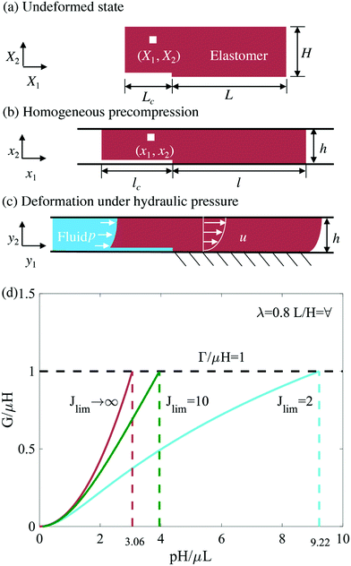 |
| | Fig. 6 A model of rupture. (a–c) The model assumes a debonded region of length lc located at the bottom of the upstream front of the seal. (d) The relation between energy release rate G and pressure p. A strain-stiffening material will enhance the critical pressure of rupture compared to a neo-Hookean material. | |
When the crack propagates by length dLc in the undeformed state (Fig. 6a), the crack propagates by dlc = dLc/λ in the deformed state (Fig. 6b). Associated with the propagation of the crack, the bonded part of the elastomer reduces, which reduces the strain energy by  . The debonded part of the elastomer increases, which increases the strain energy by BW(λ)hdlc. The increase of the crack area in the reference state is BdLc. By definition, the energy release rate G is the reduction of the elastic energy in the deformed state divided by the area of crack extension in the reference state:
| |  | (23) |
Observe that the energy release rate (
eqn (23)) is calculated using the difference in the potential energy far ahead of the crack and far behind the crack. Consequently, the energy release rate is the same whether the crack is on the interface or in the interior of the seal. The condition of rupture is
G =
Γ, where
Γ is either the toughness of the elastomer or the elastomer/wall interface. For a strain-stiffening seal, the numerical calculation is carried out to determine the energy release rate
G in
eqn (23). Dimensional analysis indicates that the dimensionless energy release rate
G/
μH is a function of dimensionless pressure
p/
μ, aspect ratio
L/
H, precompression
λ, and
Jlim. Taking the fracture condition that
G =
Γ, the dependence of the pressure of rupture
pf is
| |  | (24) |
The energy release rate for the neo-Hookean seal is13
| |  | (25) |
The critical condition of the crack growth
G =
Γ gives the pressure of rupture for a neo-Hookean seal as
| |  | (26) |
To illustrate, we include the
p–
G curves to rupture for both a neo-Hookean seal and strain-stiffening seals with
Jlim = 2 and 10 (
Fig. 6d). With the same
λ = 0.8 and
Γ/
μH = 1, the strain-stiffening seal enhances the rupture pressure compared to the neo-Hookean seal.
Fig. 7 shows the dependence of pressure pf and extrusion volume Qf for rupture on Jlim, λ, L/H, and Γ/μH. The rupture pressure of strain-stiffening seals increases significantly with the reduction of Jlim, especially when Jlim < 10. Before rupture, the extrusion volume of strain-stiffening seals decreases with Jlim. The precompression stiffens the seal before a fluid pressure is applied, thus a larger precompression (smaller λ) elevates the rupture pressure of strain-stiffening seals. Consequently, the extrusion volume before rupture is reduced as precompression increases. The rupture pressure scales with the aspect ratio L/H linearly, but the extrusion volume has no dependence on the aspect ratio L/H.
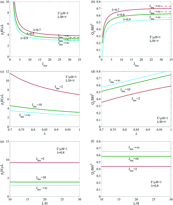 |
| | Fig. 7 The pressure pf and extrusion volume Qf for rupture as functions of Jlim, λ, and L/H. | |
5. Diagram of failure modes
To leak by elastic deformation, or to leak by rupture? If a seal leaks before the material is damaged, one can reduce the fluid pressure below the leak pressure to recover the sealing capacity. The leak by elastic deformation might serve as a design principle for a safety valve. If a seal leaks by rupture, the loss of sealing capacity is irreversible, unless a self-healing material is used. In this section, we discuss how the two modes of leak are affected by various parameters.
For a given seal material and its geometric parameters, we can draw a diagram by comparing the critical pressures for the two modes of leak. In Fig. 8a, we summarize the leak modes for various Jlim and λ, while other parameters L/H and Γ/μH are fixed. For a neo-Hookean material, Jlim → ∞, the boundary between leak by elastic deformation and by rupture is:
| |  | (27) |
When
Γ/
μH = 1,

.
Fig. 8a shows that a strain-stiffening seal under a larger precompression (smaller
λ) leaks by rupture. For a small
Jlim, typically
Jlim < 8, leak by elastic deformation can be avoided even at a slight precompression. Leak modes are also represented on the plane of
λ and
Γ/
μH for strain-stiffening seals and a neo-Hookean seal (
Fig. 8b–d).
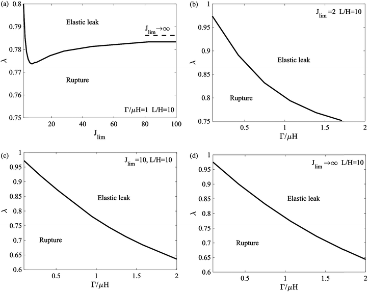 |
| | Fig. 8 Leak by elastic deformation and leak by rupture are demarcated on planes of various axes. (a) The diagram in the Jlim–λ plane for strain-stiffening seals with the fixed Γ/μH and L/H. (b) The diagrams in the Γ/μH–λ plane for strain-stiffening seals with the fixed Jlim and L/H. (c) The diagrams in the Γ/μH–λ plane for neo-Hookean seals with the fixed L/H. | |
6. Friction at the top surface
Considering a frictional stress at the top surface of the seal σ12 (y2 = h) = σh, the boundary conditions change the coefficients b and c in eqn (6). According to the free body diagram (Fig. 9a, σ12 is shown in the defined positive direction), σ12 in eqn (7) becomes| |  | (28) |
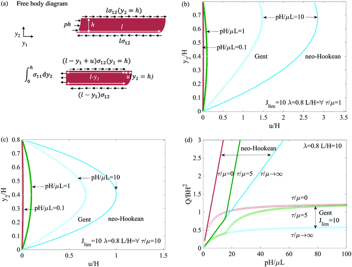 |
| | Fig. 9 (a) Free body diagram of the seal with friction at the top. (b and c) Displacement u of seal materials at height of y2. τ/μ is the dimensionless friction on the upper boundary. (d) p–Q curves for both strain-stiffening (Gent) and neo-Hookean seals when friction at the top surface of the seal is considered, assuming no leak happens. | |
For a neo-Hookean material, eqn (19) becomes
| |  | (29) |
and for a Gent material,
eqn (13) becomes
| |  | (30) |
A solution for displacement can be obtained:
| | 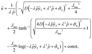 | (31) |
where
| | 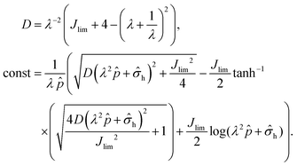 | (32) |
In the non-sliding stage, the displacement
u = 0 at
y2 =
h, and this determines a static frictional stress
σh = −
pHλ2/2
L. In the sliding stage, note the sliding stress at
y2 =
h as
τ. Assume the static frictional stress is below the sliding stress,
pHλ2/2
L <
τ, so that the shear stress is the constant sliding stress,
σh = −
τ. The transition between these two stages occurs when fluid pressure
p = 2
Lτ/
Hλ2.
Employing these equations and conditions in calculations, we plot distributions of displacement (Fig. 9b and c). Compared with Fig. 4a and b, the displacement of the seal near the top surface is constrained by friction, and the maximum displacement is reduced. We also plot p–Q curves (Fig. 9d). For simplicity, the critical pressure for both leaks by elastic deformation and by rupture is not considered in this plot. Compared with Figure 4c, the transition from static friction to sliding friction has an effect on the extrusion volume of the seal. For both strain-stiffening and neo-Hookean seals, larger friction will limit the extrusion of the seal.
We plot the strain energy density (W) and stresses in the seal in y2 direction when friction is a concern (Fig. 10). The minimum strain energy density in the seal is shifting from the upper surface to the center along with y2 when the friction at the upper surface increases. Similarly, the shear stress σ12 becomes more antisymmetric when the friction is larger. Larger friction will also increase the contract stress, but not significantly.
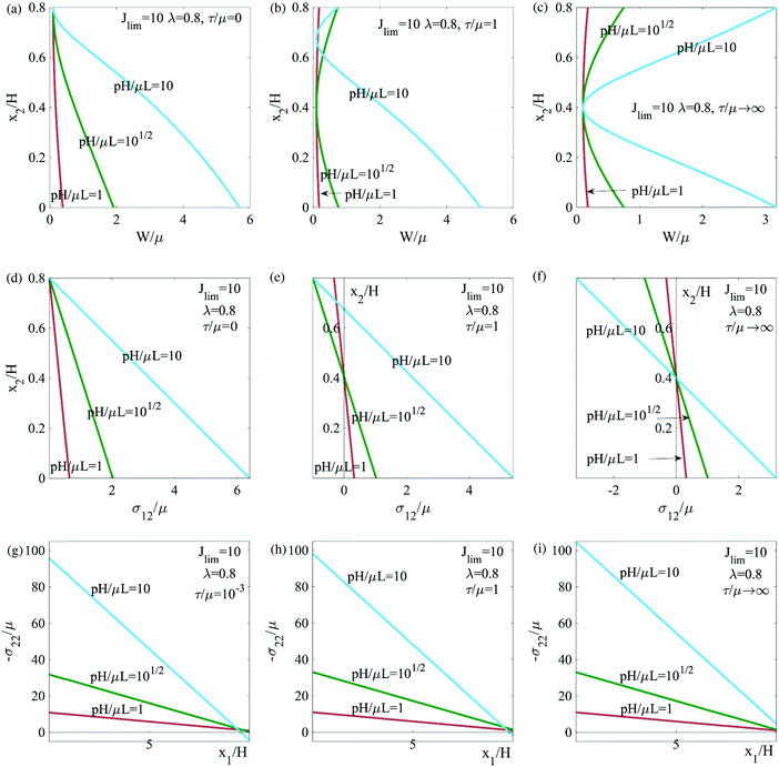 |
| | Fig. 10 Distributions of the elastic energy density of seal W/μ and stresses σ12 and σ22 under the deformation. | |
7. Conclusion
A seal needs to be both soft to accommodate installations and stiff to block fluid flow. We investigate the ability of strain-stiffening materials to enhance sealing pressure as compared to neo-Hookean materials. A strain-stiffening seal is soft initially but stiffens steeply. We calculate the deformation field using an approach analogous to the lubrication theory. We focus on two modes of leak, by elastic deformation and by rupture. For both modes of leak, the sealing capacity of a strain-stiffening seal increases several times compared to a neo-Hookean seal. Modes of leak are represented in planes of various parameters. We have also considered the case that friction exists between the seal and the top wall. It is hoped that these results will aid in the development of materials and geometries of seals.
Conflicts of interest
There are no conflicts to declare.
Acknowledgements
This work is supported by NSF Materials Research Science and Engineering Centers (Grant DMR-2011754), and by the Air Force Office of Scientific Research (FA9550-20-1-0397).
References
-
R. Evers, D. Young, G. Vargus and K. Solhaug, SPE Annual Technical Conference and Exhibition, One Petro, 2008 Search PubMed.
- H. Patel, S. Salehi, R. Ahmed and C. Teodoriu, J. Petrol. Sci. Eng., 2019, 179, 1046–1062 CrossRef CAS.
- D. W. Yun, K. Jinho and S. H. Kim, Adv. Mater. Res., 2012, 378, 759–762 Search PubMed.
-
N. S. Currey, Aircraft landing gear design: Principles and practices, Aiaa, 1988 Search PubMed.
- M. M. Guest, T. P. Bond, R. G. Cooper and J. R. Derrick, Science, 1963, 142, 1319–1321 CrossRef CAS PubMed.
- Y.-H. V. Ma, K. Middleton, L. You and Y. Sun, Microsyst. Nanoeng., 2018, 4, 1–13 CrossRef PubMed.
- V. R. Sherman, W. Yang and M. A. Meyers, J. Mech. Behav. Biomed. Mater., 2015, 52, 22–50 CrossRef CAS PubMed.
-
R. K. Flitney, Seals and sealing handbook, Elsevier, 2011 Search PubMed.
- Q. Liu, Z. Wang, Y. Lou and Z. Suo, Extreme Mech. Lett., 2014, 1, 54–61 CrossRef.
- Z. Wang, Q. Liu, Y. Lou, H. Jin and Z. Suo, J. Appl. Mech., 2015, 82, 081010 CrossRef.
- Y. Lou and S. Chester, Int. J. Appl. Mech., 2014, 6, 1450073 CrossRef.
- B. Druecke, E. Dussan, V. N. Wicks and A. Hosoi, J. Appl. Phys., 2015, 117, 104511 CrossRef.
- Z. Wang, C. Chen, Q. Liu, Y. Lou and Z. Suo, J. Mech. Phys. Solids, 2017, 99, 289–303 CrossRef.
-
L. Treolar, The physics of rubber elasticity, Clarendon, 1975 Search PubMed.
- S. Motte and L. J. Kaufman, Biopolymers, 2013, 99, 35–46 CrossRef CAS PubMed.
- A. N. Gent, Rubber Chem. Technol., 1996, 69, 59–61 CrossRef CAS.
- X. Zhao and Z. Suo, Phys. Rev. Lett., 2010, 104, 178302 CrossRef PubMed.
- L. Jin and Z. Suo, J. Mech. Phys. Solids, 2015, 74, 68–79 CrossRef.
- E. M. Arruda and M. C. Boyce, J. Mech. Phys. Solids, 1993, 41, 389–412 CrossRef CAS.
- M. Vatankhah-Varnosfaderani, W. F. Daniel, M. H. Everhart, A. A. Pandya, H. Liang, K. Matyjaszewski, A. V. Dobrynin and S. S. Sheiko, Nature, 2017, 549, 497–501 CrossRef PubMed.
- M. Jaspers, M. Dennison, M. F. Mabesoone, F. C. MacKintosh, A. E. Rowan and P. H. Kouwer, Nat. Commun., 2014, 5, 1–8 Search PubMed.
- Y. Ma, K. I. Jang, L. Wang, H. N. Jung, J. W. Kwak, Y. Xue, H. Chen, Y. Yang, D. Shi and X. Feng, Adv. Funct. Mater., 2016, 26, 5345–5351 CrossRef CAS PubMed.
- J. Luo, S. Li, J. Xu, M. Chai, L. Gao, C. Yang and X. Shi, Adv. Funct. Mater., 2021, 31, 2104139 CrossRef CAS.
Footnote |
| † These authors contributed equally. |
|
| This journal is © The Royal Society of Chemistry 2022 |
Click here to see how this site uses Cookies. View our privacy policy here.  a,
Chao
Chen†
ab,
Yucun
Lou
cd and
Zhigang
Suo
 *a
*a


 and
and  , we find that the field of stress takes the following form
 , and a horizontal shear force (l − y1)b, where the bottom surface does not slide, u(y2 = 0) = 0. The balance of the forces acting on the seal in the horizontal direction gives that
  . So far, we can write the field of stress as


![[p with combining circumflex]](https://www.rsc.org/images/entities/i_char_0070_0302.gif) = pH/μL. The analytical solution of û is
= pH/μL. The analytical solution of û is


 . The debonded part of the elastomer increases, which increases the strain energy by BW(λ)hdlc. The increase of the crack area in the reference state is BdLc. By definition, the energy release rate G is the reduction of the elastic energy in the deformed state divided by the area of crack extension in the reference state:


 . Fig. 8a shows that a strain-stiffening seal under a larger precompression (smaller λ) leaks by rupture. For a small Jlim, typically Jlim < 8, leak by elastic deformation can be avoided even at a slight precompression. Leak modes are also represented on the plane of λ and Γ/μH for strain-stiffening seals and a neo-Hookean seal (Fig. 8b–d).


