
Deciphering the carrier dynamics enhancement in WO3-containing composites: an ultrafast transient reflectance investigation†
Haijuan
Zhang
 *ab,
Tianxiang
Jiang
c,
Meiqiong
Zhan
a,
Haiping
Li
*d and
Faming
Lu
*b
*ab,
Tianxiang
Jiang
c,
Meiqiong
Zhan
a,
Haiping
Li
*d and
Faming
Lu
*b
aSchool of Mathematics, Physics and Statistics, Shanghai Polytechnic University, Shanghai 201209, China. E-mail: hpli@sdu.edu.cn
bCenter for Ultrafast Science and Technology and School of Physics and Astronomy, Shanghai Jiao Tong University, Shanghai 200240, China. E-mail: faming.lu@sjtu.edu.cn
cSchool of Energy and Materials, Shanghai Polytechnic University, Shanghai 201209, China
dNational Engineering Research Center for Colloidal Materials, School of Chemistry and Chemical Engineering, Shandong University, Jinan 250100, China
First published on 25th July 2024
Abstract
In recent years, the quest for WO3-based composites with expanded optical absorption and elevated photocatalytic and photoelectrochemical performance has intensified. Despite these pursuits, a clear mechanistic understanding of the efficiency gains has been a missing piece, hindering further optimization. This study uses the transient reflectance (TR) technique to probe the intricacies of carrier dynamics in WO3, Li0.1WO3, and the FeOOH/Li0.1WO3 composite, and found that under near-ultraviolet (NUV) illumination, the FeOOH/Li0.1WO3 system demonstrates a photo-carrier lifetime that is approximately twofold and tenfold longer than that of Li0.1WO3 and WO3, respectively. Moreover, under near-infrared (NIR) irradiation, the FeOOH/Li0.1WO3 composite sustains carriers for nearly four times longer than the Li0.1WO3 counterpart. Our in-depth analysis points to the hole-filling effect from lithium intercalation and the FeOOH-mediated passivation of oxygen vacancies as the dual drivers behind the significantly extended carrier lifetimes, which favor processes such as charge separation, transfer, extraction, and storage. By employing femtosecond TR measurements to dissect the photo-carrier behavior in these systems, this study sheds light on the intrinsic mechanisms that have been obscured using traditional approaches. This work aims to contribute pivotal insights, potentially paving the way for the next generation of high-performance WO3 composites in energy conversion technologies.
 Haijuan Zhang | Dr Haijuan Zhang is currently an assistant research fellow at the School of Mathematics, Physics and Statistics, Shanghai Polytechnic University, China. She received her B.S. (2008) and M.S. (2011) degrees in School of Physics and Electronics, Shandong Normal University, China, and her PhD degree (2015) in School of Information Science and Engineering, Shandong University, China. Her research interests include ultrafast spectroscopy, ultrafast X-ray diffraction, ultrafast carrier dynamics in photoelectric materials and strongly correlated electronic systems. |
Introduction
Tungsten oxides (WOx, where x ≤ 3) stand as pioneers among visible light-responsive semiconductors and have long been celebrated for their exceptional attributes, including high electron mobility, remarkable electron transfer and storage capabilities, and commendable electrochemical stability – all of which are coupled with the advantage of being earth-abundant.1 Their potential shines brightly in photocatalysis and photoelectrochemistry. However, the unadorned WOx struggles with relatively low efficiency, primarily due to the swift recombination of photo-generated electrons (e−) and holes (h+). Moreover, WOx's optical absorption is confined to the near-ultraviolet (NUV) to visible spectrum, which captures only a fraction of the solar spectrum, as over half of the sun's energy lies in the near-infrared (NIR) region.In recent years, the pursuit of WOx-containing composites with enhanced carrier behaviors and an expanded optical absorption spectrum has seen some remarkable advancements. For example, the typical band gap of WOx, which ranges from 2.6 to 2.8 eV, can be narrowed to approximately 0.6–0.9 eV by embedding cations such as H+, Li+, Na+, K+, and Cs+ into the tunneling hexagonal structured WO3, which extends the absorption spectrum from NUV to NIR.2–4 Furthermore, coupling WOx with other semiconductors like C3N4, BiVO4, and FeOOH has been shown to significantly enhance the charge carrier separation efficiency, which in turn boosts electron transfer and storage capacities.3,5–8 The broadening of the absorption spectrum is attributed to the formation of a new valence band, which is supplied by the partially occupied 5d orbitals of W5+ ions.2 Despite these strides, a comprehensive understanding of the mechanisms that enhance carrier dynamics remains obscured, thereby hindering further optimization of material performance.
Traditionally, time-resolved photoluminescence (TRPL) has been the technique of choice for probing photo-carrier dynamics in photocatalytic (PC)/photoelectrochemical (PEC) systems.9–11 However, TRPL faces limitations when it comes to examining the NIR region, where low photoluminescence quantum yields pose a challenge for detection.12 Furthermore, the complexity of PC/PEC processes, which involve a cascade of interrelated carrier reactions such as generation, transfer, hole filling, trapping, and recombination, complicates the picture. While TRPL is a powerful tool for studying slower dynamics like carrier trapping and recombination, it may introduce significant uncertainties when measuring ultrafast carrier dynamics on the order of picoseconds, such as hole filling.10,12
In this study, we introduce transient reflectance (TR) spectroscopy with femtosecond time resolution to elucidate the carrier dynamics in PC/PEC systems. This technique has allowed us to capture the behavior of photo-carriers in Li0.1WO3 with broadened optical absorption, and FeOOH/Li0.1WO3 with superior PC/PEC performance,8,13,14 using pristine WO3 as the control. Our TR findings reveal that under 400 nm illumination, photo-carriers in FeOOH/Li0.1WO3 endure more than twice as long as those in Li0.1WO3 and ten times longer than those in WO3. Under 800 nm illumination, the FeOOH/Li0.1WO3 composite sustains photo-carriers nearly four times longer than the Li0.1WO3 alone. Further analysis indicates that the significantly extended carrier lifetimes in FeOOH/Li0.1WO3, which favor processes such as charge separation, transfer, extraction, and storage, could be attributed to the hole-filling effect from lithium intercalation and the passivation of oxygen vacancy defects by FeOOH. By delving into the factors influencing photo-carrier behavior in these sunlight harvesting systems using femtosecond TR measurements, this study aims to offer novel insights into the intrinsic mechanisms that may have been elusive using conventional methods.
Experiments and results
Static characterizations
WO3 and Li0.1WO3 were synthesized via an in situ solvothermal approach, while the FeOOH/Li0.1WO3 composite was fabricated by depositing FeOOH onto the surface of Li0.1WO3 nanorods. Detailed procedures for sample preparation are delineated in the ESI,† S1. Conventionally, WO3 synthesized using this method adopts an orthorhombic crystal structure. However, the incorporation of lithium through intercalation provides both Li0.1WO3 and FeOOH/Li0.1WO3 with a pure hexagonal phase of WO3,2,3,15,16 in accordance with the joint committee on powder diffraction standards (JCPDS) reference 33-1387. This phase purity is corroborated by the X-ray diffraction (XRD, ARL Equinox 3500) patterns presented in Fig. 1a. It is noteworthy that, due to the amorphous nature of FeOOH in the FeOOH/Li0.1WO3 composite, no distinct diffraction signals attributable to FeOOH were detected in the XRD analysis. | ||
| Fig. 1 (a) XRD patterns of Li0.1WO3 and FeOOH/Li0.1WO3; (b) Tauc plots of the UV-vis-NIR absorption spectra (inset) of WO3, Li0.1WO3 and FeOOH/Li0.1WO3; (c) TDOS spectra of Li0.1WO3 as well as WO3 for comparison; and (d) schematic diagram of the band structure of WO3 and Li0.1WO3 (or FeOOH/Li0.1WO3) based on the absorption spectra. | ||
The inset of Fig. 1b presents the absorption spectra for the trio of samples, as measured using a UV-vis-NIR spectrophotometer (Lambda 950, PerkinElmer, UK). To elucidate the energy structural properties, a detailed analysis of the absorption spectra was conducted employing the Tauc equation, represented as (αhν)n = B(hν − Eg),17 where α signifies the absorption coefficient, hv denotes the photon energy, B is a proportionality constant, Eg is the band gap energy, and n equals 1/2 for an indirect-bandgap semiconductor, as depicted in Fig. 1b. The optical data reveal that all samples exhibit robust absorption in the NUV region, characterized by an absorption edge of approximately 2.68 eV, indicated by the green dotted line in Fig. 1b. Furthermore, Li0.1WO3 and FeOOH/Li0.1WO3 manifest an additional absorption band in the visible to near-infrared (vis-NIR) region, evidenced by a reduced band edge of approximately 0.78 eV, marked by the red dotted line in Fig. 1b. The former represents the intrinsic band gap energy of WO3, whereas the latter is induced by Li+ intercalation, which can be explained by the energy distribution of the density of states (DOS) derived from first-principles calculations. The DOS results depicted in Fig. 1c show that in WO3, the 2p orbitals of O2− are fully occupied, and the 5d orbitals of W6+ are vacant, constituting the valence band (VB, also noted as VB1 for Li0.1WO3 and FeOOH/Li0.1WO3 for distinguishing from VB2) and the conduction band (CB), respectively, as illustrated in the left panel of Fig. 1d.2,18 When lithium is incorporated to form Li0.1WO3, the Fermi level (Ef) shifts upward towards the CB, as compared to the pristine WO3. Moreover, nearly all lithium metal atoms contribute to the upper CB, indicating that they are effectively ionized, thereby providing a substantial supply of free electrons. As a result, the originally vacant 5d orbitals of W6+ become partially filled, leading to the formation of W5+. These partially filled 5d orbitals of W5+ create a new valence band (VB2) positioned below the CB, which accounts for the visible to near-infrared (vis-NIR) absorption, as shown in the right panel of Fig. 1d. Additionally, as shown in Fig. 1a, the absorption spectra of Li0.1WO3 and FeOOH/Li0.1WO3 are strikingly similar, both differing from that of FeOOH.19 This similarity suggests that FeOOH/Li0.1WO3 shares a comparable spectroscopic mechanism with Li0.1WO3, and the incorporation of FeOOH has minimal impact on the primary energy structure of the latter.
The interpretation of the optical characteristics is corroborated by X-ray photoelectron spectroscopy (XPS, Thermo Scientific ESXCALAB Xi+) analysis. Fig. S1 in the ESI,† S2 displays the survey XPS spectra for the three samples. The spectra reveal not only the ubiquitous presence of W and O elements but also the distinct presence of Li and Fe, confirming the successful incorporation of Li and FeOOH into Li0.1WO3 and FeOOH/Li0.1WO3, respectively. The Li 1s XPS spectrum for Li0.1WO3, as shown in Fig. 2a, is deconvoluted into two peaks: a principal peak at 56.3 eV and a shoulder peak at 58.1 eV. The latter is indicative of the interaction between Li and the lattice oxygen in Li0.1WO3, while the former is attributed to Li+ ions within the hexagonal tunnels of WO3,20,21 consistent with the DOS calculations suggesting complete ionization of lithium atoms in Li0.1WO3.
 | ||
| Fig. 2 (a) Li 1s XPS spectrum of Li0.1WO3 and W 4f XPS spectra of (b) WO3, (c) Li0.1WO3 and (d) FeOOH/Li0.1WO3. | ||
Additionally, the induced presence of W5+ ions, a consequence of Li+ intercalation, is detectable. Fig. 2b–d illustrate that the W 4f spectra for all three samples can be decomposed into two doublets: one for W6+ at 35.5 and 37.6 eV, and another for W5+ at 34.3 and 36.4 eV, respectively, indicating the presence of W5+ ions in each sample. In WO3, the W5+ ion peak area ratio of 3.15% is likely due to oxygen vacancy (OV) defects.22 In Li0.1WO3, this ratio increases almost twofold to 5.26%, which can be attributed to lithium intercalation and is further explained as follows: In the hexagonal Li0.1WO3 crystal structure, with uniformly dispersed trigonal and hexagonal tunnels, the intracrystalline hexagonal tunnels exhibit a high affinity for Li+ ions, which can be represented by the equation WO3 + Li+ + e− ⇄ [WO3−Li+].2,3,15 This process allows for the introduction of a significant number of Li+ ions, leading to the reduction of a substantial amount of W6+ to W5+ to maintain the charge balance, thereby increasing the W5+ ratio in Li0.1WO3 compared to WO3. When Li0.1WO3 is combined with FeOOH, the W5+ ratio decreases to 4.15%. Prior research has indicated that the amorphous FeOOH layer may partially passivate OVs in the material.23 The reduction in the W5+ ratio in FeOOH/Li0.1WO3 is likely due to the depopulation of OVs passivated by FeOOH.
Ultrafast transient reflectance (TR) measurements and data analysis
As previously outlined, the loading of FeOOH has a negligible effect on the energy structure of Li0.1WO3. Therefore, the dynamic spectral features of FeOOH/Li0.1WO3, detailed in the subsequent discussion, are primarily ascribed to the photo-carriers originating from Li0.1WO3 rather than FeOOH. In the TR measurements, two distinct pump wavelengths were employed: a 400 nm wavelength to provide insights into the photo-carrier dynamics across all samples under visible light irradiation, and an 800 nm wavelength to explore those of Li0.1WO3 and FeOOH/Li0.1WO3 under NIR irradiation. Meanwhile, an 800 nm wavelength was consistently utilized as the probe regardless of which pump is used. Additional specifics of the TR experimental setup are elaborated in the ESI,† S3.Fig. 3 and 4 display the TR measurement results for the 400 nm and 800 nm excitations, respectively. Following 400 nm excitation, Fig. 3 indicates that the three samples respond differently to the 800 nm probe. Specifically, WO3 shows a decrease in reflectance at 800 nm, while Li0.1WO3 and FeOOH/Li0.1WO3 exhibit an opposite trend. This variation in response is likely due to the distinct band structure distributions of the materials, as further discussed in the ESI,† S4. It is recommended that, while different samples may exhibit varied responses to the 800 nm probe, the probe should consistently capture the dynamics of photo-carriers within the CBs of all samples.
 | ||
| Fig. 3 (a)–(c) The pump fluence dependent TR kinetics for WO3, Li0.1WO3 and FeOOH/Li0.1WO3 under 400 nm illumination, respectively. (d) The normalized TR traces for three samples at a pump fluence of 340 μJ cm−2. Inset of (a): plots of (ΔRt/R)max as a function of pump fluence. Black solid curves in (a)–(c) are fitting curves using eqn (1) for the extraction of the depopulation rate constants k1 and k2. | ||
 | ||
| Fig. 4 (a) and (b) The pump fluence dependent TR kinetics for Li0.1WO3 and FeOOH/Li0.1WO3 under 800 nm illumination, respectively; (c) plots of (ΔRt/R)max as a function of pump fluence; (d) normalized TR traces for two samples at a pump fluence of 220 μJ cm−2. Black solid curves on (a) and (b) are fitting curves using eqn (1) for the extraction of the depopulation rate constants k1 and k1. | ||
The dynamics triggered by 400 nm excitation primarily involve two processes: a rapid change in reflectivity to the maximum (ΔRt/R)max within the first picosecond, and a slower recovery process that extends over tens to hundreds of picoseconds. The former is typically assigned to the photo-induced e−/h+ assemblage on the CB/VB right after the photon illumination, while the latter should be linked to the relaxation of these photo-carriers through mechanisms like defect trapping and electron–hole recombination.24 Obviously, photo-carriers in WO3 relax much more quickly than those in Li0.1WO3 and FeOOH/Li0.1WO3, as illustrated in Fig. 3d. For the 800 nm excitation, except for the above two processes, an additional quick recovery process of less than 2 ps is observed. Considering that the photon energy of 800 nm (1.55 eV) is much larger than the band gap (0.78 eV) traversed, the initially excited carriers should carry much excess energy. The above quick recovery should be the dissipation process of the excess energy through phonon radiation.25 These carrier assemblage and excess energy dissipation processes are normal and have been well-documented in many semiconductors and insulators,26,27 thus they will not be further discussed here. In the following, we aim to interpret the complex slow recovery process on a time scale to uncover the underlying mechanisms that boost the superior PC/PEC performances of these materials.
As is known to all, when materials are illuminated by photons with energy exceeding the band gap, electrons will be excited from the VB to assemble on the CB. The concentration of these excited electrons assembled on the CB, denoted as n0, can be determined using the formula n0 = Fa/hv, where F represents the incident photon fluence, α is the material's absorption coefficient at the pump wavelength, and hv corresponds to the pump photon energy. As illustrated in the inset of Fig. 3a and c, under both 400 nm and 800 nm excitation, the maximum relative change in reflectivity, |ΔRt/R|max, scales linearly with the pump fluence F (or equivalently, n0) for all samples which leads to the connection as |ΔRt/R|max = bn0 with a linear coefficient b. We further hypothesize that the transient reflectivity change ΔRt/R and the transient electron density nt are governed by the same recovery function f(t), such that ΔRt/R = |ΔRt/R|max·f(t) = bn0·f(t) = bnt. Therefore, the observed slow recovery is indicative of the electron depopulation process within the probed volume.
In semiconductors, the depopulation photo-carriers is typically described by the rate equation −dnt/dt = k1nt + k2nt2 + k3nt3,25,28 where the terms on the right-hand side correspond to: (1) first-order trap state-mediated recombination; (2) second-order non-geminate or free carrier recombination; and (3) three-body Auger recombination.29 Here, k1, k2 and k3 are the respective depopulation rate constants. Given the low pump fluence (100–580 μJ cm−2) used in this study, Auger recombination can be disregarded. Consequently, the rate equation simplifies to −dnt/dt = k1nt + k2nt2, whose analytic solution is given by
| nt = k1n0/[(k2n0 + k1)ek1t − k2n0]. | (1) |
By fitting the recovery processes of the three samples with eqn (1), as depicted by the solid black curves in Fig. 3a–c and 4a and b, the corresponding depopulation rate constants k1 and k2 can be extracted. For all the samples, the fluctuation of the extracted constants across different pump fluences is minimal; thus, an average value from all fluences ranging from 100 to 580 μJ cm−2 is used for the discussion, as listed in Table 1. By calculating k2 × n0 (Table 1) and comparing it with k1, we found that the former is consistently two or three orders of magnitude smaller than the later. According to eqn (1), this suggests that the contribution of the second-order mechanisms is significantly weaker. In other words, the electron depopulation processes are predominantly governed by the first-order trap state-mediated recombination. This conclusion is further supported by a more detailed analysis provided in the ESI,† S5. Consequently, the subsequent discussion will primarily focus on the first-order mechanism, as characterized by k1, for further analysis.
| Pump wavelength | Sample | k 1 (×109 s−1) | k 2(×10−12 cm3 s−1) | k 2 × n0 (×107 s−1) |
|---|---|---|---|---|
| 400 nm | WO3 | 4.00 | 6.32 | 8.40 |
| Li0.1WO3 | 0.65 | 0.88 | 1.17 | |
| FeOOH/Li0.1WO3 | 0.36 | 0.39 | 0.47 | |
| 800 nm | Li0.1WO3 | 9.75 | 38.3 | 99.0 |
| FeOOH/Li0.1WO3 | 2.16 | 9.00 | 13.0 |
As detailed in Table 1, the depopulation rate constant k1 exhibits a pronounced sample-dependent behavior under both 400 nm and 800 nm excitation. Specifically, under 400 nm excitation, the value of k1 for WO3 is observed to be 4.00 × 10⁹ s−1, which diminishes to 0.65 × 10⁹ s−1 for Li0.1WO3 and further to 0.36 × 10⁹ s−1 for FeOOH/Li0.1WO3, reflecting a reduction by factors of 6 and 10, respectively. Meanwhile, under 800 nm excitation, k1 for Li0.1WO3 is approximately 9.75 × 10⁹ s−1, which declines to approximately 2.16 × 10⁹ s−1 for FeOOH/Li0.1WO3, indicating a reduction by a factor of 4. According to eqn (1), a lower k1 signifies a slower electron depopulation rate, which in turn implies a longer electron lifetime, and vice versa. Consequently, the dynamic measurements suggest that the electron lifetime in FeOOH/Li0.1WO3 is extended compared to that in Li0.1WO3, and both are substantially longer than the lifetime observed in pure WO3.
Discussion
Notably, TR measurements indicate that under 400 nm excitation, the electron lifetime in the FeOOH/Li0.1WO3 composite is approximately twice that in Li0.1WO3 and nearly tenfold that in WO3. Meanwhile, under 800 nm excitation, the electron lifetime in FeOOH/Li0.1WO3 is roughly four times longer than in Li0.1WO3, as detailed in Table 1. We now explore the potential mechanisms that contribute to the extended carrier lifetimes observed in these samples. Firstly, we consider the behavior of charge carriers under 400 nm excitation. Typically, WO3 possesses a band gap of 2.68 eV, characterized by the filled 2p orbitals of O2− constituting the VB and the unoccupied 5d orbitals of W6+ forming the CB, as depicted in Fig. 1d and Scheme 1. Concurrently, as previously noted, the synthesis of WO3 invariably introduces OVs, which create trap states, illustrated as OV in Scheme 1. Prior density functional theory (DFT) calculations have indicated that in WO3, minor intrinsic OV defects are more likely to be dispersed rather than aggregated. Furthermore, the trap states arising from these isolated OVs are anticipated to be situated 0.48 to 0.62 eV below the conduction band edge,30 which aligns with the prevalent perspective that OVs in WO3 act as shallow electron donors.31,32 Upon exposure to 400 nm (3.10 eV) photons, electrons from the VB of WO3, as well as those in Li0.1WO3 and FeOOH/Li0.1WO3, are excited to the CB, leaving behind holes on the VB. Given the indirect bandgap nature of WO3, the direct relaxation of these excited electrons back to the VB is challenging.29 Consequently, these electrons are typically captured by OVs temporarily before returning to the VB to recombine with holes, as indicated by the green arrows in the WO3 panel of Scheme 1 for 400 nm excitation. It is widely understood that the initial trapping process is of the first order, whereas the recombination process is of the second order. The TR data for WO3 confirm that the recovery processes are predominantly governed by the first-order mechanism, suggesting that these are indeed the trapping events of electrons by OVs.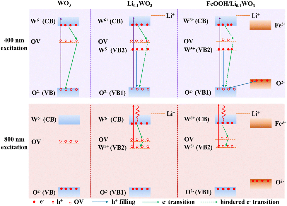 | ||
| Scheme 1 Schematic diagram of hindered photo-carrier recombination in Li0.1WO3 and FeOOH/Li0.1WO3 under 400 nm and 800 nm irradiation. | ||
When considering Li0.1WO3, as described above, the intercalation of lithium atoms leads to the reduction of some W6+ ions to W5+. Consequently, in addition to the intrinsic CB and VB (denoted as VB1 in Li0.1WO3 and FeOOH/Li0.1WO3) of WO3, the partially occupied 5d orbitals of W5+ constitute a new valence band, referred to as VB2 in Scheme 1. This results in a reduced band gap of approximately 0.78 eV.2 Considering that lithium intercalation exerts negligible influence on the intrinsic band gap of WO3, it is reasonable to expect that the positioning of OV states in Li0.1WO3 would closely mirror that in WO3. Accordingly, as illustrated in Scheme 1, VB2 is anticipated to be positioned marginally lower than the OV states. For Li0.1WO3 right after the 400 nm illumination, there should be abundant excited e−/h+ on CB/VB1. However, electrons occupying VB2 are likely to swiftly transfer to VB1 to neutralize h+ (sketched as the blue arrow in Scheme 1 on the Li0.1WO3 panel of 400 nm excitation). This hole filling behavior, which has been observed intensively in semiconductors,24 leads to a reduction in h+ concentration on VB1, impeding the migration of electrons trapped at OVs to VB1 ((sketched as the green dotted arrow in Scheme 1 on the Li0.1WO3 panel of 400 nm excitation)). Consequently, the transition of electrons from the CB to OV is obstructed, and e− remain in the CB for an extended duration, elucidating the observed prevalence of prolonged first-order relaxation processes in Li0.1WO3 as compared to WO3.
Upon the deposition of FeOOH onto Li0.1WO3, while the energy level structure remains largely unaltered, OVs in Li0.1WO3 are partially passivated as evidenced by the aforementioned XPS data analysis. Consequently, the trapping effect of OVs on e− is diminished. Meanwhile, FeOOH possesses an intrinsic band gap of approximately 2.2 eV, which is marginally smaller than that of WO3.33 When integrated with Li0.1WO3, the VB of FeOOH, which is also derived from the 2p orbitals of O2−, is anticipated to be marginally higher in energy than that of Li0.1WO3, as depicted in Scheme 1. In this case, for FeOOH/Li0.1WO3 illuminated by 400 nm photons, in addition to the hole filling from VB2 to VB1 (vertical blue arrow in Scheme 1 on the FeOOH/Li0.1WO3 panel of 400 nm excitation), holes on the VB1 are also neutralized by electrons from the 2p orbitals of O2− in FeOOH (oblique blue arrow in Scheme 1 on the FeOOH/Li0.1WO3 panel of 400 nm excitation). The combined effect of the reduced OV trapping and the enhanced hole filling is expected to decelerate electron relaxation, thereby rationalizing the extended carrier lifetime observed in the FeOOH/Li0.1WO3 composite compared to Li0.1WO3 alone.
Secondly, we discuss the behavior of charge carriers under 800 nm excitation. Given the weak absorbance of WO3 in the NIR region, no effective TR data were obtained for this material. Therefore, our analysis in this section will focus solely on Li0.1WO3 and FeOOH/Li0.1WO3. As previously mentioned, Li0.1WO3 and FeOOH/Li0.1WO3 exhibit two distinct bandgaps, 2.68 eV and 0.78 eV, respectively. Upon 800 nm irradiation, the photon energy of 1.55 eV, being lower than the intrinsic band gap of 2.68 eV, will only excite electrons from VB2, leading to the formation of hot electrons and holes on the CB and VB2. Once cooled to the bottom of the CB, electrons are initially captured by OVs before recombining with holes in VB2 (as depicted by the green arrows in Scheme 1 for the 800 nm excitation of both Li0.1WO3 and FeOOH/Li0.1WO3). As previously discussed, the OVs in FeOOH/Li0.1WO3 may be partially passivated by the FeOOH component. Therefore, in FeOOH/Li0.1WO3, the trapping of electrons is obstructed, resulting in an extended residence time for electrons in the CB relative to Li0.1WO3.
The prolonged electron lifetime should have a positive effect to the PC/PEC efficiencies, which can be interpreted with an example of the photocatalytic process of CH4 and H2O2 reacting to produce CH3OH. This process can be succinctly summarized as follows: Firstly, when the incident light energy hv is not less than the band gap width Eg, electrons in the valence band absorb the light energy and transition to the CB, while simultaneously creating holes in the VB. Secondly, the generated e− and h+ migrate to the semiconductor surface under the influence of the electric field or diffusion; finally, the electrons with reducing power react with H2O2 to form hydroxyl radicals, which then react with CH4 to produce CH3OH. In this process, to achieve a higher catalytic efficiency, it is necessary to ensure that the photo-generated electrons effectively separate from the photo-generated holes without recombination and successfully migrate to the semiconductor surface. In this study, the TR technique directly observes the lifetime of photo-generated electrons. For example, TR experiments observed a longer lifetime of photo-generated electrons in FeOOH/Li0.1WO3, which on one hand proves that they are effectively separated from the photo-generated holes without recombination, and on the other hand, the longer survival time also provides ampler time for the photo-generated electrons to transfer to the semiconductor surface. This is in accordance with the greatly improved photocatalytic efficiency of FeOOH/Li0.1WO3 compared with Li0.1WO3 and WO3 observed previously.3
Except for the elevated photocatalytic efficiency, WO3-based composites have been proved to demonstrate significant enhancements in PEC properties. For instance, AxWO3 (where A represents H+, Na+, K+) not only broadens the optical absorption spectrum to the NIR region but also displays notably enhanced photoelectric anticorrosion capabilities;4 in addition, under simulated sunlight irradiation, the heterostructured WO3/FeOOH photoanode has been observed to deliver a photocurrent density nearly double that of pristine WO3.8 Given the importance of prolonged carrier lifetimes in boosting charge transfer, separation, extraction, and storage efficiencies within sunlight harvesting systems, we propose that the superior PEC performances of these composites may also be partially attributed to the presence of long-lived photo-carriers in them.
Conclusions
In this study, the TR technique was employed to scrutinize the dynamics of photo-carriers within WO3-containing composites, specifically Li0.1WO3 and FeOOH/Li0.1WO3, in comparison to pure WO3. The experimental findings indicate that under 400 nm excitation, the photo-carriers in FeOOH/Li0.1WO3 exhibit a significantly extended lifetime, enduring approximately twofold and tenfold longer than those in Li0.1WO3 and pure WO3, respectively. Furthermore, under 800 nm excitation, the photo-carriers in FeOOH/Li0.1WO3 demonstrate a lifetime nearly four times longer than those in Li0.1WO3. These prolonged lifetimes are posited to enhance the PC/PEC performance, which can be ascribed to the hole filling effect arising from lithium intercalation and the passivation mechanism of OV defects by FeOOH. This investigation not only offers valuable insights for optimizing the PC/PEC performance of WO3-based systems but also introduces innovative perspectives on the underlying mechanisms that may elude traditional investigative approaches.Author contributions
Investigation, data analysis and writing – original draft: H. Z.; DFT calculations: T. J.; XPS measurement and data analysis: M. Z.; sample preparation: H. L.; resources, project administration, and supervision: F. L. All authors discussed the results and contributed to the final manuscript.Data availability
The data that support the findings of this study are available from the corresponding author, H. Z., upon reasonable request.Conflicts of interest
There are no conflicts to declare.Acknowledgements
This work was supported by the Foundation for University Young Teacher by Shanghai Municipal Education Commission under Grant No. ZZ202215003.References
- Y. Yao, D. Sang, L. Zou, Q. Wang and C. Liu, Nanomaterials, 2021, 11, 2136 Search PubMed.
- X. Wu, Y. Li, G. Zhang, H. Chen, J. Li, K. Wang, Y. Pan, Y. Zhao, Y. Sun and Y. Xie, J. Am. Chem. Soc., 2019, 141, 5267–5274 Search PubMed.
- Y. Zeng, X. Luo, F. Li, A. Huang, H. Wu, G. Q. Xu and S. L. Wang, Environ. Sci. Technol., 2021, 55, 7711–7720 Search PubMed.
- Z.-X. Liu, D. Zhou, J.-J. Tian and J.-K. Liu, Adv. Eng. Mater., 2023, 26, 2301003 Search PubMed.
- Z.-F. Huang, J. Song, X. Wang, L. Pan, K. Li, X. Zhang, L. Wang and J.-J. Zou, Nano Energy, 2017, 40, 308–316 Search PubMed.
- K. Pingmuang, J. Chen, W. Kangwansupamonkon, G. G. Wallace, S. Phanichphant and A. Nattestad, Sci. Rep., 2017, 7, 8929 Search PubMed.
- Z. Ni, Q. Wang, Y. Guo, H. Liu and Q. Zhang, Catalysts, 2023, 13, 579 Search PubMed.
- G. Zheng, S. Jiang, M. Cai, F. Zhang and H. Yu, J. Alloy. Compd., 2024, 981, 173637 Search PubMed.
- Y. Li, Y.-K. Peng, L. Hu, J. Zheng, D. Prabhakaran, S. Wu, T. J. Puchtler, M. Li, K.-Y. Wong, R. A. Taylor and S. C. E. Tsang, Nat. Commun., 2019, 10, 4421 Search PubMed.
- D. Grinberg and Y. Paz, Curr. Opin. Green Sustainable, 2023, 41, 100768 Search PubMed.
- X. Wang, M. Sayed, O. Ruzimuradov, J. Zhang, Y. Fan, X. Li, X. Bai and J. Low, Appl. Mater. Today, 2022, 29, 101609 CrossRef.
- E. Mitchell, A. Law and R. Godin, Chem. Commun., 2021, 57, 1550–1567 Search PubMed.
- J. Wei and W. Shen, Colloid. Surface. A, 2022, 643, 128754 Search PubMed.
- J. Wang, L. Jiang, F. Liu, M. Jia, M. Liu, J. Li and Y. Lai, Chem. Eng. J., 2021, 407, 127195 CrossRef CAS.
- W. Sun, M. T. Yeung, A. T. Lech, C.-W. Lin, C. Lee, T. Li, X. Duan, J. Zhou and R. B. Kaner, Nano Lett., 2015, 15, 4834–4838 Search PubMed.
- L. Chen, S. Lam, Q. Zeng, R. Amal and A. Yu, J. Phys. Chem. C, 2012, 116, 11722–11727 Search PubMed.
- S. Chen, T. Liu, M. Chen, M. Ishaq, R. Tang, Z. Zheng, Z. Su, X. Li, X. Qiao, P. Fan and G. Liang, Nano Energy, 2022, 99, 107417 CrossRef CAS.
- I. Grigioni, M. Abdellah, A. Corti, M. V. Dozzi, L. Hammarström and E. Selli, J. Am. Chem. Soc., 2018, 140, 14042–14045 CrossRef CAS PubMed.
- A. Ramzannezhad, P. Gill and A. Bahari, BioNanoMaterials, 2017, 18, 20170008 Search PubMed.
- W. Chen, Q. Xu, Y. S. Hu, L. Q. Mai and Q. Y. Zhu, J. Mater. Chem., 2002, 12, 1926–1929 RSC.
- A. C. Kozen, A. J. Pearse, C.-F. Lin, M. A. Schroeder, M. Noked, S. B. Lee and G. W. Rubloff, J. Phys. Chem. C, 2014, 118, 27749–27753 CrossRef CAS.
- F. Wang, C. Di Valentin and G. Pacchioni, Phys. Rev. B: Condens. Matter Mater. Phys., 2011, 84, 073103 CrossRef.
- X. Lu, K.-h Ye, S. Zhang, J. Zhang, J. Yang, Y. Huang and H. Ji, Chem. Eng. J., 2022, 428, 131027 CrossRef CAS.
- P. Piatkowski, B. Cohen, F. Javier Ramos, M. Di Nunzio, M. K. Nazeeruddin, M. Grätzel, S. Ahmad and A. Douhal, Phys. Chem. Chem. Phys., 2015, 17, 14674–14684 Search PubMed.
- J. S. Manser and P. V. Kamat, Nat. Photonics, 2014, 8, 737–743 Search PubMed.
- Z. Chi, H. Chen, Z. Chen, Q. Zhao, H. Chen and Y. X. Weng, ACS Nano, 2018, 12, 8961–8969 CrossRef CAS PubMed.
- C. C. S. Chan, K. Fan, H. Wang, Z. Huang, D. Novko, K. Yan, J. Xu, W. C. H. Choy, I. Lončarić and K. S. Wong, Adv. Energy Mater., 2021, 11, 2003071 Search PubMed.
- R. Qian, H. Zong, J. Schneider, G. Zhou, T. Zhao, Y. Li, J. Yang, D. W. Bahnemann and J. H. Pan, Catal. Today, 2019, 335, 78–90 Search PubMed.
- P. J. Boruah, R. R. Khanikar and H. Bailung, Plasma Chem. Plasma Process., 2020, 40, 1019–1036 Search PubMed.
- M. Sachs, J. S. Park, E. Pastor, A. Kafizas, A. A. Wilson, L. Francas, S. Gul, M. Ling, C. Blackman, J. Yano, A. Walsh and J. R. Durrant, Chem. Sci., 2019, 10, 5667–5677 Search PubMed.
- W. Wang, A. Janotti and C. G. Van de Walle, J. Mater. Chem. C, 2016, 4, 6641–6648 Search PubMed.
- K. Kato, Y. Uemura, K. Asakura and A. Yamakata, J. Phys. Chem. C, 2022, 126, 9257–9263 Search PubMed.
- F. M. Ali, M. Hmadeh, P. G. O'Brien, D. D. Perovic and G. A. Ozin, ChemNanoMat, 2016, 2, 1047–1054 Search PubMed.
Footnote |
| † Electronic supplementary information (ESI) available: S1: preparation for WO3, Li0.1WO3 and FeOOH/Li0.1WO3; S2: survey XPS spectra of the three samples; S3: transient reflectance measurements; S4: interpretation of the carrier dynamics detected using an 800 nm probe under 400 nm and an 800 nm pump for the TR measurements; S5: analysis of the carrier dynamics using the first and second order mechanisms. See DOI: https://doi.org/10.1039/d4tc01430h |
| This journal is © The Royal Society of Chemistry 2024 |