 Open Access Article
Creative Commons Attribution 3.0 Unported Licence
A review on the transition from conventional to bipolar designs of anode-less all-solid-state batteries
Vikas
Sharma
 *,
Kushal
Singh
and
Krishnamurthy
Narayanan
*
Battery Division HPCL Green R & D Centre Bengaluru, KIADB Industrial Area, Tarabanahalli, Devanagonthi, Bengaluru, Karnataka-562114, India. E-mail: vikas.sharma@hpcl.in; knarayanan@hpcl.in
First published on 17th May 2024
Abstract
Large-scale energy storage technologies are becoming increasingly necessary for the effective use of clean and sustainable energy sources. Solid-state lithium batteries (SSLBs) based on non- or less flammable solid-state electrolytes are gaining popularity owing to their greater safety than regular Li-ion batteries. Additionally, when built using a bipolar architecture, SSLBs can offer significant advantages in terms of battery parameters, i.e., power and energy densities together with the cost. Since the introduction of “rocking chair” batteries in the 1990s, the energy density of lithium-ion batteries has steadily increased. In order to achieve a higher energy density, an anode-free arrangement has been proposed and extensively researched in recent years. This review article briefly discusses the key elements and technologies for bipolar SSLBs, including composite electrodes, bipolar plates, and Li+-conducting SEs. This paper highlights the present problems and difficulties in this developing sector while providing an outline of the recent advancements in anode-free solid-state batteries. Although there are various challenges that need to be addressed, anode-free solid-state batteries can be developed faster using the knowledge gained from solid-state lithium metal batteries and liquid electrolytes. This will indeed assist the existing battery technology to move one step forward towards the development of novel, inexpensive, eco-friendly and high-performance bi-polar anode-less solid-state batteries.
1. Introduction
Effective energy conversion and storage technology using different energy sources, in particular renewable sources, is of great importance considering their various applications. In this aspect, electrochemical secondary batteries have gained significant interest in the past few decades.1–5 Lithium-ion batteries (LIBs) are the popular sources of storage devices because of their properties such as high power input, long cycling life, high power output, and high energy density, which make them potential candidates, and are widely used in devices such as electric vehicles and portable electronics.6–11 However, the limited reserves and escalating cost of Li salts with growing demands have become severe problems. Consequently, the development of alternative energy storage systems has become essential for future requirements. After vigorous investigations, researchers have focused on sodium (Na) batteries due to the abundance of Na resources, comparable performance to LIBs, and cost-effectiveness.12–17 Although sodium has abundant natural resources, its electrochemical performance is not better as compared to Li ion batteries.18–20To date, liquid electrolytes are the most widely used electrolyte materials, but they still suffer from safety problems such as liquid leakage, explosiveness, weak thermal stability, and ignitability.21,22 However, solid electrolytes exhibit superior properties to liquid electrolytes, such as low flammability, high thermal stability, no volatilization and leakage, no risk of explosions and fire, which are more favourable for developing solid-state Li ion batteries with high stability and safety.23–25 Additionally, the battery cell design can be simplified with solid electrolytes since they do not require any additional containment or separator components and deliver better mechanical performance.26–32
Solid-state lithium batteries are predicted to lead the next generation of vehicle power batteries. (Fig. 1).21 Solid-state electrolytes consist of polymer-based electrolytes, and sulfide- and oxide-based inorganic electrolytes, and each type of electrolyte exhibits respective advantages and disadvantages.33–35 One of the major concerns for the practical applications of LIBs using non-aqueous liquid electrolytes is battery safety, which is independent of the competitive ionic conductivity (10 mS cm−1).22 The flammability and thermal instability of organic solvents used in these electrolytes cause serious safety issues, particularly when batteries are overcharged, internally shorted, or exposed to elevated temperatures. In LIBs equipped with graphite anodes above 80 °C, the solid electrolyte interphase (SEI) is unstable and starts dissolving at 120 °C. As a result, lithium in graphite anodes will start reacting with electrolytes and at 135 °C the polyethylene separator will start to melt. With the polyethylene (PE) separator, the temperature beyond 135 °C does not work and cells become shorted. Moreover, the increase in cell temperature leads to the decomposition of cathode materials. If oxygen is evolved from the cathode, the battery will readily catch fire due to the availability of all hygroscopic materials in the vicinity, causing cell explosion. Several ways have been investigated for replacing/changing the electrolyte, which can increase cell safety and stability. Because of their high thermal and chemical stabilities, solid-state electrolytes (SSEs) are considered most promising.23–25,36 Furthermore, SEs have a wider electrochemical potential window (∼8 V against Li/Li+) than that of liquid organic electrolytes (∼4.2 V vs. Li/Li+), allowing them to mix with high-voltage cathodes and provide high specific energy to batteries.36 SEs also make battery construction easier by eliminating the requirement of separators to avoid the physical contact between the cathode and the anode. Solid-state LIBs, however, are currently under development, owing to the scarcity of solid electrolytes with high lithium ion conductivity and low interfacial compatibility between the electrodes and the electrolyte.23,24,26–32 Li-ion conducting SEs can be generally classified into three categories, namely, (1) inorganic electrolytes, (2) organic electrolytes, and (3) composites. For any feasible design of solid-state LIBs, the material to be employed as an electrolyte should have a conductivity of at least 1 mS cm−1, and a conductivity beyond that will be appreciable.
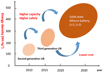 | ||
| Fig. 1 Energy density growth trend of lithium batteries in the future (Advanced Energy Materials, 8(11), 1702657) (reproduced with permission from ref. 21). | ||
A solid-state battery with lithium is depicted in Fig. 2. The Li ions migrate during the charging and discharging processes, respectively, as indicated by the curved arrows. The external circuit's load is driven by the electrons produced via chemical redox reactions. The set of cathode and anode materials and their corresponding suitable electrolytes are also mentioned in Fig. 2, marked with matching colors (in the web version).
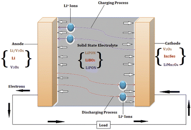 | ||
| Fig. 2 Schematic of a representative lithium-based solid-state battery, showing the direction of ion movement and some of the possible anode, electrolyte, and cathode combinations (reproduced with permission from ref. 37). | ||
The use of SSE advancements in complete cell structures is required to demonstrate their applicability and validate the claimed advantages. Understanding the constraints of materials, processing power, and most significantly, cell form factor, is necessary for the integration of such structures. There are various approaches to integrate SSEs into whole-cell topologies. The primary potential cell design topologies for all SSE families are shown in Fig. 3.
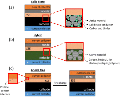 | ||
| Fig. 3 Illustration of main cell architectures utilized in solid-state battery research to date: (a) all-solid-state configuration using a solid-state cathode interfaced with a solid electrolyte and a high-energy density solid anode; (b) a hybrid approach using a liquid or polymer-based cathode interfaced with a solid electrolyte and a high–energy density anode; and (c) anode-free design in which the cell is constructed with only a cathode and a separator while the metal anode is formed upon first charge. (Reproduced with permission from ref. 38). | ||
A hybrid design naturally develops in some SSE systems as a potential fix for rate capability and high-temperature processing compatibility problems. Some SSEs provide this potential path for integration, as schematically displayed in Fig. 3. Due to their brittleness, oxides are difficult to mechanically adhere and provide stable interfaces with cathode components; however, a hybrid system is made viable by using another ionic conductor in the liquid or polymer phase, such as a gel.
The anode in the majority of research investigations is employed as a means for extending life by using extra Li metal.39 The existing literature lacks the discussion on the fact that extensive use of Li–metal reduces the volumetric energy density of the batteries. Additionally, excessive Li metal consumption raises safety concerns, which include potential fire and explosions. This inspired the researchers to think in a novel dimension to use less Li–metal anodes.
During charging and discharging of an anode-free battery, Li–metal plates and strips are located on the exposed current collector (CC). Since the negative-to-positive areal capacity ratio (N/P) of the anode-free battery is almost zero, it is considered as a special type of Li–metal battery. The anode-free design minimizes the volume in the anode side and produces a higher energy density (Fig. 4b) than that of the conventional Li–metal battery (Fig. 4a). However, the dendritic Li plating and low coulombic efficiency of the anode-free batteries result in poor cycling stability.40
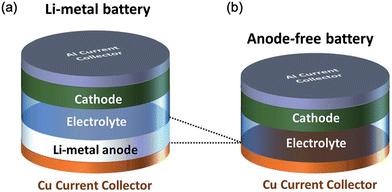 | ||
| Fig. 4 (a) Li–metal battery and (b) anode-free battery. (Reproduced with permission from ref. 41). | ||
Fig. 5 compares the alternative cell designs in terms of notional GED (gravimetric energy density) and VED (volumetric energy density), assuming that similar active materials are used in liquid electrolyte– and SSE-based cells. This assumption necessitates the liquid and solid electrolyte systems having equal electrochemical stability windows. Reducing the electrochemical stability window reduces the active material utilization based on its usual intercalation profile. As a result, both specific capacity and cell voltage fall, resulting in lower GED and VED. As a result, the ranking of GED and VED of various cell ideas in Fig. 5 is only relevant if sufficiently stable electrolytes are used, highlighting the critical importance of the electrochemical stability window in the development of SSB and anode-less solid-state batteries (ALSSBs), as discussed further below.42
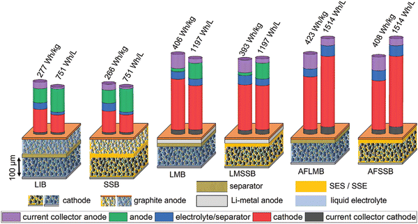 | ||
| Fig. 5 Schematics of cell configurations, stack weight and volume distribution, and estimated energy density for conventional Li-ion batteries and solid-state batteries with intercalation-type electrodes, Li–metal anode, and anode-free configuration. (Reproduced with permission from ref. 42). | ||
Low coulombic efficiency (CE) and lithium dendrite formation were identified as the primary issues faced by anode-free batteries in this review and explored in the first section. The anode-free battery has hurdles due to interfacial concerns such as heterogeneous Li plating, interfacial parasitic reactivity, and dead lithium. The modification of the surface chemistry is, therefore, a promising strategy for improving the electrochemical performance of anode-less batteries, which has received widespread attention and is also included in this review. Compared to liquid electrolytes, all-solid-state batteries without anodes are challenged by the more complex interface problems described in the previous section. In this context, it becomes necessary to explore the foundations of bipolar battery construction, which will be discussed in a later section.
2. Types of solid electrolytes in Li-ion solid-state batteries
Rechargeable lithium-ion batteries (LIBs) have been crucial to the fabrication and quick adoption of many portable electronic devices. Recently, solid-state Li batteries (SSLBs), whose electrolytes are composed of solid materials that can conduct Li+, have become important. As the issues pertaining to SSEs, which hinder their commercialization, have been already discussed in the Introduction section, only a summary of those issues is presented in Fig. 6. Each form of SSE has its own set of issues based on its composition, which may be loosely grouped into three categories: inorganic ceramic SSEs, polymer SSEs, and ceramic–polymer hybrid SSEs (Fig. 7 and Table 1).43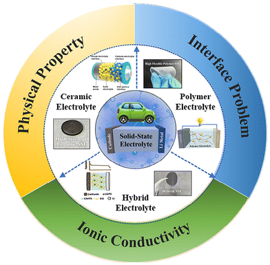 | ||
| Fig. 6 Schematic of the main types and the direction of improvement of solid-state electrolytes. (Reproduced with permission from ref. 43). | ||
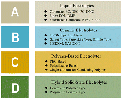 | ||
| Fig. 7 Summary of common electrolyte system types and examples. (Reproduced with permission from ref. 43). | ||
| Types of SSE | Ionic conductivity | Interfacial compatibility | Electrochemical stability | Mechanical strength | Price |
|---|---|---|---|---|---|
| LE | Excellent | High | Medium | Low | Cheap |
| CE | High | Low | Medium | Excellent | Cheap |
| PBE | Low | Excellent | High | Medium | Expensive |
| HSE | High | High | High | High | Expensive |
Among all the electrolytes illustrated in Fig. 7, it has become clear with the advancement of knowledge that the hybrid solid-state electrolytes display good electrochemical performance, but they are expensive than the conventional ceramic electrolytes. Most importantly, hybrid SSEs are considered safer than the liquid electrolytes because of their superior thermal and electrochemical stabilities. A few other astonishing properties including high ionic conductivity, high stability, and low interfacial resistance make them even more interesting. Hybrid SSEs rationally combining the properties of two or more SSEs are promising candidates for establishing a suitable solid-state lithium battery.44–47 The most common hybrid electrolyte consists of a soft polymer electrolyte and a rigid inorganic SSE. The presence of the rigid part provides high ionic conductivity at room temperature and the soft part solves the issues pertaining to wettability at the interface with electrodes.45,48 Another category of hybrid electrolytes comprises multilayer-structured hybrid electrolytes, in which a ceramic SSE layer provides Li+ ion conductivity and a constituent separator with a soft polymer electrolyte outer layer is enclosed to tune the interface against electrodes.49–51 Sometimes, the soft polymer electrolyte is replaced with a trace amount of liquid electrolytes, which are spread on the SSE surface to improve the ionic conduction between the rigid oxide SSEs and the respective electrodes. This kind of configuration is referred to as liquid–oxide hybrid electrolyte.49
3. Structural design of solid-state batteries
Before going into the details of Bi-polar solid-state batteries, it is important to understand the basic framework of solid-state batteries. Different forms of integrated battery structures that are capable of effectively resolving a range of interface issues have developed from the overall solid-state battery design. The enlargement of the electrochemical stability window depends on the creation of the optimum electrode–solid electrolyte contact. The most widely used design in interface engineering so far is the multilayer electrolyte concept. Fu et al.52 proposed the modification of the electrode–electrolyte interface by embedding a Li–Al alloy layer as a wetting layer. According to the study, the garnet SSE material can be completely coated with an Al-alloyed Li metal. According to that comparison, garnet/Li in direct contact has an interface impedance of ∼950 cm2, which decreases to ∼75 cm2 after surface modification. Such improvement was greater than an order of magnitude. The most popular and efficient method to increase the mechanical compatibility and lower interface resistance is thought to be the addition of an intermediate layer between the solid electrolyte and the lithium metal. The documented surface treatment layers to date include a thin coating of Li–M alloy, oxides, or amorphous Si. Additionally, the electrode/electrolyte interface was tackled by Professor Wang's team from the South China University of Technology using a novel approach. The cathode electrode material is immediately covered with the SSE suspension.53 Meanwhile, the suspension with the solvent can penetrate into the pores of the cathode electrode material, which perfectly solves the contact problem between the electrode and the electrolyte (Fig. 8).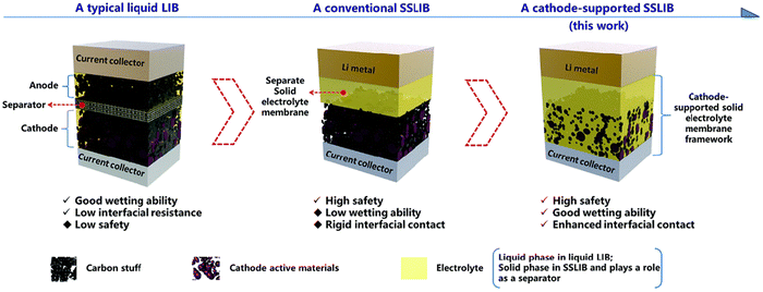 | ||
| Fig. 8 Schematic of the novel cathode-supported SSLIB in comparison with a conventional rigid SSLIB and a typical liquid LIB. (Reproduced with permission from ref. 43). | ||
Based on their settings and electrode/electrolyte materials, various types of solid-state electrolytes have been used. As a result, solid-state electrolytes can be generally divided into two categories: bulk and thin-film electrolytes. It is primarily the thickness of the electrolyte that makes the difference. Bulk solid-state electrolytes typically have a thickness of several hundred micrometers to several microns, whereas thin-film solid-state electrolytes have a thickness of several hundred nanometers to several microns. Bulk solid-state electrolytes are typically manufactured using methods including mechanical milling, sintering and compaction, annealing, and heat treatment. However, thin-film solid-state electrolytes are made by various methods such as solution casting, atomic Layer deposition, pulsed laser deposition, spark plasma sintering, and CVD. A novel concept of a cathode-supported solid-state electrolyte was established with a facile tape casting technique.54 The as-prepared cathode-supported solid electrolyte membrane significantly improves the interfacial contact between the cathode and the solid electrolyte by enhancing the wettability of solid electrolytes onto the cathode and reinforcing interfacial adhesion. SSLBs directly fabricated with the as-prepared cathode-supported solid electrolyte membrane and a metal lithium anode deliver superior battery performances over the conventional SSLBs.54,55 The cost of these batteries is still higher, which also does not support the ongoing higher price tag of electric vehicles across the globe. Moreover, the process to make a solid-state battery is complex. Materials for this technology are scarce and very expensive. Above that, there is no standardized material used in the manufacturing process, and moreover, no standardized process for fabrication.56 This makes it extremely difficult for their mass production. Various auto companies such as GM, Toyota, and Mercedes have heavily invested in solid-state battery technology, in hopes of increasing range and charging capabilities.57
4. Thin-film solid-state batteries
Thin-film battery systems, particularly Li-ion systems, have historically been used in zero-emission automobiles, aerospace, military facilities, and medical apparatus. The most widely studied solid-state batteries are thin-film batteries with Li electrolytes produced by Hitachi Co., Japan. The battery was called the “all-solid-state thin-film battery” and incorporated a TiS2 cathode, a metallic lithium anode, and a Li3.6 Si0.6P0.4O4 thin-film electrolyte prepared by the RF sputtering technique.4.1. Thin-film solid-state battery electrodes
Electrodes of thin-film batteries play an important role in the proper performance of the battery; hence, it is essential to choose the right electrode materials for solid-state batteries, as shown in Fig. 9. There are a few necessary considerations for choosing the electrode material such as: (a) the ability of the material to support lithiation and de-lithiation, particularly if the battery being designed is Li-based, (b) the theoretical energy storage capacity and (c) a significant contact surface area with the electrolyte for the electrochemical reactions to occur effectively.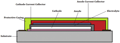 | ||
| Fig. 9 Cross-section of a thin-film solid-state battery showing different components. The substrate acts as a support on which the thin film is usually deposited. (Reproduced with permission form ref. 37). | ||
Materials with strong Li storing capabilities are frequently preferred for anodes. Al, Sn, and Si alloys are ideal options because they have reversible electrochemical interactions with lithium and have good specific capacity, e.g., 4200 mA h g−1 for a LiSi alloy. Among several types of high-energy-density electrochemical systems such as advanced LIBs, metal–air batteries, and fuel cells currently under development, SSLBs would be the most promising technology for large-scale storage and generation systems represent facility where security issues are of vital importance. In addition, the non-polar architecture of SSLBs exhibit significant performance and battery cost-effectiveness compared to traditional LIBs. There are a series of issues associated with thin-film batteries pertaining to the electrolyte, interface and cathode. The two key issues are solid electrolytes with high ionic conductivity and solid interfaces. For the preparation of thin-film battery electrodes, sophisticated and costly techniques are required, such as magnetron sputtering (MS), pulsed laser deposition (PLD), atomic layer deposition (ALD) and vacuum evaporation.58,59 The fabrication and utilization of thin-film batteries is the current hot research topic due to its good power density, which can be significantly increased by the design of 3-D structures. Compared to the bulk-type solid-state batteries, thin-film batteries exhibit higher charge/discharge rates due to the improved contact between the thin-film electrodes and SSEs. Some of the most promising applications of thin-film batteries include: (1) wearable devices, (2) internet-of-things devices, (3) medical implants, (4) military and aerospace applications, (5) energy-harvesting devices, and (6) smart cards.60,61 Thin film battery chemistry is important to understand the role of thickness in energy storage. This can be helpful in developing bipolar electrodes with lesser thickness and mass loading to achieve high performance.
5. Bipolar LIBs
The concept of a “bipolar battery” involves the integration of bipolar electrodes into a battery module. In theory, this technology can be used to power batteries with varying chemical compositions. However, among different types of bipolar batteries, only the lead–acid battery module has reached the commercial production phase. LIBs with organic electrolytes process a higher voltage output than that of the lithium aluminum batteries (LABs) and Ni–metal hydroxide batteries (NMHBs) possessing an aqueous electrolyte. When bipolar LIBs are combined with the bipolar electrodes (BEs), it will be more competitive in the application of electric and hybrid electric vehicles. Electric transportation requires battery packs with a working voltage of 300–500 V.62 Such high-voltage battery packs require several hundreds of cells to be connected in series. In this case, the role of BEs becomes critical in order to use less wires for cell series connection and makes the process/design less cumbersome. Alongside, the combination of high voltage and high current delivery rate also enables fast acceleration and charging behaviors.In the electrolyte arena, a recent advancement has been made in the direction of developing and utilizing bipolar electrodes. Toyota created a bipolar solid-state cell stack prototype and demonstrated that four layers of single unit cells could be stacked to achieve a maximum voltage of 16.26 V.9 Gambe et al.32 also constructed a bipolar stack based on a quasi-solid-state electrolyte and experimentally showed a stack voltage of up to 12 V. Ito et al.40 built a parallel solid-state cell stack with a capacity of 1 A h by stacking three double-coated unit cells. In parallel stacking, instead of series stacking in bipolar plates (BP), the electrical current flows in-plane along the current collectors (CC) to the external tabs. In the case of series stacking, the electrical current flows from one unit cell to the near-adjacent unit cell through the BP.
5.1. General architecture of Bipolar LIBs
For high capacity application, the battery cell is made up of numerous unit cells associated in arrangement and/or parallel to meet the control and vitality prerequisite. Tesla EV 100 kW h battery framework contains ∼8000 LIB cells. On the premise of how unit cells are electrically associated with each other in one module, the battery structures may be partitioned into two categories: monopolar and bipolar (Fig. 10).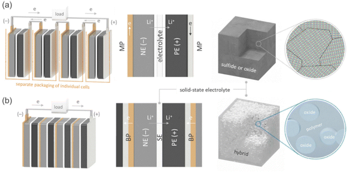 | ||
| Fig. 10 Schematic diagrams of (a) the monopolar design of current LIBs with liquid electrolytes and (b) bipolar design of SSLBs equipped with SEs. The Li+ and electron pathways during discharge are also indicated. (Reproduced with permission from ref. 63). | ||
For the construction of SSLBs, it requires an electrically conductive BP (Current collector), which works as both an electrical interconnection and partition between the adjacent cells.30,34,36,43,44 To avoid internal short-circuiting, the BP should be electrically insulated around its edges.42–44 Hence, for the successful operation of batteries; (a) BP must be chemically and electrochemically stable under the prescribed operating conditions (Fig. 12), (b) it should be electronically conductive for current flow between the cells without significant ohmic losses, (c) it should be capable of maintaining good adhesion to the electrodes with high mechanical stability against possible expansion and contraction during charge–discharge cycling42–44 and (d) it should show overcharge tolerance because in the presence of performance variation in the constituent cells, relatively poor performing cells can have higher states of charge at a given time than the other cells.40,41
5.2. Working principal of bipolar batteries
The basic concept of a bipolar battery is as follows: the negative electrode of one cell and the positive electrode of another cell are much closely placed together (back-to-back). The cathode and the anode are coated on the substrate, which serves as a seal between the adjacent cells. The electrical current flows between the cells directly through the electrodes and the thin conductive substrate.64 In this case, intermediate jumpers between adjacent cells are not necessary. The cells are housed in a common container, and one or more containers are joined together to form battery modules.65 The schematic of a bipolar electrode module is provided in Fig. 10.Bipolar electrodes offer various advantages such as simplifying battery components, boosting power/energy density, and lowering manufacturing cost. The bipolar electrodes find applications in various emerging fields such as wearable technologies, combination with solid-state electrolytes, and recyclable batteries. Moreover, bipolar electrodes have been successfully applied in lead–acid batteries and also nickel metal hydride batteries, expanding their working and application regimes.66,67 However, there are a few shortcomings associated with bipolar electrodes regarding the issues of sealing and serious substrate corrosion that leads to battery failure after few cycles, which need to be considered as factors or scope for improvements in their composition and structure.66
6. Recent advances in the design and electrochemical performance of bipolar-type solid-state lithium batteries
By obstructing the flow of ions between adjacent cells, the non-fluidic feature of SSEs makes it possible to create a bipolar design. Multiple cell stacking within a single package has proven to be quite difficult; relatively few papers on multiple cell stacking within a single package have been published. The stacking methodologies for bipolar SSLBs based on writing are classified into (i) the cover of free-standing SSE sheets and (ii) the printing of SSE slurries. The primary procedure includes the successive cover of unsupported SSE sheets and electrocoated BPs, both of which have adequate mechanical strength. The other procedure included layer by layer printing (coating) of SSE slurries (inks) on electrode-coated BPs which serves as a mechanical back. Then another unit cell is kept above the printed one. In this section, the progress and the technical advancements that took place in the area of the development of bi-polar SSLBs are taken into consideration and discussed elaborately. The major focus is kept on SSEs and their integration with bipolar architectures and how much performance improvement is observed with this combination.51,52Fig. 11 shows the fabricating process of a pouch-type solid-state bipolar battery that is interfacially wetted with an ionogel. The bipolar anode was initially made by coating the LMO composite cathode and the LTO composite anode on both sides of the same aluminum thwart current collector.53–55 An ionogel antecedent arrangement was at that point splashed onto the surfaces of the LMO composite cathode, LLZO–LTO/LMO bipolar anode, and LLZO–LTO bilayers, individually. Along these lines, the impregnated anodes were kept at room temperature for 2 h in situ gelation. Later, the ionogel presented an LMO composite cathode and an LLZO–LTO/LMO bipolar terminal, and LLZO–LTO double layers were stacked and sealed into a pouch cell.
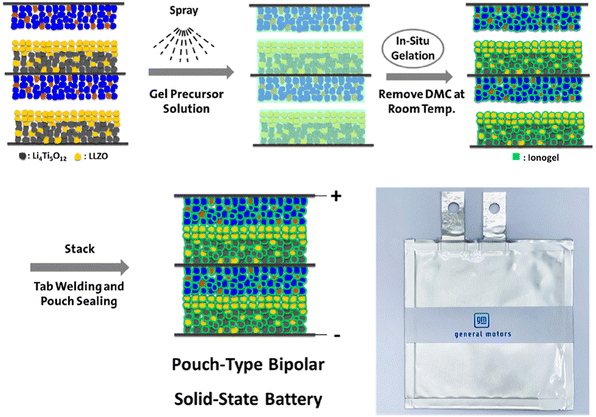 | ||
| Fig. 11 Schematic illustration of the fabrication process of the pouch-type LMO/LLZO–LTO bipolar solid-state battery interfacially wetted with the ionogel. (Reproduced with permission from ref. 68). | ||
Fig. 12a shows the stainless-steel triple stack with an area-oversized current collector. The Simple bipolar setup leads to failure even prior to cell assembly during open-circuit voltage (OCV), as demonstrated in Fig. 12b. Initially, the three-cell connection indicates an OCV of approximately 7.8 V (single cell OCV of 2.3 to 2.7 V) under OCV conditions. However, after approximately 0.6 h, the OCV decreases rapidly by 2.6 V (red arrow in Fig. 12a, which corresponds to a single-cell voltage). However, the OCV is failure-free at 20 °C. At 60 °C, the molten LiTFSi/PEO can form a short circuit between two neighboring cells, as shown in Fig. 12b. Consequently, the two short-circuited cells act as one cell and result in a voltage decay. In addition, the bipolar stack achieves failure-free charge–discharge cycling performance (as shown in the paper45). This similar performance indicates that the design is sufficient.
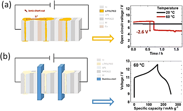 | ||
| Fig. 12 Connection of molten LiTFSI/PEO can explain the short circuit via the detrimental Li ion connection between the cells. OCV is given as a function of time at 20 and 60 °C. Already after ≈0.6 h at 60 °C, the OCV decreases by 2.6 V (this values corresponds to the OCV of a single cell), which points to an ionic shortcut between two cells, while the OCV remains constant at 20 °C. (a) Triple stack with an area-oversized current collector (stainless steel). (b) Setup revealing failure-free galvanostatic charge/discharge performing similar to the single cell. (Reproduced with permission from ref. 69). | ||
6.1. Lamination of free-standing solid electrolytes for the fabrication of bipolar-type solid-state Li batteries
From many available SSE materials, oxide-based SSE garnet-, perovskite-, and NASICON-type structures show acceptable chemical and structural stability under dry as well as humid conditions at the operating temperature. High-temperature sintering is necessary to produce SSE sheets with lower resistance. Furthermore, a large cell resistance results from any inadequate contact between the SSE sheet and the electrode. In order to reduce interfacial resistance, various methods have been investigated, such as the use of soft interlayers, better known as “buffers” and improved co-sintering techniques to create monolithic bi-layered electrode-SSE structures. Zhang et al. fabricated a bipolar SSLB with a sintered LAGPSE pellet. Because of the electrochemical instability of LAGP with metallic Li, an interlayer comprising PEO–Li2S–P2S5–P2O5 was spin-coated onto the NE side of the pellet.70 In addition, PEO–LiClO4 was incorporated into the porous PE to form three-dimensional Li+ conduction pathways in the composite electrode structure. A two-cell bipolar stack, [Al|(+)LiFePO4|SE|Li(−)|],71 is schematically shown in Fig. 13.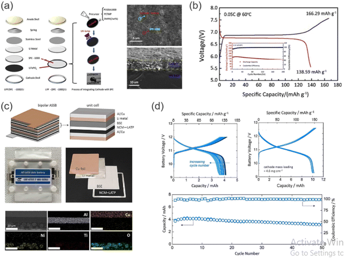 | ||
| Fig. 13 (a) Schematic diagram of the assembling and preparation processes of SSLBs with PEGDA-based SE, and surface/cross-sectional SEM images for the integrated LiFePO4–SE electrode. (b) First charge–discharge profiles for a two-cell bipolar SSLB and cycling performance of monopolar cells at 60 °C. (c) Structural representation and photographs of a multi-layered, bipolar-type SSLB constructed with a hybrid SE (Li0.29La0.57TiO3–PEO) and battery components. Cross-sectional SEM image and corresponding EDS results of LiNi0.6Co0.2Mn0.2O2 PE on the Al/Cu cladded Bipolar Plate. (d) Charge–discharge curves and cycling performance of bipolar-type SSLBs based on a hybrid SE measured at 60 °C. (Reproduced with permission from ref. 63). | ||
Even though sulfide-based SSEs suffer from various chemical basic insecurities against dampness, they are much considered due to their advantage over oxide-based SEs. Sulfide-based SEs appear tall in the case of Li+ conductivity, and even in a few cases, it appears that the conductivity matches the fluid electrolyte. A straightforward cold squeezing handle can actuate contact between inflexible cathode materials and SSEs, leading to the arrangement of the thickly stuffed interface. In free-standing, sulfide-based SSE sheets strengthened with a non-woven polymer framework, a lean Li3PS4 SSE sheet (thickness ∼70 μm) was arranged by coating of the SSE slurry onto the nickel thwart. After coating, the ensuing cold squeezing can be done onto a polyparaphenylene terephthalamide (PPTA) substrate, which serves as a mechanically compliant platform (Fig. 14).
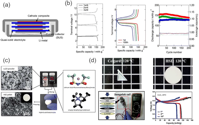 | ||
| Fig. 14 (a) Coin-type bipolar SSLB constructed by stacking the unit cells with SUS BPs. (b) Galvanostatic charge–discharge profiles for one-, two- and three-cell stacked bipolar SSLBs with quasi-SE, and cycle performances of a two-cell stacked bipolar SSLB at different C-rates. Adapted from ref. 37 (CC BY). (c) Schematic illustration of the preparation of hybrid SEs comprising LLZO, Py14TFSI, and LiTFSI. (d) Photographs of the hybrid SE after a thermal shrinkage test (120 °C), and the electrochemical performance of a two-cell bipolar battery with an LLZO–IL-based electrolyte measured at 25 °C. (Reproduced with permission from ref. 72). | ||
Bipolar electrodes work perfectly with the solid-state electrolyte and their unique combination promises low cost and high energy and power densities for solid-state batteries. Due to the sealing process–free attribute, it leads to a simple and compact battery configuration, thus offering a lower manufacturing cost. The noninflammable characteristic of solid-state electrolytes further enhances thermal abuse resistance.66
6.2. Fabrication and characterization of printed bipolar all-solid-state Li–S batteries (ASSLSBs)
On top of the unit cell of the ASSLSB, a stepwise printing process was conducted with UV curing assistance to fabricate an ASSLSB bipolar (Fig. 15a). A single current collector (SUS foil) was employed as a common point of contact between the unit cells. From the cross-section SEM image obtained, it was evident that the three unit cells had been connected in series without any delamination or structural cracks. Apart from the in-series connection, a printed bipolar with an inplane connection was also fabricated (Fig. 15a and b). The stepwise fabrication process of a printed bipolar ASSLSB is outlined in Fig. 15a.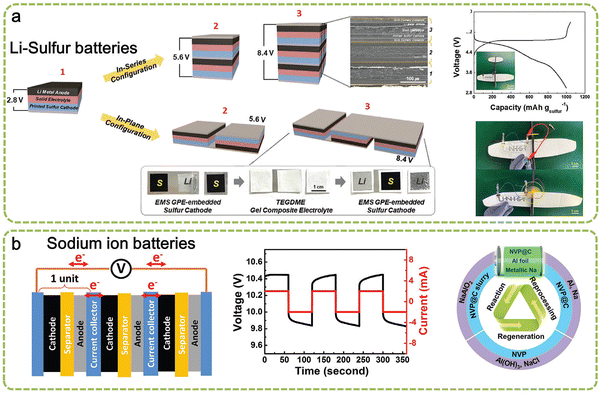 | ||
| Fig. 15 Fabrication and characterization of the printed bipolar ASSLSBs. (a) Schematic representation depicting the fabrication procedure of the printed bipolar ASSLSBs, along with the SEM image (in-series configuration) and photographs (in-plane configurations). (b) Charge/discharge profiles of the printed bipolar ASSLSBs during the 1st cycle (at a charge/discharge current density of 0.1C/0.1C) as a function of cell number. (Reproduced with permission from ref. 73). | ||
Authors have manufactured a UNIST letter on a bipolar (two cells associated in series) ASSLSB on the curvilinear surface of a toy airplane through a UV curing-assisted stepwise printing handle (inset of Fig. 16a). Typical charge/discharge profiles at charge/discharge currents of 0.1C/0.1C are shown in Fig. 16a. The bipolar ASSLSB fueled a light-emitting diode (driven) light and worked a propeller introduced on the toy airplane (Fig. 16b), which illustrates its potential application as an unused sort of solid coordinate control source. In this work, the printed bipolar ASSLSB (two cells associated in series) was mechanically collapsed beneath different mishappening modes (Fig. 16c). The printed bipolar ASSLSB fueled a LED-driven light beneath seriously collapsed states. Interestingly, no obvious alteration in the release capacity was observed amid the collapsing tests.73,74 The safety test for the printed bipolar plate–based pouch cell powering LEDs is shown in Fig. 16d.
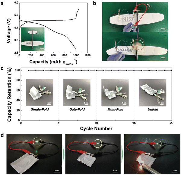 | ||
| Fig. 16 Application of the printed bipolar ASSLSBs. (a) Charge/discharge profiles (at a charge/discharge current density of 0.1C/0.1C) of the “UNIST” letter-shaped bipolar (2 cells connected in series) ASSLSB directly fabricated on the curvilinear surface of a toy aircraft. (b) Photographs showing the operation (LED lamp and propeller of the toy craft) of the printed bipolar ASSLSB. (c) Discharge capacity retention of the printed bipolar ASSLSB in various folding modes. (d) Safety test of the printed bipolar ASSLSB (3 cells connected in series). It stably powered a LED lamp even after being vertically cut in half and exposed to flame. (Reproduced with permission from ref. 73). | ||
The development of bipolar batteries faces some technical challenges such as the internal short-circuits, corrosion sensitivity of the bipolar plates, and unreliable cell stacking.75 In order to realize bipolar batteries, a series of effective strategies are proposed: (i) developing SEs with a high Li+ conductivity and wide electrochemical windows and (ii) a stable conformal interface between SEs and active electrodes can be built. Bipolar battery construction demands electrically conductive bipolar plates as current collectors, which may be suitably provided with edge electrical insulation to prevent internal short-circuiting.66
The anode-free batteries, particularly Li metal–based, have advantages in terms of the highest retrievable gravimetric/volumetric energy densities, facile process of the anode coating and reduced maintenance and production costs of cells.76,77 However, there are issues pertaining to the interfacial contact resistance, curtailed ion pathway and dead lithium formation, which can lead to unsatisfactory cation utilization upon repetitive cycling, and thus, affect the performance badly. Some key strategies and prospective improvement suggestions are listed below for achieving high-performance anode-less batteries:61
(1) An improved SEI layer in terms of mechanical strength and flexibility is responsible for efficient ion influxes. The commercial electrolyte does not meet the requirements; therefore, the formulations with novel salts, solvents, and additives were continuously tried. However, most approaches are concentrated around “Edisonian”-type optimization.78 Additionally, high costs of the novel electrolytes hamper their widespread applications. Hence, the appropriate choice should rely on the low-cost and readily available species for industrial formulations.79
(2) The lattice mismatch of copper with the Li foil could lead to the formation of dead lithium. Even substrate modification cannot yield the close-to-unit CE for the plating process. For this, a Li supplementary strategy involving the introduction of a pre-lithiation agent from the cathode or Li-rich substrate would provide extra cyclable cations and enhance the reversibility.76,80
(3) With regard to characterization, there are possibilities of catastrophic damage to the structure of electrodes due to sensitive Li deposits or other metastable phases contained in anode-free Li ion batteries. Thus, it is hard to detect these signals with the conventional characterization methods. Thus, it is expected to develop the characterization method that could be implemented under the coupled multi-physical fields.76,81
(4) For practical applications, the anode-free batteries suffer from insufficient Li-ion utilization and limited cycle life. As a result, the construction of the anode-less LMB models with balanced energy density and cycle endurance would be the practical choice.41,42,76
7. Interfacial chemistry in solid-state anode-free solid-state batteries
The main problems encountered in the anode-less solid-state battery are the low capacitance and potential required for dendritic Li plating.82 The interactions between the electrolyte and the central counter electrode (CCE) in the electrolyte phase of a solid-state battery become even more complicated to understand. Unlike liquid electrolytes, the capacitance of the electrolyte to the CCE is low, thus increasing the likelihood of dendritic Li plating. Alongside, in order to address the potential mechanical failure of solid-state batteries due to volume fluctuation, the design of a carbon copy (CC) for anode-free batteries has become a challenging task.83 Samsung had announced in 2020 regarding the production of solid-state anode-free battery, which became quite popular and attracted considerable attention. This battery was assembled with a Li6P5Cl SSE and a sliver carbon composite was incorporated into the as-designed CC. The CC was designed with a carbon black ion conductor and Ag particles acting as nucleation seeds. Plating was used to initiate an alloying reaction, which was followed by the deposition of Li under the already deposited carbon black layer. The sliver–carbon-modified CC was able to cycle the anode-free cell >1000 times, with a CE > 99.8%. The pressure applied was ∼2 MPa in order to have proper connects, which also showed a near-stable performance. In 2021, Samsung reported another configuration equipped with an anode-free solid-state electrolyte, in which bare Cu–C was exposed via lamination and heat treatment at a temperature of 700 °C in an argon atmosphere. The laminated Cu–C was placed on the garnet pellet. As the garnet and the Cu–C were in close contact, only a pressure of 4 MPa was applied.84 The battery was operated at a temperature of ∼60 °C. To date, the design of an anode-less solid-state battery without any additional artificial SEI and at room temperature and pressure has been a great challenge. An artificial SEI layer composed of a polymer with a near-similar texture may facilitate the operation of an inorganic solid-state electrolyte-based anode-free battery without additional pressure (Table 2). Nevertheless, room-temperature operation remains a challenge for solid-state anode-free batteries.85| Artificial SEI | Coulombic efficiency (%) | Cycling stability | Current density | Ref. |
|---|---|---|---|---|
| Al2O3 | 98 | 250 cycles | 3 mA cm2 | 86 |
| SiOx | 99.3 | 200 cycles | 2 mA cm2 | 87 |
| Graphene oxide | 98 | 50 cycles | 0.5 mA cm2 | 88 |
| PEO | 98.6 | 200 cycles | 0.2C | 89 |
| garnet@PVDF | 97.6 | 30 cycles | 0.2 mA cm2 | 90 |
| Ag@polydopamine and graphene oxide | 98.6 | 60 cycles | 0.5 mA cm2 | 91 |
| Al2O3@PAN | 97 | 82 cycles | 0.2 mA cm2 | 92 |
8. Conclusions and perspectives of bipolar-type anode-free Li-ion SSBs
A summary of the fundamentals of the architecture of the bipolar battery along with its benefits and technical hurdles are discussed. The most recent developments in the design and production of bipolar SSLBs are elaborately communicated. Regarding bipolar SSLBs, the focus is on their designs and electrochemical performance, and the strategies toward bipolar cell configuration include electrode materials, substrate materials and electrolyte materials, as shown in Fig. 17. Moreover, architectures and electrochemical performance of bipolar SSLBs reported in the literature are summarized in Table 3. The SSLBs offers a basic solution, which can address the safety concerns with the existing LIBs. With a view to develop high-energy and high-power SSLBs, particular attention should be paid to the following areas: (a) new advanced SSE materials should be found with a high Li+ conductivity and/or to optimize their chemical structures, (b) the electrodes should coordinate coherently with the SSE and active materials, (c) the trio, i.e., electrodes, SSE and active materials, should form a continuous network for Li+ and electron flow, (d) the lithium ion movement that can help in making further improvements in the connectivity of internal components should be elucidated, (e) tougher BP materials sustaining corrosion under altered conditions should be developed and stabilized, (f) new designs should be explored, e.g., using two layers of BP materials such as “clad metal” that can be equally good as the BP material because it inherits exceptional qualities from different types of metals and (g) lastly, modelling and simulations should be performed and extensively used in order to create designs for batteries as well as internal components that can store higher energy and work well for longer operations. | ||
| Fig. 17 Summary of the strategies toward bipolar cell configuration, including electrode materials, substrate materials, electrolyte materials; reproduced with permission from ref. 93. | ||
| SE type | SE constituent | No. of cell [V] | Bipolar SSB | Ref. |
|---|---|---|---|---|
| Polymer | PEGDA–PEGDMA–LiTFSI | 2/5.6–7.6 | ∼136 mA h g−1 (0.5C-rate) | 94 |
| Polymer | PEGDA–LiTFSI | 2/5.5–7.5 | ∼138 mA h g−1 (0.05C-rate) | 95 |
| Polymer | PEO–LiTFSI + PVDF + Al2O3 | 3/9.12 | NA | 55 |
| Sulfide | Li3PS4 | 2/2.0–6.4 | ∼83 mA h g−1 (14 mA g−1) | 96 |
| Oxide | LAGP | 2/5.6–7.5 | ∼145 mA h g−1 (0.1C-rate) | 70 |
| Hybrid | Lithiated Nafion + sulfolane–diglyme | 2/3.2–5.6 | 940 mA h g−1 (167.5 mA g−1) | 97 |
| Hybrid | PSiP–DEME–TFSI + LiTFSI | 2/3.0–6.0 | 0.288 mA h cm−2 (2.3 mA h) (0.036 mA cm−2) | 98 |
| Hybrid | LiTFSA–TEGDME + Al2O3 | 2/5.0–8.0 | ∼100 mA h g−1 (0.2C-rate) | 99 |
| Hybrid | LLTO + PEO–LiClO4 | 3/9.2–12.0 | 125 mA h g−1 (∼4 mA h) (30 mA g−1) | 71 |
| Hybrid | LLZO + PAN + LiPF6–PC–DEC | 5/7.5–13.5 | ∼1.3 mA h cm−2 (102 mA h) (0.2C-rate) | 100 |
Fig. 18 displays the potential design approaches for achieving high-performance and long-term stability in ALSSBs. In particular, synergistic approaches that combine the benefits of host structures, lithium-based coatings, protection layers, pressure, and specific formation pathways appear to be interesting. However, several key challenges should be taken into account in order to introduce and establish ALSSBs on the market. With this review, the authors have tried to provide a picture of the development undergoing in the area of bipolar anode-less batteries and their related configurational and functioning aspects. Extensive research is still needed to explore the underlying mechanisms for achieving market-ready ALSSBs through multi-scale analysis, insightful performance development, and rational manufacturing.
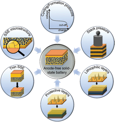 | ||
| Fig. 18 Promising design strategies for realizing high-performance and long-term stable anode-free solid-state batteries. (Reproduced with permission from ref. 42). | ||
Conflicts of interest
The authors declare no competing financial interest.References
- P. G. Bruce, S. A. Freunberger, L. J. Hardwick and J.-M. Tarascon, Nat. Mater., 2012, 11, 19–29 CrossRef CAS PubMed.
- Z. Yang, J. Zhang, M. C. Kintner-Meyer, X. Lu, D. Choi, J. P. Lemmon and J. Liu, Chem. Rev., 2011, 111, 3577–3613 CrossRef CAS PubMed.
- D. Larcher and J.-M. Tarascon, Nat. Chem., 2015, 7, 19–29 CrossRef CAS PubMed.
- J. W. Choi and D. Aurbach, Nat. Rev. Mater., 2016, 1, 1–16 Search PubMed.
- M. Li, J. Lu, X. Ji, Y. Li, Y. Shao, Z. Chen, C. Zhong and K. Amine, Nat. Rev. Mater., 2020, 5, 276–294 CrossRef CAS.
- M. Armand and J.-M. Tarascon, Nature, 2008, 451, 652–657 CrossRef CAS PubMed.
- J. B. Goodenough and K.-S. Park, J. Am. Chem. Soc., 2013, 135, 1167–1176 CrossRef CAS PubMed.
- Y.-K. Sun, Z. Chen, H.-J. Noh, D.-J. Lee, H.-G. Jung, Y. Ren, S. Wang, C. S. Yoon, S.-T. Myung and K. Amine, Nat. Mater., 2012, 11, 942–947 CrossRef CAS PubMed.
- C. Sun, J. Liu, Y. Gong, D. P. Wilkinson and J. Zhang, Nano Energy, 2017, 33, 363–386 CrossRef CAS.
- W. Zhang, J. Nie, F. Li, Z. L. Wang and C. Sun, Nano Energy, 2018, 45, 413–419 CrossRef CAS.
- Y. Lu, X. Rong, Y.-S. Hu, L. Chen and H. Li, Energy Storage Mater., 2019, 23, 144–153 CrossRef.
- P. Hartmann, C. L. Bender, M. Vračar, A. K. Dürr, A. Garsuch, J. Janek and P. Adelhelm, Nat. Mater., 2013, 12, 228–232 CrossRef CAS PubMed.
- N. Yabuuchi, K. Kubota, M. Dahbi and S. Komaba, Chem. Rev., 2014, 114, 11636–11682 CrossRef CAS PubMed.
- X. Xiang, K. Zhang and J. Chen, Adv. Mater., 2015, 27, 5343–5364 CrossRef CAS PubMed.
- W. Luo, F. Shen, C. Bommier, H. Zhu, X. Ji and L. Hu, Acc. Chem. Res., 2016, 49, 231–240 CrossRef CAS PubMed.
- H. Su, S. Jaffer and H. Yu, Energy Storage Mater., 2016, 5, 116–131 CrossRef.
- J.-Y. Hwang, S.-T. Myung and Y.-K. Sun, Chem. Soc. Rev., 2017, 46, 3529–3614 RSC.
- K. Abraham, ACS Energy Lett., 2020, 5, 3544–3547 CrossRef CAS.
- L. J. Hounjet, Energy Storage, 2022, 4, e309 CrossRef.
- M. D. Slater, D. Kim, E. Lee and C. S. Johnson, Adv. Funct. Mater., 2013, 23, 947–958 CrossRef CAS.
- Y. Huang, B. Cao, Z. Geng and H. Li, Acc. Mater. Res., 2024, 5(2), 184–193 CrossRef CAS.
- F. Wu, N. Chen, R. Chen, Q. Zhu, J. Qian and L. Li, Chem. Mater., 2016, 28, 848–856 CrossRef CAS.
- H. Che, S. Chen, Y. Xie, H. Wang, K. Amine, X.-Z. Liao and Z.-F. Ma, Energy Environ. Sci., 2017, 10, 1075–1101 RSC.
- J. J. Kim, K. Yoon, I. Park and K. Kang, Small Methods, 2017, 1, 1700219 CrossRef.
- H. Hou, Q. Xu, Y. Pang, L. Li, J. Wang, C. Zhang and C. Sun, Adv. Sci., 2017, 4, 1700072 CrossRef PubMed.
- C. Zhang, S. Gamble, D. Ainsworth, A. M. Slawin, Y. G. Andreev and P. G. Bruce, Nat. Mater., 2009, 8, 580–584 CrossRef CAS PubMed.
- A. Hayashi, K. Noi, A. Sakuda and M. Tatsumisago, Nat. Commun., 2012, 3, 1–5 Search PubMed.
- Q. Ma, M. Guin, S. Naqash, C.-L. Tsai, F. Tietz and O. Guillon, Chem. Mater., 2016, 28, 4821–4828 CrossRef CAS.
- Z. Zhang, Q. Zhang, J. Shi, Y. S. Chu, X. Yu, K. Xu, M. Ge, H. Yan, W. Li and L. Gu, Adv. Energy Mater., 2017, 7, 1601196 CrossRef.
- L. Duchêne, R.-S. Kühnel, E. Stilp, E. C. Reyes, A. Remhof, H. Hagemann and C. Battaglia, Energy Environ. Sci., 2017, 10, 2609–2615 RSC.
- Y. Noguchi, E. Kobayashi, L. S. Plashnitsa, S. Okada and J.-I. Yamaki, Electrochim. Acta, 2013, 101, 59–65 CrossRef CAS.
- T. Wei, Y. Gong, X. Zhao and K. Huang, Adv. Funct. Mater., 2014, 24, 5380–5384 CrossRef CAS.
- K. S. Ngai, S. Ramesh, K. Ramesh and J. C. Juan, Ionics, 2016, 22, 1259–1279 CrossRef CAS.
- D. Golodnitsky, E. Strauss, E. Peled and S. Greenbaum, J. Electrochem. Soc., 2015, 162, A2551 CrossRef CAS.
- J. W. Fergus, Solid State Ionics, 2012, 227, 102–112 CrossRef CAS.
- H. Tian, S. Liu, L. Deng, L. Wang and L. Dai, Energy Storage Mater., 2021, 39, 232–238 CrossRef.
- J. G. Kim, B. Son, S. Mukherjee, N. Schuppert, A. Bates, O. Kwon, M. J. Choi, H. Y. Chung and S. Park, J. Power Sources, 2015, 282, 299–322 CrossRef CAS.
- K. Kerman, A. Luntz, V. Viswanathan, Y.-M. Chiang and Z. Chen, J. Electrochem. Soc., 2017, 164, A1731 CrossRef CAS.
- J. Qian, B. D. Adams, J. Zheng, W. Xu, W. A. Henderson, J. Wang, M. E. Bowden, S. Xu, J. Hu and J. G. Zhang, Adv. Funct. Mater., 2016, 26, 7094–7102 CrossRef CAS.
- B. Thirumalraj, T. T. Hagos, C.-J. Huang, M. A. Teshager, J.-H. Cheng, W.-N. Su and B.-J. Hwang, J. Am. Chem. Soc., 2019, 141, 18612–18623 CrossRef CAS PubMed.
- Z. Tong, B. Bazri, S.-F. Hu and R.-S. Liu, J. Mater. Chem. A, 2021, 9, 7396–7406 RSC.
- C. Heubner, S. Maletti, H. Auer, J. Hüttl, K. Voigt, O. Lohrberg, K. Nikolowski, M. Partsch and A. Michaelis, Adv. Funct. Mater., 2021, 31, 2106608 CrossRef CAS.
- C. Li, Z.-Y. Wang, Z.-J. He, Y.-J. Li, J. Mao, K.-H. Dai, C. Yan and J.-C. Zheng, Sustainable Mater. Technol., 2021, 29, e00297 CrossRef CAS.
- X. Liu, X. Li, H. Li and H. B. Wu, Chem. – Eur. J., 2018, 24, 18293–18306 CrossRef CAS PubMed.
- J. Liang, J. Luo, Q. Sun, X. Yang, R. Li and X. Sun, Energy Storage Mater., 2019, 21, 308–334 CrossRef.
- J.-K. Kim, Y. J. Lim, H. Kim, G.-B. Cho and Y. Kim, Energy Environ. Sci., 2015, 8, 3589–3596 RSC.
- Y.-C. Jung, S.-M. Lee, J.-H. Choi, S. S. Jang and D.-W. Kim, J. Electrochem. Soc., 2015, 162, A704 CrossRef CAS.
- N. Boaretto, I. Garbayo, S. Valiyaveettil-SobhanRaj, A. Quintela, C. Li, M. Casas-Cabanas and F. Aguesse, J. Power Sources, 2021, 502, 229919 CrossRef CAS.
- K. Daems, P. Yadav, K. Dermenci, J. Van Mierlo and M. Berecibar, Renewable Sustainable Energy Rev., 2024, 191, 114136 CrossRef CAS.
- W. B. Nassir, T. H. Mengesha, J.-K. Chang, R. Jose and C.-C. Yang, Colloids Surf., A, 2024, 133839 CrossRef CAS.
- L. Herbers, W. Fettkether, S. Stuckenberg, D. Berghus, S. W. Martin, M. Winter and P. Bieker, Batteries Supercaps, 2024, e202300478 CrossRef CAS.
- K. Fu, Y. Gong, B. Liu, Y. Zhu, S. Xu, Y. Yao, W. Luo, C. Wang, S. D. Lacey and J. Dai, Sci. Adv., 2017, 3, e1601659 CrossRef PubMed.
- M. Sakuma, K. Suzuki, M. Hirayama and R. Kanno, Solid State Ionics, 2016, 285, 101–105 CrossRef CAS.
- Z. Bi and X. Guo, Energy Mater., 2022, 2, 200011 CrossRef CAS.
- X. Chen, W. He, L.-X. Ding, S. Wang and H. Wang, Energy Environ. Sci., 2019, 12, 938–944 RSC.
- K. J. Huang, G. Ceder and E. A. Olivetti, Joule, 2021, 5, 564–580 CrossRef CAS.
- Z. Karkar, M. S. Houache, C.-H. Yim and Y. Abu-Lebdeh, Batteries, 2024, 10, 24 CrossRef CAS.
- Y. Ma, L. Li, J. Qian, W. Qu, R. Luo, F. Wu and R. Chen, Energy Storage Mater., 2021, 39, 203–224 CrossRef.
- M. Egbuhuzor, S. Nwafor, C. Umunnakwe and S. Egoigwe, Thin Films-Deposition Methods and Applications, IntechOpen, 2023 Search PubMed.
- B. Wu, C. Chen, D. L. Danilov, R.-A. Eichel and P. H. Notten, Batteries, 2023, 9, 186 CrossRef CAS.
- D. Cheng, K. Tran, S. Rao, Z. Wang, R. van der Linde, S. Pirzada, H. Yang, A. Yan, A. Kamath and Y. S. Meng, ACS Energy Lett., 2023, 8, 4768–4774 CrossRef CAS.
- R. Vaidya, V. Selvan, P. Badami, K. Knoop and A. M. Kannan, Batteries Supercaps, 2018, 1, 75–82 CrossRef CAS.
- K. N. Jung, H. S. Shin, M. S. Park and J. W. Lee, ChemElectroChem, 2019, 6, 3842–3859 CrossRef CAS.
- K. Wiesener, D. Ohms, G. Benczúr-Ürmössy, M. Berthold and F. Haschka, J. Power Sources, 1999, 84, 248–258 CrossRef CAS.
- H. Karami, M. F. Mousavi and M. Shamsipur, J. Power Sources, 2003, 124, 303–308 CrossRef CAS.
- T. Liu, Y. Yuan, X. Tao, Z. Lin and J. Lu, Adv. Sci., 2020, 7, 2001207 CrossRef CAS PubMed.
- X. Lang, Y. Xiao, K. Cai, L. Li, Q. Zhang and R. Yang, Int. J. Energy Res., 2017, 41, 1504–1509 CrossRef CAS.
- Z. Li, Y. Lu, Q. Su, M. Wu, X. Que and H. Liu, ACS Appl. Mater. Interfaces, 2022, 14, 5402–5413 CrossRef CAS PubMed.
- G. Homann, P. Meister, L. Stolz, J. P. Brinkmann, J. R. Kulisch, T. Adermann, M. Winter and J. Kasnatscheew, ACS Appl. Energy Mater., 2020, 3, 3162–3168 CrossRef CAS.
- Z. Zhang, Y. Zhao, S. Chen, D. Xie, X. Yao, P. Cui and X. Xu, J. Mater. Chem. A, 2017, 5, 16984–16993 RSC.
- H. S. Shin, W. G. Ryu, M. S. Park, K. N. Jung, H. Kim and J. W. Lee, ChemSusChem, 2018, 11, 3184–3190 CrossRef CAS PubMed.
- H. W. Kim, P. Manikandan, Y. J. Lim, J. H. Kim, S.-C. Nam and Y. Kim, J. Mater. Chem. A, 2016, 4, 17025–17032 RSC.
- S. H. Kim, J. H. Kim, S. J. Cho and S. Y. Lee, Adv. Energy Mater., 2019, 9, 1901841 CrossRef CAS.
- S.-H. Kim, K.-H. Choi, S.-J. Cho, J. Yoo, S.-S. Lee and S.-Y. Lee, Energy Environ. Sci., 2018, 11, 321–330 RSC.
- Y. Gambe, Y. Sun and I. Honma, Sci. Rep., 2015, 5, 8869 CrossRef CAS PubMed.
- A. Shao, X. Tang, M. Zhang, M. Bai and Y. Ma, Adv. Energy Sustainability Res., 2022, 3, 2100197 CrossRef CAS.
- P. Zhao, J. Pan, D. Zhang, Y. Tang, Z. Tai, Y. Liu, H. Gao and F. Huang, Batteries, 2023, 9, 381 CrossRef CAS.
- B. Qiao, S. Mohapatra, J. Lopez, G. M. Leverick, R. Tatara, Y. Shibuya, Y. Jiang, A. France-Lanord, J. C. Grossman and R. Gómez-Bombarelli, ACS Cent. Sci., 2020, 6, 1115–1128 CrossRef CAS PubMed.
- S. J. An, J. Li, C. Daniel, D. Mohanty, S. Nagpure and D. L. Wood III, Carbon, 2016, 105, 52–76 CrossRef CAS.
- P. Li, H. Kim, J. Ming, H.-G. Jung, I. Belharouak and Y.-K. Sun, EScience, 2021, 1, 3–12 CrossRef.
- P. P. Paul, E. J. McShane, A. M. Colclasure, N. Balsara, D. E. Brown, C. Cao, B. R. Chen, P. R. Chinnam, Y. Cui and E. J. Dufek, Adv. Energy Mater., 2021, 11, 2100372 CrossRef CAS.
- C.-L. Tsai, V. Roddatis, C. V. Chandran, Q. Ma, S. Uhlenbruck, M. Bram, P. Heitjans and O. Guillon, ACS Appl. Mater. Interfaces, 2016, 8, 10617–10626 CrossRef CAS PubMed.
- Y.-G. Lee, S. Fujiki, C. Jung, N. Suzuki, N. Yashiro, R. Omoda, D.-S. Ko, T. Shiratsuchi, T. Sugimoto and S. Ryu, Nat. Energy, 2020, 5, 299–308 CrossRef CAS.
- Y. Yang, W. Yuan, X. Zhang, Y. Ke, Z. Qiu, J. Luo, Y. Tang, C. Wang, Y. Yuan and Y. Huang, Appl. Energy, 2020, 276, 115464 CrossRef CAS.
- T. A. Zegeye, W.-N. Su, F. W. Fenta, T. S. Zeleke, S.-K. Jiang and B. J. Hwang, ACS Appl. Energy Mater., 2020, 3, 11713–11723 CrossRef CAS.
- Z. Tu, M. J. Zachman, S. Choudhury, K. A. Khan, Q. Zhao, L. F. Kourkoutis and L. A. Archer, Chem. Mater., 2018, 30, 5655–5662 CrossRef CAS.
- W. Chen, R. V. Salvatierra, M. Ren, J. Chen, M. G. Stanford and J. M. Tour, Adv. Mater., 2020, 32, 2002850 CrossRef CAS PubMed.
- Z. T. Wondimkun, T. T. Beyene, M. A. Weret, N. A. Sahalie, C.-J. Huang, B. Thirumalraj, B. A. Jote, D. Wang, W.-N. Su and C.-H. Wang, J. Power Sources, 2020, 450, 227589 CrossRef CAS.
- A. A. Assegie, J.-H. Cheng, L.-M. Kuo, W.-N. Su and B.-J. Hwang, Nanoscale, 2018, 10, 6125–6138 RSC.
- L. H. Abrha, T. A. Zegeye, T. T. Hagos, H. Sutiono, T. M. Hagos, G. B. Berhe, C.-J. Huang, S.-K. Jiang, W.-N. Su and Y.-W. Yang, Electrochim. Acta, 2019, 325, 134825 CrossRef CAS.
- Z. T. Wondimkun, W. A. Tegegne, J. Shi-Kai, C.-J. Huang, N. A. Sahalie, M. A. Weret, J.-Y. Hsu, P.-L. Hsieh, Y.-S. Huang and S.-H. Wu, Energy Storage Mater., 2021, 35, 334–344 CrossRef.
- N. A. Sahalie, Z. T. Wondimkun, W.-N. Su, M. A. Weret, F. W. Fenta, G. B. Berhe, C.-J. Huang, Y.-C. Hsu and B. J. Hwang, ACS Appl. Energy Mater., 2020, 3, 7666–7679 CrossRef CAS.
- C. Li, X. Zhang, W. He, G. Xu and R. Sun, J. Power Sources, 2020, 449, 227596 CrossRef CAS.
- Z. Wei, S. Chen, J. Wang, Z. Wang, Z. Zhang, X. Yao, Y. Deng and X. Xu, J. Mater. Chem. A, 2018, 6, 13438–13447 RSC.
- Z. Wei, S. Chen, J. Wang, Z. Wang, Z. Zhang, X. Yao, Y. Deng and X. Xu, J. Power Sources, 2018, 394, 57–66 CrossRef CAS.
- Y. J. Nam, S.-J. Cho, D. Y. Oh, J.-M. Lim, S. Y. Kim, J. H. Song, Y.-G. Lee, S.-Y. Lee and Y. S. Jung, Nano Lett., 2015, 15, 3317–3323 CrossRef CAS PubMed.
- J. Lee, J. Song, H. Lee, H. Noh, Y.-J. Kim, S. H. Kwon, S. G. Lee and H.-T. Kim, ACS Energy Lett., 2017, 2, 1232–1239 CrossRef CAS.
- T. Sato, T. Morinaga, S. Marukane, T. Narutomi, T. Igarashi, Y. Kawano, K. Ohno, T. Fukuda and Y. Tsujii, Adv. Mater., 2011, 23, 4868 CrossRef CAS PubMed.
- T. Matsuo, Y. Gambe, Y. Sun and I. Honma, Sci. Rep., 2014, 4, 6084 CrossRef CAS PubMed.
- N. Takami, K. Yoshima and Y. Harada, J. Electrochem. Soc., 2016, 164, A6254 CrossRef.
| This journal is © The Royal Society of Chemistry 2024 |


