 Open Access Article
Rotating ellipsoidal catalytic micro-swimmers via glancing angle evaporation†
Alice
Kirvin
 a,
David
Gregory
 a,
Andrew
Parnell
 b,
Andrew I.
Campbell
a and
Stephen
Ebbens
*a
aDepartment of Chemical and Biological Engineering, University of Sheffield, Sheffield S1 4NL, UK. E-mail: s.ebbens@sheffield.ac.uk
bDepartment of Physics and Astronomy, University of Sheffield, Sheffield S3 7RH, UK
First published on 21st September 2021
Abstract
The ability to generate rotation in ellipsoidal catalytic micro swimming devices by catalyst deposition at glancing angles allows reliable access to circling trajectories. This behaviour could enable propulsive ellipsoids to gather cargo and enhance mixing at small scales. Catalytically propelled colloidal rotation has been previously achieved in spherical swimming devices by means of neighbour shadowing during catalyst deposition leading to non-symmetrical coatings. However in this work shadowing effects arise due to the ellipsoid's inherent anisotropy, removing the requirement for a closely packed colloidal crystal monolayer. We use geometric analysis of the catalyst deposition process, and mechanistic understanding to propose a link between the observed trajectories and the catalyst distribution and suggest further routes to improve control of rotation rates.
Introduction
Motile micron scale colloids driven by the catalytic decomposition of fuel dissolved in fluids have received much recent attention, motivated by potential applications as autonomous microfluidic transporter systems1 including medical diagnostics,2 drug delivery3 and environmental remediation.4 One well studied system is catalytic Janus colloids: spherical particles coated with a catalyst on one half. A significant amount of research into propulsive Janus colloids has focused on motion driven by the decomposition of hydrogen peroxide by platinum metal.5 These catalytic Janus colloids produce directed motion via bubble release or self-phoresis phenomena depending on their size, and catalyst activity.6 Prior areas of research focus for this system include developing methods to direct individual or groups of motile colloids,7 strategies for cargo transport,8 and fundamental investigations into propulsion mechanisms.9 Recently, theory and simulations have also paid particular attention to the collective behaviour that can emerge due to interactions between these active colloids mediated by chemical fields and hydrodynamics.10 For much of this previous work there has been a strong focus on spherical particles, due to their accessibility compared to other geometries. However, depositing a similar Janus catalytic structure on ellipsoids may also produce a propulsive effect, and the shape asymmetry could introduce new phenomena. Theoretical studies have considered some of the possible behaviours for ellipsoidal catalytic Janus colloid systems. For example, the way in which geometry and aspect ratio are expected to alter propulsion velocity was investigated by Ibrahim et al., for the case of diffusiophoretic propulsion.11 In addition, predictions have been made that motile ellipsoidal particles will be guided by chemically patterned substrates in a more complex manner compared to spheres.12 Ellipsoids may also be expected to display enhanced opportunities for cargo capture by exploiting their shape asymmetry and larger surface area compared to spherical colloids of the same volume; and allow access to new collective behaviour.Catalytically driven translational and rotational propulsive behaviour for Janus ellipsoids has previously been documented, however a range of uncontrolled trajectories were observed.13 In this work we investigate the potential to exert further control over the trajectories of similar catalytic Janus ellipsoids, Fig. 1, via platinum catalytic coatings capable of decomposing hydrogen peroxide applied at glancing angles. We have previously shown that glancing angle catalyst deposition applied to close-packed spherical colloids, produced catalytic Janus colloids with high angular propulsion velocities, i.e. spinners.14 Geometrically distinct spinners have also been produced by other means in the literature; light activation of semiconductor swimmers has been shown to produce translational or rotational motion depending on the wavelength of light used, and the swimmers initial orientation.15 Whilst solid platinum plates that have been cut to resemble twisted stars also produce somewhat significant rotational speeds when exposed to hydrogen peroxide fuel.16 Producing spinning particles can have a range of applications, including realising small scale mixing devices, or applying stringency forces during anti-body based cargo capture to enhance selectivity.17 For spheres, shadowing by near-neighbours within a crystalline monolayer during glancing angle catalyst deposition produced complex coating shapes, deviating from the hemispherical coating obtained by normal evaporation. Breaking the coatings’ symmetry in this way was thought to have been responsible for the observed enhanced rotations, based on mechanistic evidence that slip-velocity is determined by the distribution of catalytic activity, which links to thickness and distribution.18 While the catalytic spheres’ rotation rates were significant, the strict requirement to form an initial close packed monolayer, in order to access this behaviour, is restrictive. However, when moving to ellipsoids, geometric considerations mean that isolated ellipsoids can exhibit variations in catalytic coating thickness and perimeter shape, due to “self” shadowing. In addition, there may be further advantages for causing ellipsoids to rotate, compared to spheres, such as greater potential to enhance mixing and cargo capture benefits. To assess this potential, here we compare the trajectories of ellipsoids functionalised via normal, and glancing angle deposition, and analyse these to statistically assess the effect of glancing angles on rotational behaviour. We also apply ray-tracing to geometrically determine the glancing angle catalyst distributions and relate these to our observations.
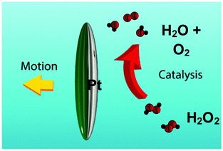 | ||
| Fig. 1 Schematic of an ellipsoidal micro swimmer, coated along its major axis with platinum (shaded grey) decomposing hydrogen peroxide fuel. | ||
Experimental
Pt coated ellipsoid preparation
Ellipsoidal colloids were produced by stretching spherical polystyrene colloids with an original diameter of 2.16 μm (Sigma- Aldrich), using the method devised by Keller et al.19 The spherical colloids were thoroughly mixed in a 25% by weight polyvinyl alcohol (PVA) (Mowiol 4-88 Sigma- Aldrich) water solution, this mixture was spread thinly in a Petri dish and allowed to dry for 3 days. The resulting film (thickness 0.329 ± 0.0129 mm) contained an even distribution of embedded isolated spherical colloids. This film was mounted in a custom-built stretching equipment that could apply a well-defined uni-axial displacement to the film. This apparatus was dipped into an oil bath at 135 °C. The temperature was chosen to be above the glass transition temperature, Tg, of the polystyrene colloids (105 °C) and the PVA film matrix (∼38 °C). The process involved immersion in the oil bath followed by a rapid stretch and removal which provides a rapid quench below Tg. The film was stretched to 4.5 times its original length and after cooling the apparatus, the film was released from the clamp. To remove the stretched colloids from the PVA matrix, 10 mg pieces of matrix were dissolved in a 70![[thin space (1/6-em)]](https://www.rsc.org/images/entities/char_2009.gif) :
:![[thin space (1/6-em)]](https://www.rsc.org/images/entities/char_2009.gif) 30 solution of iso-propyl alcohol (99.9%, Sigma-Aldrich) and deionised water, and heated to 75 °C to dissolve the PVA, resulting in ellipsoidal colloids in a hot PVA solution. Whilst still hot, (to avoid PVA solidifying), the resulting suspension was centrifuged at 14
30 solution of iso-propyl alcohol (99.9%, Sigma-Aldrich) and deionised water, and heated to 75 °C to dissolve the PVA, resulting in ellipsoidal colloids in a hot PVA solution. Whilst still hot, (to avoid PVA solidifying), the resulting suspension was centrifuged at 14![[thin space (1/6-em)]](https://www.rsc.org/images/entities/char_2009.gif) 000 rpm for 20 minutes and the supernatant replaced with deionised water. This cleaning process was repeated three times. The cleaned colloids were deposited onto pre-cleaned glass slides by pipetting the suspension into hydrogel wells to concentrate the colloids in certain locations of the slide.
000 rpm for 20 minutes and the supernatant replaced with deionised water. This cleaning process was repeated three times. The cleaned colloids were deposited onto pre-cleaned glass slides by pipetting the suspension into hydrogel wells to concentrate the colloids in certain locations of the slide.
The ellipsoidal colloids were then coated first with 10 nm of chromium and then with 20 nm of platinum (Kurt J Lesker 99.99% purity) while localised on the slide. Platinum was deposited via electron beam evaporation (Moorfield minilab) at ≈1 × 10⁻⁷ atm. Coatings were applied at two angles, normal evaporation (θ = 90°, see Fig. 2) and for a separate batch of equivalent colloids at a glancing angle (θ = 60°) using custom angle changing equipment.
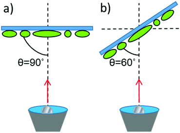 | ||
| Fig. 2 Schematic for metal evaporation (a) Normal evaporation (b) Glancing angle evaporation. Note that the ellipsoids major axis alignment on the substrate is uncontrolled (see Fig. 3). | ||
SEM observation
Colloids were prepared for imaging by pipetting a suspension in water onto a cleaned glass slide. The colloids were allowed to dry thoroughly before the slide was cut down to 1.5 cm × 1.5 cm and coated with gold for 20 seconds resulting in ∼10 nm of gold, using a sputter coater (AGAR Sputter Coater model 108). The colloids were imaged in a Jeol JSM-6010LA Analytical SEM (SEI, 15 KeV).Optical observation of colloidal motion
Ellipsoidal colloids were transferred to solution by rubbing wetted lens tissue onto the Pt coated, colloid covered glass slides. The lens tissue was then shaken in a small volume of deionised water which was separated from the tissue to produce a low concentration volume of the desired colloids in deionised water. In order to assess the fuelled catalytic motion of the Janus ellipsoids, hydrogen peroxide was added to these suspensions to produce 10% wt aqueous solutions. The suspension was observed at the bottom surface of a quartz glass cuvette using an inverted microscope (Nikon eclipse T-100 microscope) equipped with a Pixelink PL-B742F camera. Videos of the colloids suspended in solution were recorded to capture their diffusive/propulsive motion at a framerate of 33 fps and a resolution of 640 × 480 pixels. Control experiments without the addition of hydrogen peroxide were also performed in the same manner. The x, y coordinates of ellipsoid and tracer particles were determined as a function of time using custom image analysis algorithms written using LabVIEW. The orientation of the anisotropic ellipsoids (θorientation) was determined as a function of time using a pattern recognition algorithm to determine the major axis angle.As described elsewhere in detail,20 assuming that the propulsion direction is fixed in relation to the orientation of the body of the propulsive colloid, the magnitude of the Brownian translational diffusion, D, rotation time (τR = 1/Dr, where Dr is the Brownian rotational diffusion constant) and angular (ω) and translational velocity (v) can be determined by fitting the mean-square displacement (MSD) data as a function of time (ΔL2 〈t〉) to the following expression from Ebbens et al.:21
 | (1) |
This analysis was applied to the raw x,y, coordinates for the elliptical colloids via fitting with suitable physical constraints (all returned values >0, and physically sensible constraints applied to D and Dr) using OriginPro.
Ray tracing
Geometrical prediction of the distribution of evaporated metal coating on the ellipsoidal colloid surface was carried out using ray-tracing analysis performed with Matlab, as described in detail previously,14 however in this case the array of spheres were replaced with an isolated ellipsoid with an aspect ratio of 3.55, chosen to match the average measured dimensions of our experimentally produced colloids.Results
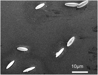
Fig. 3 shows a representative SEM image of the stretched PS colloids. Qualitatively it is apparent that reasonably uniform ellipsoids have been successfully produced. Quantitative analysis of 26 ellipsoidal colloids reveals that the mean major axis is 8.05 ± 0.98 μm and the mean minor axis is 2.33 ± 0.34 μm, giving a mean aspect ratio of 3.55 ± 0.78.Ellipsoidal motion near an interface and in bulk solution
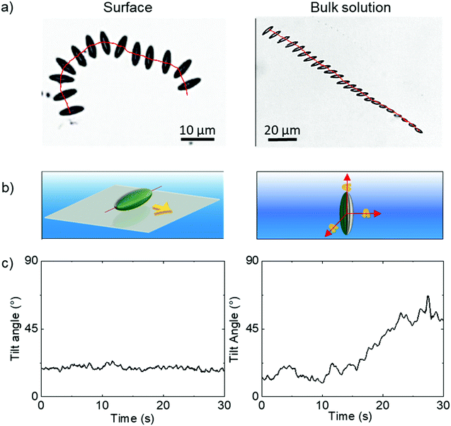
Having confirmed the particles’ geometry, the ellipsoids were coated with Pt while localised on a planar substrate, exploiting the previously demonstrated directionality of metal evaporation to produce a half-coated structure, in this case producing a Janus ellipsoid structure aligned relative to the long axis as shown in Fig. 1. The ellipsoidal particles were suspended in an aqueous hydrogen peroxide solution (10 wt%), where the Pt catalyses the decomposition of the fuel.Ellipsoids in hydrogen peroxide fuel were predominantly found to sediment to the lower boundary of the cuvette. Around 30 ellipsoids were found to have sedimented to the lower boundary, however only 10 ellipsoids were found still swimming in the bulk solution. In all cases where sedimentation occurs, the proximity of the ellipsoids to the boundary resulted in them lying relatively flat against the cuvette wall. Analysis revealed that fuelled sedimented ellipsoids moved along this horizontal 2D plane propulsively, as shown in the example time lapse image with superimposed trajectory, (Fig. 4a LHS), and schematically in Fig. 4b. Fluctuations in the apparent long axis length in the 2D microscope images were determined via image analysis, and used to estimate the tilt angle of the ellipsoid with respect to horizontal, Fig. 4c. For sedimented ellipsoids the tilt angle remains more or less constant. A small number of ellipsoids were also observed undergoing propulsion in bulk solution, far from the cuvette walls. Ellipsoids propelling in the bulk fluid have more degrees of freedom, they can rotate freely around each of their axes (Fig. 4b RHS) and also rapidly move in and out of the microscopes focal plane due to sedimentation/propulsion. Fig. 4a illustrates this effect, in a time-lapse image with overlaid trajectory, showing the ellipsoid is undergoing complex rotations. For this short, well focused trajectory section the deviations from horizontal alignment were quantified, Fig. 4c.
In order to maintain as much experimental control of the ellipsoidal micro swimmers as possible we conducted further quantitative trajectory analysis near the cuvettes lower surface and focused on the dynamics of the ellipsoidal micro swimmers under this constraint. However, the observation that some ellipsoids remain in the bulk solution suggests a balance of gravitaxis effects22 with sedimentation can occur, and opens the chance for future study in bulk solutions where highly complex trajectories may be expected.
All ellipsoids moving near the planar substrate were qualitatively observed to instantaneously translate perpendicular to the orientation of their major axis, (Fig. 4a and b). Similar to the previous report,13 some ellipsoids coated in the normal evaporation direction (θ = 90°) showed almost linear paths, while others showed appreciable driven rotations resulting in circling behaviour, Fig. 5b and c. The corresponding MSD versus time plots show the expected parabolic behaviour for linear propulsive trajectories (Fig. 5e) and oscillating features for circling trajectories, Fig. 5f. MSD fitting to Equation 1 revealed that the mean translational velocity for all ellipsoids in this batch was 4.87 ± 0.59 μms−1 and a range of angular velocities between 1 × 10⁻⁷ and 0.484 rads−1. The origin of the non-zero angular velocity has previously been assigned to unavoidable heterogeneity in coating shape and deviation in colloid geometry from the ideal, which break the symmetry in the idealised Janus structure,5 as discussed further below. In contrast, in the absence of fuel, ellipsoids displayed only small displacements and random rotations, see Fig. 5a, which were quantitatively confirmed to be consistent with hindered Brownian motion alone via linear MSD versus time plots, Fig. 5d. This control experiment confirms that the observed motion is due to the catalytic reaction. Quantitative determination of the fluctuation with time of the angle between the instantaneous direction of motion and the colloids major axis orientation (Fig. 6a), is shown in Fig. 6b for one typical ellipsoid, and is seen to remain close to 90°. Averaged over all normally evaporated ellipsoidal colloid trajectories (n = 12) the orientation versus direction of travel offset angle is 89.1° ± 16.1. This average is very close to the expected perpendicular motion. The standard deviation for this measurement is relatively high when the entire population of swimmers is considered, however when only ballistic, or close to ballistically translating colloids are measured, an average angle of 90.2° ± 8.6 is obtained. This suggests that higher rotational velocity leads to higher spread in this value.
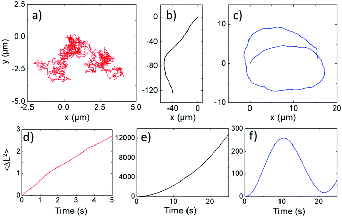 | ||
| Fig. 5 Normally evaporated ellipsoidal trajectories (a) In water (b and c) In 10% hydrogen peroxide (d–f) corresponding mean square displacements versus time for trajectories (a–c). | ||
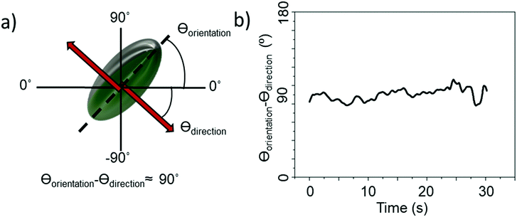 | ||
| Fig. 6 (a) Diagram showing axis assignment and angles of interest (b) difference between orientation of ellipsoid body long axis and direction of travel over the course of a 30 s video. | ||
Taken together, these observations strongly suggest: (i) the propulsive motion direction is perpendicular to the orientation of the catalyst cap, and (ii) the platinum coated half adopts a constant perpendicular alignment relative to the boundary as shown in Fig. 4b, LHS, with Brownian rotation about the grey axis quenched. This latter point follows from the first: if rotation about the major axis was unrestricted, the ellipsoids could not make translations in a persistent direction, as Brownian rotation about this small diameter axis would be very rapid. The origin of this boundary alignment effect has been thoroughly investigated for Janus spheres,23 and attributed to specific mechanistic details, therefore it seems likely that a similar phoretic mechanism drives the motion of these analogous Janus ellipsoids: certainly, no indication of bubble propulsion was observed in our experiments. Note that our current observations could not directly discern if ellipsoids are translating away from or towards the Pt cap. We arbitrarily depict motion occurring away from the Pt cap in line with previous observations for spherical Janus swimmers under similar conditions and made from equivalent materials.24
Glancing angle deposition
Similar observations were performed for a second batch of ellipsoidal particles coated at a glancing angle (θ = 60°). The motion and general features of behaviour for the glancing angle ellipsoids are equivalent to those described above, however the trajectories now all show persistent circling when observed in 2D confinement, reflecting the desired controlled introduction of angular velocity due to changes in catalyst distribution associated with glancing angle deposition, Fig. 7a. Corresponding MSD data shows the distinctive oscillations consistent with rotational motion, which can be fitted by eqn (1), describing propulsive colloids undergoing driven translational and rotational propulsive motion, Fig. 7b.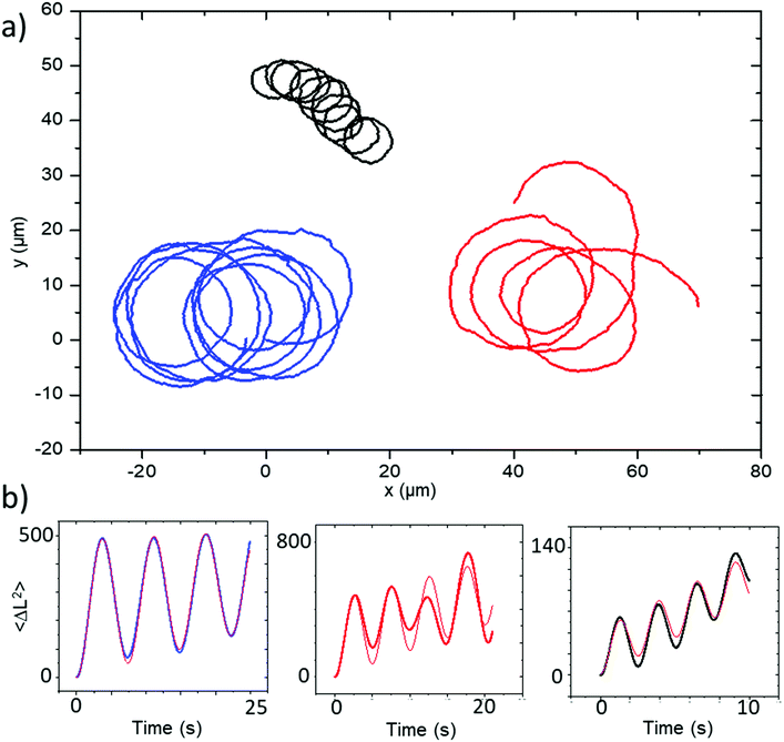 | ||
| Fig. 7 (a) Trajectories and (b) corresponding MSD plots representative of the batch of Janus ellipsoids coated at a glancing angle of 60°. MSD fitting plots are shown in red. | ||
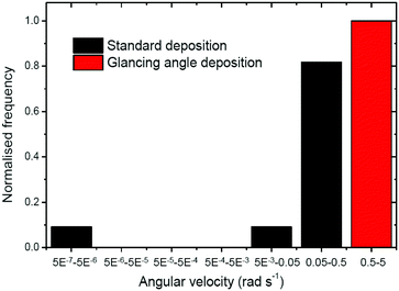
This fitting procedure allows quantification of the angular velocity for each glancing angle ellipsoid, revealing a mean angular velocity of 1.88 ± 0.94 rad s−1 (n = 12). This is an increase of around sixteen times compared with the average angular velocity for the normally evaporated batch (0.11 ± 0.088 rad s−1). The range of angular velocities observed in the glancing angle batch varies from 0.72 rad s−1 to 3.00 rad s−1. The lower limit of this range is still double that of the fastest spinning Janus ellipsoid coated normally. Fig. 8 compares the distribution of angular velocities, clearly showing that increased spining is associated with glancing angles depositon, and a clear separation between the glancing and normal deposition batches. The mean translational velocity of spinning swimmers was 7.49 ± 3.68 μms−1, a slight increase on the mean translational velocity for conventionally coated ellipsoidal swimmers.
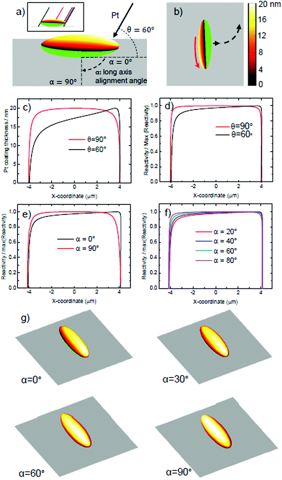
To understand the origin of the introduced spin, it is necessary to consider the effect of evaporation at glancing angles on the depositied catalyst coating shape. Using geometrical analysis and ray-tracing it is possible to accurately determine the boundary of the catalytically coated region, and estimate the catalyst coating thickness at each point on the coated region. For isolated ellipsoids that are not shadowed by neighours, there are two variables that determine the predicted coating distribution: the glancing angle, θ, as defined in Fig. 2, and the orientation of the long axis of the ellipsoid, relative to the incident Pt direction, α, as shown in Fig. 9a. Fig. 9a shows the predicted Pt coating distribution for the glancing angle considered here (θ = 60°) at α = 0°. It is clear that the ellipsoids’ body shadows evaporation, resulting in a shift in the coatings perimeter, so that coating occurs below the “nose” of the ellipsoid at one end, but cannot reach the nose at the other. In addition, a greater thickness of coating occurs at one end of the ellipsoid, while the other end shows a thinned coating. This is apparent when considering the points at which the thickness reduces to less than 9 nm, and the calculated maximum thickness. Fig. 9b shows this coated ellipsoid orientated relative to a planar surface, as it is during propulsive motion. Based on the established link between catalyst thickness, actvity, and slip-velocity for electrokinetic colloids,18 the additional coating thickness at one end of the colloid would be expected to cause a higher slip velocity, which would generate a rotation of the ellipsoid. In Fig. 9c we compare the calculated platinum coating thickness distribution along the long axis of the ellipsoidal colloid, to illustrate this point further. It is clear that while normal evaporation (θ = 90°) produces a symmetrical profile, at the experimental glancing angle (θ = 60°), a considerable asymmetry is present. By using the previous quantitative relationship in ref. 16, we can convert the thickness variations into relative surface reactivity variations, Fig. 9d. While the asymmetry is less striking, it still clearly remains. When considered together with the overall Janus structure, which imparts an additional translational thrust perpendicular to the long axis, these additional reactivity variations from one end of the ellipsoid will produce a corresponding modulation to slip velocity, explaining the circling behaviours observed. In reality our coating structure will vary from ellipsoid to ellipsoid, as we have not controlled the long axis alignment, α in our experiment. To do so would require a method to align the ellipsoidal long axis of all colloids on the evaporation substarte. In fact, based on the apparent random orientation of ellipsoids on the substrate before evaporation (Fig. 3) it is reasonable to assume a uniform distribution of α. In Fig. 9e we compare the reacitivity asymmetry along the long axis for two extreme cases, α = 0°, discussed above, and α = 90°. It is clear that α = 90° removes the asymmetry, and so we would expect this to be a special case with no rotation regardless of glancing angle. An ellipsoid that happened to be in this alignment would hence not be expected to produce additional rotations. Fig. 9f displays the more likely scenarios, at intermediate angles of α. In these intermediate cases, reactivity asymmetry reduces as α increases towards 90°. Fig. 9g aids direct visualisation of the origin of this reduction in asymmetry: it can be seen that the misalignment of the long axis with the evaporation direction progressively reduces the end to end variations in thickness, as the coating rotates about the long axis. This is equivalent to the effect of increasing the glancing angle θ back towards 90° (see ESI†). The fact that α introduces variance in reaction asymmetry, appears to agree well with our findings, in that we observe a range of circling trajectories with different angular velocities, but which are consistently enhanced compared to the defect induced rotations present during normal evaporation. It is clear that gaining control over the alignment angle would allow batches of ellipsoids matching specific predicted coating geometries to be studied, rather than mixtures. This could further clarify the link between the distribution of Pt catalyst and rotational behaviour.
Conclusions
The experimental investigation of ellipsoidal catalytic Janus colloids capable of producing motion via decomposing hydrogen peroxide has revealed that catalyst deposition at glancing angles allows reliable access to circular trajectories. Geometric analysis of the coating procedure suggests how the shadowing effects introduced at glancing angles are related to the observed additional rotational propulsion. Shadowing produces variations in catalyst thickness, and existing propulsion mechanism understanding relates these to variations in slip-velocity that are consistent with driven rotations. These results may be of direct use for envisaged applications: increased surface area compared to spheres of the same volume, combined with rotation may enhance the ability to capture cargo at the ellipsoids surface, compared to spheres. Additionally, the rotary motion could be exploited to enhance mixing in low Reynolds number environments, much more effectively than spheres. In contrast to previous work demonstrating the ability to make catalytic Janus spheres rotate, altering the ellipsoidal catalyst symmetry does not rely on shadowing from neighbours within a close packed crystal, increasing the accessibility of this effect. The potential to extend these findings to produce further control of ellipsoidal motion appears strong. It may be possible to exploit electric fields25 or substrate patterning to align the ellipsoidal long axes on a planar substrate. This would allow orientational control of the ellipsoids during glancing angle catalyst deposition, reducing the spread of angular velocities, and enabling consistent access to maximum rotation rates. Alignment could also enable the ability to tune angular velocity precisely. Our study mainly concerns ellipsoidal colloids moving near a 2D interface; however, we did observe some colloids in the bulk fluid. Combining improved rotational control, with the ability to track ellipsoids motion in 3D also appears to be a promising extension, as the interplay of the 2D rotational phenomena reported here with gravitaxis could lead to access to complex spiralling trajectories, in similar fashion to those observed for spheres.26Conflicts of interest
There are no conflicts to declare.References
- S. J. Ebbens, Active colloids: progress and challenges towards realising autonomous applications, Curr. Opin. Colloid Interface Sci., 2016, 21, 14–23 CrossRef CAS.
- M. García, et al., Micromotor-based lab-on-chip immunoassays, Nanoscale, 2013, 5, 1325–1331 RSC.
- W. Gao, B. E. F. de Ávila, L. Zhang and J. Wang, Targeting and isolation of cancer cells using micro/nanomotors, Adv. Drug Delivery Rev., 2018, 125, 94–101 CrossRef CAS PubMed.
- J. Parmar, D. Vilela, K. Villa, J. Wang and S. Sánchez, Micro- and Nanomotors as Active Environmental Microcleaners and Sensors, J. Am. Chem. Soc., 2018, 140, 9317–9331 CrossRef CAS.
- J. Howse, et al., Self-Motile Colloidal Particles: from Directed Propulsion to Random Walk, Phys. Rev. Lett., 2007, 99, 48102 CrossRef.
- S. Wang and N. Wu, Selecting the Swimming Mechanisms of Colloidal Particles: bubble Propulsion versus Self-Diffusiophoresis, Langmuir, 2014, 30, 3477–3486 CrossRef CAS PubMed.
- S. J. Ebbens and D. A. Gregory, Catalytic Janus Colloids: controlling Trajectories of Chemical Microswimmers, Acc. Chem. Res., 2018, 51, 1931–1939 CrossRef CAS PubMed.
- J. Wang, Cargo-towing synthetic nanomachines: towards active transport in microchip devices, Lab Chip, 2012, 12, 1944–1950 RSC.
- Y. Ibrahim, R. Golestanian and T. B. Liverpool, Multiple phoretic mechanisms in the self-propulsion of a Pt-insulator Janus swimmer, J. Fluid Mech., 2017, 828, 318–352 CrossRef CAS.
- P. Illien, R. Golestanian and A. Sen, ‘Fuelled’ motion: phoretic motility and collective behaviour of active colloids, Chem. Soc. Rev., 2017, 46, 5508–5518 RSC.
- Y. Ibrahim, R. Golestanian and T. B. Liverpool, Shape dependent phoretic propulsion of slender active particles, Phys. Rev. Fluids, 2018, 3, 33101 CrossRef.
- W. E. Uspal, M. N. Popescu, M. Tasinkevych and S. Dietrich, Shape-dependent guidance of active Janus particles by chemically patterned surfaces, New J. Phys., 2018, 20, 1–19 CrossRef.
- O. Shemi and M. J. Solomon, Self-Propulsion and Active Motion of Janus Ellipsoids, J. Phys. Chem. B, 2018, 122, 10247–10255 CrossRef CAS PubMed.
- R. J. Archer, A. I. Campbell and S. J. Ebbens, Glancing angle metal evaporation synthesis of catalytic swimming Janus colloids with well defined angular velocity, Soft Matter, 2015, 11, 6872–6880 RSC.
- É. O’Néel-Judy, D. Nicholls, J. Castañeda and J. G. Gibbs, Light-Activated, Multi-Semiconductor Hybrid Microswimmers, Small, 2018, 14, 1801860 CrossRef.
- A. M. Brooks, et al., Shape-directed rotation of homogeneous micromotors via catalytic self-electrophoresis, Nat. Commun., 2019, 10, 495 CrossRef CAS PubMed.
- A. van Reenen, A. M. de Jong and M. W. J. Prins, Accelerated Particle-Based Target Capture—The Roles of Volume Transport and Near-Surface Alignment, J. Phys. Chem. B, 2013, 117, 1210–1218 CrossRef CAS PubMed.
- A. Campbell, S. Ebbens, P. Illien and R. Golestanian, Experimental Observation of Flow Fields Around Active Janus Spheres, Nat. Commun., 2019, 10, 3952 CrossRef PubMed.
- C. C. Ho, A. Keller, J. A. Odell and R. H. Ottewill, Preparation of monodisperse ellipsoidal polystyrene particles, Colloid Polym. Sci., 1993, 271, 469–479 CrossRef CAS.
- S. Ebbens, R. A. L. Jones, A. J. Ryan, R. Golestanian and J. R. Howse, Self-assembled autonomous runners and tumblers, Phys. Rev. E: Stat., Nonlinear, Soft Matter Phys., 2010, 82, 015304(R) CrossRef PubMed.
- S. Ebbens, R. A. L. Jones, A. J. Ryan, R. Golestanian and J. R. Howse, Self-assembled autonomous runners and tumblers, Phys. Rev. E: Stat., Nonlinear, Soft Matter Phys., 2010, 82, 15304 CrossRef PubMed.
- A. I. Campbell and S. J. Ebbens, Gravitaxis in Spherical Janus Swimming Devices, Langmuir, 2013, 29, 14066–14073 CrossRef CAS.
- S. Das, et al., Boundaries can steer active Janus spheres, Nat. Commun., 2015, 6(1), 8999 CrossRef CAS.
- S. J. Ebbens and J. R. Howse, Direct Observation of the Direction of Motion for Spherical Catalytic Swimmers, Langmuir, 2011, 27, 12293–12296 CrossRef CAS.
- J. Crassous, et al., Field-induced assembly of colloidal ellipsoids into well-defined microtubules, Nat. Commun., 2014, 5(1), 5516 CrossRef CAS PubMed.
- A. I. Campbell, R. Wittkowski, B. ten Hagen, H. Löwen and S. J. Ebbens, Helical paths, gravitaxis, and separation phenomena for mass-anisotropic self-propelling colloids: experiment versus theory, J. Chem. Phys., 2017, 147, 084905 CrossRef PubMed.
Footnote |
| † Electronic supplementary information (ESI) available. See DOI: 10.1039/d1ma00533b |
| This journal is © The Royal Society of Chemistry 2021 |

