Stacked porous tin phosphate nanodisk anodes†
Sanghan
Lee
and
Jaephil
Cho
School of Energy Engineering and Converging Research Center for Innovative Battery Technologies and Ulsan National Institute of Science & Technology Ulsan, Korea, 689-805. E-mail: jpcho@unist.ac.kr
First published on 28th January 2010
Abstract
Stacked porous octahedral tin phosphate Sn2P2O7 nanodisks, with a thickness and a width of 20 nm and 200 nm, respectively, were prepared from quenching hydrothermally prepared (SnHPO4)2·H2O at 600 °C. The first discharge capacity was 600 mA h g−1 while the capacity retention, even after 220 cycles, was 93%.
Since SnO2 shows a theoretical gravimetric capacity that is more than twice than that of graphite carbon (∼376 mA h g−1), and with relatively low average working potential (<1.5 V),1–10 a lot of research has been devoted to this material. Upon lithium reaction, SnO2 causes the formation of a Li2O matrix phase according to eqn (1).
| 6.4Li + SnO2 → Li4.4Sn + 2Li2O ↔ 4.4Li + Sn + 2Li2O | (1) |
However, SnO2 has some critical problems in its practical application to the Li secondary battery because of very large irreversible capacity (>700 mA h g−1), and severe capacity fading although a buffer Li2O matrix phase is formed due to a large volume change between Sn and Li4.4Sn.11,12 Consequently, fracturing and a loss of contact among the bulk Li2O matrix leads to the destruction of the electrode conduction, which decreases the capacity retention. In order to reduce such problems, nanostructured SnO2 has been intensively investigated. For instance, nanotubes,13–15 hollow nanoparticles,8,9,16 nanowires,17 mesopores,18,19 and nanorods20 have been demonstrated to have relatively good capacity retention and a high rate capability, compared to the bulk counterparts. However, these SnO2 materials show a very large irreversible capacity and eventual catastrophic capacity failure after 100 cycles.16 On the other hand, when substantial amounts of other spectator atoms, such as B and P atoms, were present in SnO2, Sn aggregation was apparently prevented for a couple of cycles.1,21,22 However, these tin phosphates also exhibited a rapid capacity fade that was accompanied by a high irreversible capacity (>500 mA h g−1).23
In this study, we report on stacked porous octahedral tin phosphate (Sn2P2O7) nanodisk anodes that have a reversible capacity of >600 mA h g−1 and a capacity retention of 93%, even after 220 cycles, in coin-type half cells.
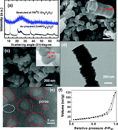
Fig. 1(a) exhibits the XRD patterns of the as-prepared and quenched samples. The as-prepared sample shows the presence of a (SnHPO4)2·H2O phase but after quenching at 600 °C, the sample transformed into an amorphous phase. An inductively coupled plasma–mass spectroscopy (ICP-MS) analysis of the quenched sample confirmed a Sn1.99P2O7 phase, and therefore water loss led to the formation of the Sn2P2O7 phase, according to (SnHPO4)2·H2O → Sn2P2O7 + 2H2O. Fig. 1(b) and (c) show the SEM images of the as-prepared and quenched samples at 600 °C from which it is seen that the as-prepared sample consists of stacked nanodisks in which each nanodisk has a thickness and diameter of ∼20 nm and ∼250 nm, respectively. Also, note that even after the quenching process the pristine octahedral shape of the nanodisk appears to be maintained.
 | ||
| Fig. 1 (a) XRD patterns of as-prepared and quenched nanodisks at 700 °C. (b, c) SEM images of as-prepared and quenched nanodisks at 700 °C (insets: expanded images of b and c). (d) TEM image of the quenched nanodisk where white spots indicate the mesopores. (e) Expanded image of (d) where red circles indicate the mesopores and the white circle indicates a possible crystalline domain. (f) N2 isotherm of the quenched sample. | ||
Fig. 1(d) and (e) show TEM images of the stacked nanodisks while randomly distributed mesopores with a diameter of <4 nm in the amorphous matrix can be observed. However, a lattice fringe that is indicated by the white circle shows the possible presence of the crystalline phase, although its XRD pattern shows a dominant amorphous phase. The N2 adsorption–desorption isotherms of the annealed samples in Fig. 1(f) show the typical curves that are observed in aggregated layered materials with irregular slit-like pores24 while the Brunauer–Emmett–Teller (BET) surface area is found to be 38 m2 g−1.
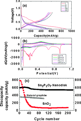
Fig. 2(a) exhibits the voltage profiles of the porous stacked nanodisks after 1, 2, 50, 100 and 220 cycles between 0 and 1.2 V. The first discharge capacity (lithium extraction) is found to be 600 mA h g−1 with a coulombic efficiency of 68%. The decomposed Sn2P2O7 led to amorphous Li3PO4 and LiPO3 matrix phase, according to 12.8Li + Sn2P2O7 → 2Li4.4Sn + Li3PO4 + LiPO3 ↔ 8.8Li + 2Sn + Li3PO4 + LiPO3.23 Compared to the SnO2 nanoparticles (ESI 1†), the coulombic efficiency of the nanodisks was improved by 28% in spite of the BET surface area being similar to each other (SnO2 was 43 m2 g−1).
 | ||
| Fig. 2 (a) Voltage profiles of the quenched nanodisks in a coin-type half cell between 0 and 1.2 V at 0.5 C rate (= 350 mA g−1) after 1, 20, 50, 100, 220 cycles. (b) Differential curves of (a). (c) Discharge capacity (after lithium removal) vs. cycle number in nanodisk. References are natural graphite and SnO2 nanoparticles. | ||
This means that the amorphous Li3PO4 and LiPO3 matrix phase is less reactive with the electrolytes than the Li2O matrix of the SnO2. The discharge capacity of the nanodisk anode gradually increased and reached a maximum value of 620 mA h g−1 after 20 cycles, after which it slowly decreased to 547 mA h g−1 after 220 cycles, showing a 91% capacity retention. Compared with natural graphite (pitch-coated), the overall discharge capacity of the nanodisks (after lithium extraction) during cycling was maintained as high as >200 mA h g−1. In terms of coulombic efficiency, its value was increased to 99% after two cycles, which was identical to that of natural graphite (see ESI 2†). Similar crystalline Sn2P2O7 (obtained by heating SnHPO4 to 550 °C) exhibited an initial charge capacity of 519 mA h g−1, which decreased rapidly to 148 mA h g−1 after 30 cycles.27 On the other hand, amorphous Sn–P–B–O composites lost 50% of their pristine capacity after 45 cycles.12
The differential capacity plots in Fig. 2(b) of the coin-type half-cell that contained nanodisks were constructed from the corresponding cycling curves in Fig. 2(a). The peaks at around 0.2 and 0.7 V are lithium insertion/extraction reactions associated with the lithium–tin alloy phases of different compositions.26 As the differential capacity plots are sensitive detectors of change in the voltage profiles from cycle to cycle, the constancy of the plots is indicative of the good reversibility of the electrode material in repetitive charge and discharge operations. However, maintaining broad peaks out to 220 cycles indicates that the tin nanoparticles were confined in the matrix without growing into large clusters. This observation contrasts with that of the tin and tin oxide composite glasses, which were smooth for the first six cycles but gave strong sharp peaks after 15 cycles, indicating the formation of large tin clusters.12
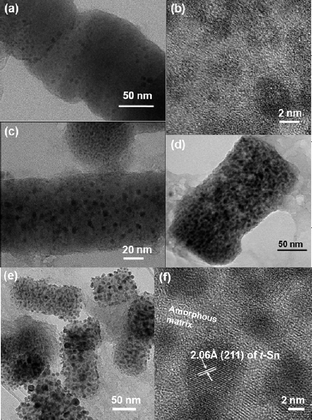
On the other hand, the SnO2 nanoparticles exhibited rapid capacity decay to 80 mA h g−1 only after 40 cycles (ESI 3†). In order to understand the differences in the capacity retention, nanodisk electrodes after the 1st, 50th, 100th and 220th cycles were extracted and TEM analyses were carried out, as shown in Fig. 3. After the 1st cycle, the pores in the nanodisks collapsed, and the amorphous nanoparticles with a size of ∼2 nm were embedded in the nanorod-shaped amorphous matrix, which was believed to be Li3PO4 and LiPO3. After 50 cycles (Fig. 3(e)), such nanoparticles grew to 5 nm. In these conditions, restricted electronic and Li ion conducting pathway between the tin atoms may occur, as proposed by Kim et al.25 and therefore, the gradual capacity increase of the nanodisks may occur until tin atoms moved over a greater distance in order to aggregate to a certain size, and thus the distance between the Sn clusters became short enough to produce percolation pathways for conduction. Similar behaviour was observed in mesocellular foam tin phosphates.25 After 100 cycles, without the particle size changing, the Sn nanoparticle population significantly increased and covered the rectangular-shaped matrix particles.
 | ||
| Fig. 3 Ex situ TEM images of nanodisks after the 1st cycle (a and b), after 50 cycles (c), after 100 cycles (d) and after 220 cycles (e and f); (f) is an expanded image of (e). | ||
Even after 220 cycles, while some particles grew to 10 nm, most of them appeared to be confined to 5 nm. In addition, the rectangular shape was sustained and all the nanoparticles became encapsulated in the rectangular rod-shaped matrix. On the other hand, SnO2 nanoparticles that had a particle size of ∼10 nm were pulverized after the 20th cycle (ESI 4b†). The HREM image (ESI 4c†) shows the formation of an amorphous layer on the Sn particles, which is believed to be the Li2O matrix. However, we could not find the Sn nanoparticles that were dispersed in the matrix. After 100 cycles (ESI 4d and e†), the particles were severely pulverized and the Sn particle size was ∼5 nm.
Similar to SnO2, Sn–P–M–O composites showed a rapid capacity fade and their capacity retention was below 40% after 40 cycles.1,22,27,28 Although there was no description of the particle sizes of these materials, the methods described in these studies resulted in bulk particles. For comparison, bulk amorphous Sn2P2O7 particles showed a rapid capacity fade after 40 cycles, and pristine 5 μm-sized particles were completely pulverized to 10 nm-sized particles (ESI 5†). We believe this difference could be due to the surface area to volume ratio that increased dramatically when the size decreased to the nanometre range, and that any dislocations induced by the volume change during lithium alloy and dealloy may have been quickly drawn to the surface.29,30 A similar result was also observed in SnHPO4 nanoparticles that had a mesocellular form structure.25
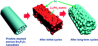
Overall, Fig. 4 shows schematic views of the morphology evolution of the stacked porous tin phosphate (Sn2P2O7) nanodisks upon lithium reaction. Porous nanodisks with a thickness of 20 nm led to confinement of the Sn nanoparticle growth in the LixPOy matrix particle pulverization. Even after extended cycles, Sn nanoparticles grew but were confined in the matrix of which the size was similar to that after initial cycles.
 | ||
| Fig. 4 Schematic view of morphology evolution of pristine stacked porous nanodisks. | ||
In conclusion, stacked amorphous Sn2P2O7 nanodisks demonstrated excellent reversible capacity and capacity retention, even after 200 cycles. In the nanodisks, the matrix phases that consisted of lithium phosphates (Li3PO4 and LiPO3) as a reaction product could play a role as a “glue” that keeps the Li–Sn particles mechanically connected during the large volume changes of Sn during the alloying/dealloying processes. One of the biggest concerns of the lithium reactive metals relates to the volume change during the lithium alloy and dealloy process. However, the fact that the pristine nanodisk particle size was retained without pulverization even after extended cycling indicated no problem with the mechanical stability of the nanodisk anodes.
This research was supported by the Converging Research Center Program through the National Research Foundation of Korea (NRF) funded by the Ministry of Education, Science and Technology (2009-0082083).
Notes and references
- I. A. Courtney and J. R. Dahn, J. Electrochem. Soc., 1997, 144, 2045 CAS.
- S. Panero, G. Savo and B. Scrosati, Electrochem. Solid-State Lett., 1999, 2, 365 CrossRef CAS.
- J. Zhu, Z. Lu, Z. S. T. Aruna, D. Aurbach and A. Gedanken, Chem. Mater., 2000, 12, 2557 CrossRef CAS.
- S. C. Nam, T. H. Kim, W. I. Cho, B. W. Cho, H. S. Chun and K. S. Yun, Electrochem. Solid-State Lett., 1999, 2, 9 CrossRef CAS.
- C. Kim, M. Noh, M. Choi, J. Cho and B. Park, Chem. Mater., 2005, 17, 3297 CrossRef CAS.
- M. Winter and J. Besenhard, Electrochim. Acta, 1999, 45, 31 CrossRef CAS.
- S. Han, B. Jang, T. Kim, S. M. Oh and T. Hyeon, Adv. Funct. Mater., 2005, 15, 1845 CrossRef CAS.
- W. Lou, Y. Wang, C. Yuan, J. Y. Lee and L. A. Archer, Adv. Mater., 2006, 18, 2325 CrossRef CAS.
- Y. Wang, F. Su, J. Y. Lee and X. S. Zhao, Chem. Mater., 2006, 18, 1347 CrossRef CAS.
- D. Deng, M. G. Kim, J. Y. Lee and J. Cho, Energy Environ. Sci., 2009, 2, 818 RSC.
- G.-A. Nazri and G. Pistoia, Lithium Batteries Science and Technology, Kluwer, Boston, MA, 2004 Search PubMed.
- I. A. Courtney, W. R. Mckinnon and J. R. Dahn, J. Electrochem. Soc., 1999, 146, 59 CrossRef CAS.
- Y. Wang and J. Y. Lee, J. Phys. Chem. B, 2004, 108, 17832 CrossRef CAS.
- Y. Wang, H. C. Zeng and J. Y. Lee, Adv. Mater., 2006, 18, 645 CrossRef CAS.
- Y. Wang, J. Y. Lee and H. C. Zeng, Chem. Mater., 2005, 17, 3899 CrossRef CAS.
- M. G. Kim and J. Cho, Adv. Funct. Mater., 2009, 19, 1497 CrossRef CAS.
- M. S. Park, G.-X. Wang, Y.-M. Kang, D. Wexler, S.-X. Dou and H.-K. Liu, Angew. Chem., Int. Ed., 2007, 46, 750 CrossRef CAS.
- F. Chen and M. Liu, Chem. Commun., 1999, 1829 RSC.
- H. Kim and J. Cho, J. Mater. Chem., 2008, 18, 771 RSC.
- D.-F. Zhang, L.-D. Sun, J.-L. Yin and C.-H. Yan, Adv. Mater., 2003, 15, 1022 CrossRef CAS.
- Y. Idota, T. Kubota, A. Matsufuji, Y. Maekawa and T. Miyasaka, Science, 1997, 276, 1395 CrossRef CAS.
- I. A. Courtney and J. R. Dahn, J. Electrochem. Soc., 1997, 144, 2943 CAS.
- Y. W. Xiao, J. Y. Lee, A. S. Yu and Z. L. Liu, J. Electrochem. Soc., 1999, 146, 3623 CrossRef CAS.
- K. S. Sing, D. H. Everett, R. A. W. Haul, L. Moscou, R. A. Pierotti, J. Rouquerol and T. Siemieniewska, Pure Appl. Chem., 1985, 57, 603 CrossRef CAS.
- E. Kim, M. G. Kim and J. Cho, Electrochem. Solid-State Lett., 2006, 9, A311 CrossRef CAS.
- H. Kim, G.-S. Park, E. Kim, J. Kim, S.-G. Doo and J. Cho, J. Electrochem. Soc., 2006, 153, A1633 CrossRef CAS.
- M. Behm and J. T. S. Irvine, Electrochim. Acta, 2002, 47, 1727 CrossRef CAS.
- M. L. E. Moubtassim, J. I. Corredor, J. L. Tirado and C. P. Vicente, Electrochim. Acta, 2001, 47, 489 CrossRef.
- J. Graetz, C. C. Ahn, R. Yazami and B. Fultz, Electrochem. Soild-State Lett., 2003, 6, A194 Search PubMed.
- H. Kim and J. Cho, Nano Lett., 2008, 8, 3688 CrossRef CAS.
Footnote |
| † Electronic supplementary information (ESI) available: A typical experimental procedure for the samples, and XRD, SEM, TEM images of SnO2 and reference Sn2P2O7 anodes. See DOI: 10.1039/b924381j |
| This journal is © The Royal Society of Chemistry 2010 |
