 Open Access Article
Nanoscale designing of metal organic framework moieties as efficient tools for environmental decontamination
Indu
Sharma†
a,
Jaspreet
Kaur†
b,
Gargi
Poonia
a,
Surinder Kumar
Mehta
 *a and
Ramesh
Kataria
 *a
*a
aDepartment of Chemistry, Centre of Advanced Studies in Chemistry, Panjab University, Chandigarh-160 014, India. E-mail: skmehta@pu.ac.in; rkataria@pu.ac.in
bSchool of Basic Sciences, Indian Institute of Information Technology (IIIT), Una-177 209, India
First published on 15th June 2023
Abstract
Environmental pollutants, being a major and detrimental component of the ecological imbalance, need to be controlled. Serious health issues can get intensified due to contaminants present in the air, water, and soil. Accurate and rapid monitoring of environmental pollutants is imperative for the detoxification of the environment and hence living beings. Metal–organic frameworks (MOFs) are a class of porous and highly diverse adsorbent materials with tunable surface area and diverse functionality. Similarly, the conversion of MOFs into nanoscale regime leads to the formation of nanometal–organic frameworks (NMOFs) with increased selectivity, sensitivity, detection ability, and portability. The present review majorly focuses on a variety of synthetic methods including the ex situ and in situ synthesis of MOF nanocomposites and direct synthesis of NMOFs. Furthermore, a variety of applications such as nanoabsorbent, nanocatalysts, and nanosensors for different dyes, antibiotics, toxic ions, gases, pesticides, etc., are described along with illustrations. An initiative is depicted hereby using nanostructures of MOFs to decontaminate hazardous environmental toxicants.
1. Introduction
The rapid upsurge of pollutants is raising a red alert for the healthy living of the species present worldwide. The presence of organic waste, various toxic gases from industries (CO2, SO2, NO2, H2S, etc.), dyes from textile industries, oils, and detergents in the environment are endangering flora and fauna.1 About 80% of 1.3 × 10⁵ tons of active dyestuff produced is used in the textile industries of India, which is a matter of great concern.2 Moreover, heavy metals, having a high atomic weight and 5 times higher density than water, contain a high degree of toxicity. These heavy metal ions including Hg, Pb, Cr, and Cd above their safe threshold may cause serious diseases including acute or chronic poisoning by their exposure to food, air, and water.Along with heavy metal ions, certain pharmaceuticals, pesticides, antibiotics, herbicides, and insecticides are captivating the research interest due to their adverse impact on the ecosystem. These contaminants degrade soil and water quality by mixing into them. Various personal care products (PCPs), such as diclofenac, musks, carbamazepine, ibuprofen, and bisphenol A, were listed as emerging components according to the priority pollution list by EU (European Union) and USEPA (United States Environmental Protection Agency) in 2007.3 Several gases released from domestic, agricultural, and industrial fields are responsible for climate change by increasing the ocean and earth's temperature.4 Emerging contaminants (ECs), also known as micropollutants, are a diverse group of anthropogenic substances that are frequently found in water but have only recently been recognized as significant contaminants in water.5 The generation of these pollutants has increased from one million to 500 million tonnes annually throughout the world.6 Nevertheless, many ECs have been linked to known or suspected negative effects on human health and the environment, as shown in Fig. 1(a).7,8Fig. 1(b) outlines the various ECs posing threats to the human environment. These pollutants primarily come from industrial, agricultural, and municipal wastewater as well as industrial smoke because water and air may easily migrate from one site to another. Fig. 1(c) depicts the life-cycle distribution of emerging micropollutants from the perspective of sources to receptors.
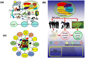 | ||
| Fig. 1 (a) Subsequent distribution of arising pollutants from sources to the receptors, (b) schematic representation of the sources of various pharmaceutical drugs, their prime consumers, persistency and their major outcomes, and (c) adversity of various ECs for human beings and environment (reproduced with permission from ref. 7. Copyright 2019 Elsevier). | ||
The ecological balance is based upon the interaction of society with the environment. The behavior of society with the environment majorly influences the health of the ecosystem. Several responses given by our society to the environment using the above-described contaminants are accompanied by climate change, toxicity in air, soil infertility, adverse aquatic environment, and so on. There is a crucial need to overcome these challenges as there is no question of our existence if we are prone to an endangered life full of such environmental threats. To date, there are numerous researches done in the same field.
MOFs, metal centers linked with various multitopic organic linkers have currently been classified as an important group consisting of porous compounds. MOFs can possess various features, e.g., large surface area, enhanced pore volume, linking abilities, and tunable structure architecture. A zeolite-imidazole-based family of MOFs termed ZIF (Zeolite Imidazole Framework) family consist of metal centers Fe, Cu, Co, etc., surrounded by imidazole connectivity. Moreover, UIL, HKUST, MIL, etc., are also some of the families of MOFs accompanying a large number of MOFs with them.9 To restrict various metal ions in the ZIF9 framework, a novel space-confined synthesis technique is provided.10 By performing high-temperature pyrolysis, a variety of carbon compounds generated from ZIF9 that exhibit high capacitance and high rates of charge transfer were produced. Capacitive deionization (CDI) encourages the creation of carbon materials produced by MOF for use in the domains of water and energy treatment, which have a wide range of potential applications. MOFs are in demand nowadays for their extended applicability in the field of environmental decontamination through the use of their gas sensing, catalytic, and adsorptive properties along with luminescent sensing properties.11 In addition, MOF-based biosensors and fluorescent sensors have been developed nowadays due to various naturally-occurring transitions in between them.12
Despite having many advantageous features, there occur some substantial drawbacks, e.g., poor mechanical strength and electrical conductivity, slow degradation, and less resistance toward water and light.9 Hence, to improve the abovementioned properties, it is necessary to convert MOFs to their corresponding nanostructures (nanoparticles/nanocomposites). Various carbon-based hybrid nanocomposites have drawn the attention of researchers for environmental decontamination. CNT (carbon nanotubes) have evolved as an effective adsorbent over activated carbon, fly ash, and zeolite due to their tunable adsorption capacity and surface chemistry. Their usage is limited due to their cost; hence, nanocomposites are made using MOFs with carbon-based materials such as CNTs, graphene, and rGO. Carbon nanocomposites can improve the mechanical strength and chemical stability of MOFs. The surface area reported from BET analysis was 7000 m2 g−1, which was much more than that of bare MOFs.13 Similarly, the encapsulation of metal NPs (Ag, Pt, Pd, Fe, etc.) and metal oxide NPs have also been done by researchers, e.g., Bi2O3@HKUST-1, ZnO@ZIF-8, UiO-66@WO3, and Fe3O4@MIL(100) as photocatalysts.14 Semiconductors such as TiO2, g-C3N4, CdSe, GaP, ZnS, and CdS also evolved in this field to combine the properties of MOFs and semiconductors for their better photocatalytic abilities. This is due to the facile transfer of charges, water, and light through these nanocomposites as compared to their bare constituents.15
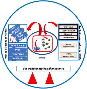
Herein, various MOF nanostructures including nanoparticles and nanocomposites have been reviewed as environmental decontaminants. This present review emphasizes various ex situ and in situ methods of synthesis of MOF nanocomposites with carbon materials, metal nanoparticles (MNPs), metal oxides, and semiconductors. The direct synthesis of MOF nanoparticles using various methods including solvothermal, ultrasonic, electrochemical, and microwave-assisted has also been illustrated here. MOF nanostructures were employed as nanocatalysts, nanosensors and nanoadsorbents for different toxic ions, gases, dyes, antibiotics, and pesticides. Relevant classification, explanation, and suitable illustrations for each synthetic strategy and applicability of NMOFs are described in this paper. The outline of the recount has been depicted in Scheme 1.
2. Synthesis
2.1. Direct synthesis of MOF nanoparticles (MOF NPs)
The assembly of metal ions and ligands to form MOFs depends upon the solvents, reaction time, and temperature. Catalytic site production for the reaction is influenced by the solubility of reactants and temperature while the final morphology of the NMOFs is decided by the affinity between the ligands and metal centers. The better the solubility of the reacting species, the more will be the emergence of nanoscale units. Template method or using emulsions can also promote the formation of nanoscale MOFs by limiting the size of self-assembling species. Herein, some methods are described to directly synthesize nanoscale MOFs, namely, microwave assistance, solvothermal process, electrochemical synthesis, and ultrasonic synthesis.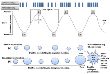 | ||
| Fig. 2 Mechanism showing cavitation phenomenon: (a) stable cavitation and (b) transient cavitation (reproduced with permission from ref. 16. Copyright 2019 Elsevier). | ||
Chalati et al. synthesized nanoparticles of a porous and flexible iron-based MOF, i.e., MIL-88A using various synthesis schemes. The yield and particle size of the MOF were analyzed using static hydrothermal/solvothermal synthesis, ultrasonic synthesis, dynamic ambient pressure synthesis, and microwave-assisted synthesis conditions. Only microwave-assisted hydrothermal synthesis proved to be the most rapid and convenient method to control the size along with larger yields of monodispersed nanoparticles, i.e., size less than 100 nm and polydispersity index [PDI] less than 0.20. While using ultrasonic synthesis, a mediocre yield of monodispersed MOF nanoparticles was obtained with a size of 100 nm and PDI of 0.24.20 Further, flower-like nanostructures of Ta-MOF have also been successfully achieved using ultrasound-assisted microwave irradiation.21 There is no evidence of particle agglomeration or aggregation when employing the ultrasound-assisted method since the sample produced by this approach has a more consistent morphology than the sample produced by the microwave method. However, the microwave technique results in some particle aggregation, which can increase the Ta-MOF sample's diameter.
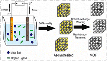 | ||
| Fig. 3 Schematic diagram of the electrochemical synthetic procedure of MOFs (reproduced with permission from ref. 27. Copyright 2020 Elsevier). | ||
Zhang et al. synthesized nanoparticles of a Zn-based Iso-Reticular MOF (IRMOF-3) having Zn4O as a secondary building unit and NH2–H2 BDC (2-aminoterephthalic acid) as linkers. The synthesis was completed within 3 h using the electrochemical method. After the passage of 3 h and at 6 V voltage, the synthesized NMOFs were found to have a size less than 200 nm. The products were amorphous when pure DMF was taken as the solvent.
After adding ethanol with DMF slowly, the XRD pattern of NMOFs was found to match the simulated pattern. The reason behind this was that the nucleation rate was affected by ethanol. The concentration of ethanol should be kept low, keeping in view that the concentration of reactants should be comparable. Moreover, they also synthesized polyhedral NMOF (UiO-66-NH2) of size 65 nm with a reaction time of 1 h and at 4 V voltage. The solvent used was DMF and acetic acid in a ratio of 52![[thin space (1/6-em)]](https://www.rsc.org/images/entities/char_2009.gif) :
:![[thin space (1/6-em)]](https://www.rsc.org/images/entities/char_2009.gif) 8. Although this strategy takes a few hours for the reaction to complete but it proves to be cost-effective and occurs at normal pressure and temperature for the direct synthesis of NMOFs.19–28
8. Although this strategy takes a few hours for the reaction to complete but it proves to be cost-effective and occurs at normal pressure and temperature for the direct synthesis of NMOFs.19–28
Behrens et al. used the solvothermal method that studied the size regulation of Zr-MOF NPs by regulating the reagent concentration. After adding different ratios of benzoic acid, the size of Zr-MOFs could be regulated. With the enhancement in benzoic acid concentration, the aggregation of smaller particles to single nanocrystals takes place gradually, as revealed by scanning electron microscopy (SEM) analysis. In the end, good crystal shapes with 200 nm size were obtained after using 30 times the equivalent of benzoic acid to ZrCl4.30
TMU-34(-2H) MOF powder was synthesized by the sonochemical method shown in Fig. 4.31 The pink powder was characterized using IR spectroscopy, X-ray powder diffraction, scanning electron microscopy, and N2 adsorption.
 | ||
| Fig. 4 (a) Stick cap model and (b) space-filled model showing the interconnected pores for the representation of TMU-34(-2H) (reproduced with permission from ref. 31. Copyright 2017 Elsevier). | ||
For the morphological modification, the initial concentration of reagents, molar ratio of pyridine, sonication time, and power were optimized. The SEM images of the synthesized compound after 60, 80, and 100 min were recorded, as shown in Fig. 5. The outcomes indicated that TMU-34(-2H) exhibits a uniform plate-like morphology at 360 W power and 60 min sonication time with pyridine as the modulator.
 | ||
| Fig. 5 SEM images of sonochemically synthesized TMU-34(-2H) after (a) 60 min, (b) 80 min, and (c) 100 min (reproduced with permission from ref. 31. Copyright 2017 Elsevier). | ||
Qiu et al. used an ultrasonic technique to synthesize nanoparticles of Cu-BTC [Cu(II)-benzene-1,3,5-tricarboxylate] MOF within the size range from 50 to 100 nm. Within 10 min, the yield of MOF NPs was found to be 78.2% while reaching 85.3% with the increase in reaction time. The size-controlling parameters were the addition of inhibitors, dilution, and a decrease in temperature.32 Using the ultrasonic method, Zn(II)-based nanoparticles of MOF (TMU-4) with a reaction time of 5 to 10 min and a size range of 50 to 100 nm were fabricated by Morsali et al. Most optimized and uniform nanostructures were obtained after 90 min with a pH regulator concentration of 0.02 mol L−1. The Zn-MOF NPs were facile to synthesize at room temperature. They include some features including photodegradability and high uniformity.33
2.2. In situ incorporation of NPs in MOFs
MOFs have a vast variety of applications including adsorption, catalysis, sensing, gas storage, gas–vapor separation, and biomedical imaging. The conversion of MOFs to their nanostructures can be an efficient tool to improve their morphology, surface area, porosity, and uniformity, and hence enhances their applicability. MOF nanoparticles can be synthesized by various methods. Among them, in situ encapsulation is one of the efficient methods that can be adopted due to its low complexity and lesser reaction time. This process provides us with more thermostability, particularly MOFs. In comparison to other synthetic strategies, this method provides effective and more guest component-loading over the host MOF. The guest components may include metal oxide and metal nanoparticles (MNPs). There are various in situ methods for the synthesis of MOF nanoparticles. Some of them are solvothermal, hydrothermal, electrospun, microwave synthesis, the deligandation process, polymerization, spin coating, and thermal crosslinking.Herein, we have discussed some of the methods for the in situ synthesis of MOF nanostructures, e.g., solvothermal method, hydrothermal method, and electrospun method.34
However, during the growth of the crystals, chemical and structural defects are frequently observed, which can be tuned by altering the crystal growth rate of the solvothermal process. In addition, the crystal growth rate can be enhanced by adjusting the pressure, reaction temperature, growth temperature, crystal orientation, solvent concentration, and hydrodynamics.38 As a result, optimizing the parameters of growth rate allows solvothermal synthesis to control the morphology of the crystals derived. Miyamoto et al. used a solvothermal method for the growth of UiO-66 films using monocrystalline growth of UiO-66 nanocrystals. Adding acetic acid and water influenced the synthesis of a highly oriented film of UiO-66. Acetic acid controlled the crystal growth by acting as a modulator while water accelerated Zr precursor hydrolysis and thereby enhanced UiO-66 intergrowth without influencing their orientation. The reported UiO-66 film containing excellent orientation of crystals displayed higher chemical stability than that of MOF(UiO-66) powder. Further, SEM images revealed the highly-oriented monocrystalline growth of the film. Based on chemical stability and high orientation, these films were expected to show excellent applicability compared to bare MOF UiO-66.39
The hydrothermal method is now a widely used process in the fabrication of a broad range of materials, including bulk crystals and size-controlled and morphological nano and fine particles. When compared to more conventional methods of processing materials, the hydrothermal method offers numerous advantages.
Xu et al. reported the successful fabrication of Fe-MOF/Au-8/FF nanorods using the hydrothermal strategy shown in Fig. 6. This method involves the combination of an Fe foam template with electrodeposition. The nanorods were accompanied by well-resolved lattice fringes after the electrodeposition of Au. Fe-MOF, after in situ growth on the FF surface, undergoes electrodeposition of Au on the Fe-MOF/FF surface. This nanocomposite possesses enhanced activity due to increased conductivity, increased electrochemical activity for specific areas, and oxygen evolution (OER) and hydrogen evolution (HER).44
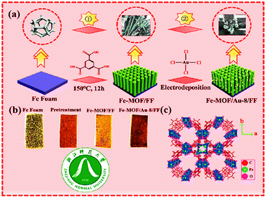 | ||
| Fig. 6 (a) Schematic illustration of Fe-MOF/Au-8/FF; (b) process chart of the color change of the synthesized sample; (c) crystal structure of Fe-MOF (along c-axis) (reproduced with permission from ref. 44. Copyright 2022 Elsevier). | ||
Aslam et al. devised the utilization of a step-in situ hydrothermal strategy for the efficient synthesis of Fe3O4@MIL-100(Fe) nanoparticles. Fe3O4 not only provides a magnetic core for nanocomposite growth but also provides Fe3+ for the heterogeneous growth of MOF MIL-100(Fe). The prepared nanocomposites showed enhancement in pore volume and surface area with the special addition of a superparamagnetic feature. These features make this nanocomposite possess a wide application field rather than its bare components, i.e., Fe3O4 and MIL-100(Fe). In this work, methylene blue (MB) adsorption was shown by this nanocomposite for depolluting water. The schematic representation of the work has been shown in Fig. 7.45
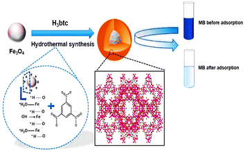 | ||
| Fig. 7 Schematic representation of the in situ one-step hydrothermal synthesis of Fe3O4@MIL-100(Fe) core–shell magnetic microspheres (reproduced with permission from ref. 45. Copyright 2017 Elsevier). | ||
Further, in the same field, a one-pot hydrothermal methodology was adopted to synthesize a composite consisting of cobalt oxide nanocubes dispersed over the sheet of Co-MOF (Co3O4@Co-MOF).46 The composite was found to show enhancement in alkaline stability, increment in redox ability, and an expeditious increase in the capacitance value. Moreover, the integration of metal oxide with the MOF did not alter the original identity of the MOF but enhanced its applicability.
Al-Baadani et al. demonstrated the use of the in situ electrospun method for the fabrication of Zr-based MOF (ZIF-8) nanofibers. Herein, the embedment of the polycaprolactone/gelatin (PG)-blended membrane was done with alendronate-loaded ZIF-8 (Aln/ZIF-8). Various compositions of ZIF-8 were taken, i.e., 0.25%, 0.5%, and 1%. SEM analysis revealed that the nanofibers are uniform in size and are randomly distributed without the bead defect. It further suggested the successful synthesis of nanofibers (PG/Aln-ZIF-8) with good mechanical strength.48
2.3. Ex situ incorporation/composites of NPs in the MOFs
It is necessary to refine the properties of MOFs for enhancing the quality of application. Eventually, various strategies to form MOF nanocomposites have been proposed, where some external entities in addition to MOF proceed toward the formation of nanocomposites of MOF. Herein, ex situ methods to form MOF nanocomposites have been detailed, including MOF loading by metal nanoparticles (MNPs), incorporation of semiconductor nanosheets into MOF, and decoration of MOFs by r-GO.There are many methods of ex situ formation of MOF nanocomposites which can be broadly divided into three parts: (1) metal nanoparticle [MNP] loading on MOF, (2) embedding semiconductors into MOF, and (3) adorning of MOF by carbon materials.
After the synthesis of various nanocomposites, certain investigations become important to ensure the proper embedment of MNPs within the MOFs. These include some characterization method listed below to reveal the actual relationship between metal-loaded MOF, i.e., nanocomposites, and unloaded MOF. The characterizations include – (a) TEM/SEM/PXRD to ensure the maintenance of the actual shape and crystallinity of MOFs; (b) XPS to examine the oxidation state of MNPs; (c) HRTEM, STEM, PXRD, and EDX to ensure the size and distribution of MNPs, and (d) a single crystal tilt experiment or tomographic reconstruction to locate the position of MNPs in the MOFs.50
After MNPs loading, significant amplification occurs in the catalytic efficiency of the produced nanocomposites. The size regime in the nanorange has high surface density and very dense uncoordinated sites. Further, in photocatalytic reactions, metal loading greatly supports visible light absorption using localized surface plasmon resonance (LSPR) upon exposure to visible light irradiation.
Pd@UiO-66(NH2) was fabricated by the simple mixing of MOF, PdCl2, NaI, and PVP in an autoclave, followed by heating. The introduction of Pd causes an increase in visible light absorption intensity for MOF. The prepared nanocomposites Pd@UiO-66(NH2) displayed greater catalytic efficiency than bare MOF UiO-66(NH2) during the reduction of Cr(VI) and photodegradation of dyes after visible light irradiation. The enhanced photoactivity of Pd@UiO-66(NH2) is due to the combined effect of the more efficient separation of the electron–hole pair and increased surface area. The Pd NPs take up the excited electrons from the MOF and hence reduce the Cr(VI) double solvent approach, followed by the encapsulation of Pd NPs in the pores of MOF.
Apart from photocatalysis, enzymatic activity-based applications also show better results in the case of such nanocomposites as compared to simple MOFs. Wang et al. used Pt NPs confinement in MOF Uio-66 with a different weight percentage of Pt-entitled Pt/Uio-66-1%, Pt/Uio-66-3%, and Pt/Uio-66-6% by varying amounts of K2PtCl4.51 TEM, SEM, and PXRD ensured the successful insertion of Pt NPs into the pores of MOF along with the retention of the same crystal structure, as depicted in Fig. 8.
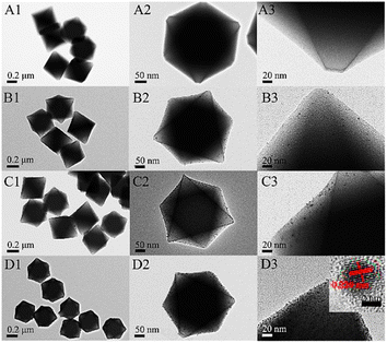 | ||
| Fig. 8 TEM images at low and high magnifications of UiO-66 (A), Pt/UiO-66-1% (B), Pt/UiO-66-3% (C), and Pt/UiO-66-6% (D). The inset in (D3) is the HRTEM of the Pt particle (reproduced with permission from ref. 51. Licensed under Creative Commons Attribution 4.0 International License (https://creativecommons.org/licenses/by-nc-nd/4.0/) © 2021 ACS Omega). | ||
The embedment of Pt content in Uio-66 enhanced the enzymatic activity of Uio-66 in a specific trend as 6% Pt > 3% Pt > 1% Pt. Hence, the colorimetric sensor for the detection of glucose using the Pt/UiO-66 nanocomposite would not be able to sense as the zirconium-based MOF was unable to respond to enzymatic action.
Guo et al. prepared MOF nanocomposites with metal oxide semiconductor TiO2 using a two-step process. The prepared photoanodes of NH2-MIL-125/TiO2 facilitated the transfer tendency of the electron–hole pairs along with the promotion and protection for photocathodic 304SS when irradiated under visible light. This TiO2 nanotube-based heterojunction avoids the electron–hole pair recombination, proceeding further to achieve efficient photocathodic protection.52 Zhao et al. devised a nanocomposite heterostructure using semiconductor nanorods CdS and ZIFs that is capable of enhancing the current density of CdS with the simultaneous lowering of the HER overpotential. Further, a variety of heterojunctions with different doped metals were fabricated CdS–ZnM–ZIF (M = Cu, Ni, Co) to study photocatalytic hydrogen generation. The nanocomposites had the properties of inhibiting the recombination of charge carriers and hence promoting the transfer efficiency by separating the charges.53 The effective energy transfer from a light-harvesting framework (IRMOF-3) enclosing each semiconductor quantum dot (QD) as a surface modification boosted their photoluminescence. The direct growth of IRMOF-3 crystals without any intermediary layer, such as polymers, on the QD surface is shown (Fig. 9).54 Fluorescence lifetime measurement and steady-state excitation spectra measurement both supported the reported photoluminescence amplification caused by IRMOF-3's light harvesting.
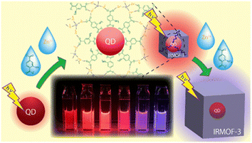 | ||
| Fig. 9 Schematic illustration for the QD based surface modification of IRMOF-3 (reproduced with permission from ref. 54. Licensed under Creative Commons Attribution 4.0 International License (https://creativecommons.org/licenses/by-nc-nd/4.0/) © 2021 ACS). | ||
Similarly, Akbarzadeh et al. synthesized the nanocomposite Ag3O4/r-GO-/Cu-MOF, which successfully degraded AB92 dye with improved efficiency. The improved activity of the nanocomposite was due to its increased surface area, efficient separation, and transport of charge carriers. The surface area calculated from BET was about 5.63 m2 g−1.56 Nanocrystals of a Co-based MOF, ZIF-67, were synthesized by Xia et al. Further, after pyrolyzing the produce, nitrogen-doped carbon nanopolyhedrons were fabricated.
The carbonized MOF NPs were found to show ORR (oxygen reduction reaction) activity similar to the Pt/C catalyst. Zou and co-workers studied the effect of particle size of nanoMOF and the corresponding derived material on the catalytic activity. They synthesized ZIF-67 in various conditions to achieve different particle sizes ranging from bulk to 300 nm. The polyhedral morphology of the MOF nanoparticles was retained in the MOF-derived carbon materials (MDCs) by carefully choosing the pyrolysis temperature under Ar atmosphere, which is ascertained from TEM. The synthesized carbonized MOF NPs have a BET surface area of 386 m2 g−1. The ZIF NPs had narrower pore size distribution of 0.9 nm, while after carbonization, mesopores in the range of 2–5 nm and pores with a size greater than 26 nm were formed. This study put forward a small particle size having more exposed and easily accessible active sites for a fast electron transfer process.57
Moreover, nowadays, MOF-derived carbon-based nanocomposites are also captivating the attention of researchers. The innovative porous Fe3O4@NPC composites were successfully created by in situ formation during the thermal breakdown process utilizing Fe-MOFs as the template material.58 The Fe3O4@NPC composites, which were made up of Fe3O4 nanoparticles uniformly scattered in the ordered octahedral structure of the carbon matrix, preserved the original octahedral appearance (Fig. 10). The well-designed structure of the Fe3O4@NPC composites and the synergistic interaction between Fe3O4@NPs and NPC were credited with the exceptional performance. As a result, this work may offer a fresh perspective on the design and synthesis of materials that may effectively block electromagnetic waves.
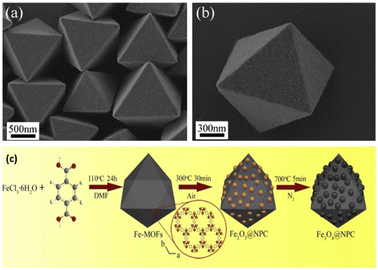 | ||
| Fig. 10 SEM images of (a) Fe-MOF crystals, (b) single Fe-MOF crystal, (c) schematic representation for the synthesis of nanocomposite Fe3O4@NPC derived from Fe-MOF. Reproduced with permission from ref. 58. Copyright 2019 Springer. | ||
3. Applications of NMOF nanomaterials
3.1. Catalysis
MOF nanomaterials have a wide range of applications. One of them is catalysis. NanoMOFs can act as efficient water/oxygen oxidizing catalysts (WOC). For example, Wang et al. described the potential of nanocrystalline Co–ZIF-9 nanomaterial as an effective water oxidation catalyst.Nanomaterials derived from MOF have prominently been used as an excellent catalyst in the adaptable catalytic process for the elimination of contaminants. MOF derivatives have a great potential for active site exposure due to their large surface areas. After the formation of nanocomposites of MOF, the retained morphology and variable pore size both help in improving the performance of the catalyst.59 Because of these advantages, compounds derived from MOF are suitable candidates for a catalytic reaction that occurs in the environment. We mainly focus on three processes: (1) photocatalysis, (2) Fenton-like catalysis, (3) persulfate (PS)/peroxymonosulfate (PMS)-activated catalysis.
With regards to physical science (thermodynamics), the light-generated species (holes/electrons) may scale back  , and holes, which are left in the valence band, will react with OH− to generate the hydroxide radical (OH˙).60 On the other hand, the holes having a strong oxidative ability can directly bring about the light oxidation of chosen impurities. These extremely active species play a vital role in photocatalytic degradation. Numerous studies have demonstrated improvement in the electronic and optical properties of photocatalysts such as extending the lifetime of diving h+/e− pairs, intensifying the photoharvesting power, and promoting the conduction of charge carriers.61,62
Wu et al. studied the performance of photodegradation of metals M (M = Au, Pd, and Pt)@MIL100(Fe) (Fe3O(H2O)2(OH)(BTC)2·nH2O (n ≈ 3.2)) concerning organic contaminants.69 These studies were done under visible light (≥420 nm) by the use of methyl orange as a dummy pollutant and oxidizer as H2O2. Expectedly, all the M@MIL-100(Fe) composites exclusively showed magnificent photodegradation activity as compared to crude MIL-100(Fe). The photocurrent and photoluminescence results showed that this enhancement is due to the addition of metal nanoparticles, which enhanced the charge transfer ability amidst M@MIL-100(Fe). In addition, among all the composites of M@MIL-100(Fe), Pt@MIL-100(Fe) showed the best photodegradation effect. This was validated through charge-carrier separation and visible light absorption data. The other upcoming pollution source is heavy metals, more seriously, through Cr(VI), which is discharged in large amounts from textile industries. Also, steel manufacturing causes a significant threat to the earth. Likewise, the nanoparticle-based MOF have shown significant charge carrier ability (Au@MIL-100(Fe) (0.1861 min−1), Pt@MIL-100(Fe) (0.5618 min−1), MIL-100(Fe) (0.1518 min−1), Pd@MIL-100(Fe) (0.2883 min−1)). Moreover, Hu et al. also used Co–Fe bimetallic MOF-derived nanocomposite (CoFe2P@mC) for the photocatalytic degradation of rhodamine B (Rh B) dye. The schematic representation is shown in Fig. 11. After the passage of 30 min, the nanocomposites achieved 99.7% degradation efficiency.70
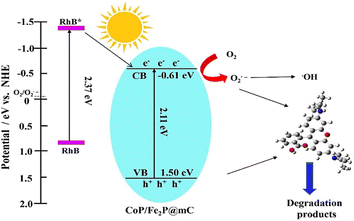 | ||
| Fig. 11 Schematic illustration of the photodegradation process of RhB over the CoP/Fe2P@mC nanocomposites (reproduced with permission from ref. 70. Copyright 2018 Elsevier). | ||
The reaction between H2O2 (cathodically produced) and metal ions on the surface of the catalyst can yield reactive OH radicals in the electro-Fenton system.72 The succeeding oxidation process can benefit from improved efficiency and lower costs associated with the consumption of H2O2 from such a reaction of H2O2 (generated in situ). In this area of research, nanomaterials derived from MO have permanent porosity, tailored texture, well-defined structure, and a huge surface area. This makes it possible to quickly develop heterogeneous catalysts for Fenton-like systems. The catalyst derived from transition metals such as Co, Cu, and Fe among the various derivative reported from MOFs, exhibit significant potential in Fenton-like heterogeneous systems.73,74
For the forward oxidation process, the synthesis of an efficient and recyclable catalyst of Fenton-like is still a crucial factor. By controlling the calcination of Fe-based MOF in 2 steps, Fe3O4/C with an octahedral shape was obtained. Interpreted nanoparticles of Fe3O4 covered with a carbon layer made of graphite provide an ample channel of solid–liquid in the mesopore, assembling the porous octahedral. Graphitic carbon's oxygen-containing functional group also give the catalyst its hydrophilic nature and ability to dissolve easily in water. For decaying the organic dye MB (methylene blue) with the assistance of H2O2, the Fe3O4/C porous octahedral demonstrates the efficient Fenton-like heterogeneous reaction and nearly 100% elimination efficiency in 1 h. In addition, a magnetic catalyst's ability to be separated by an external magnetic field maintains its activity after 10 cycles. This indicates the long-term durability and recyclability of the catalyst. The unique mesoporous structure derived from the MOF, in addition to the sacrificial role and stabilizing effect of the carbon layer made of graphite, is responsible for the excellent catalytic performance of Fenton-like synthesized octahedral Fe3O4/C. The structure with an integrated porous octahedral carbon layer made of graphite can be easily synthesized using this easy method, and the catalyst has noteworthy capability for the treatment of wastewater.
 dominate the catalytic degradation process. During the oxidation process, the breaking of the –O–O– (peroxide bond) of PS/PMS can cause SO4 to be produced, which breaks down and limits the decay or break down the molecules of pollutants into H2O and CO2, thus transforming the remaining molecules into intermediate molecules of small size.75 Nonradical (primarily electron transfer) catalytic process can be prompt to operate PS/PMS and additionally break down organic pollutants concerning carbon materials and carbon/metal hybrids. By overcoming the inertness to chemicals of the sp2 carbon (C) configuration, carbon's graphitic N atoms can cause electron transfer from the carbon atoms to the nearby graphitic nitrogen, resulting in positively charged reactive sites. Graphitization degree, i.e., the degree to which carbon atoms form closely packed hexagonal graphitic structure, N doping of C (carbonaceous) catalyst, and conductivity are primarily responsible for the effectiveness of the oxidation process of nonradicals.76
Nevertheless, the pathway of nonradicals has not been fully revealed and further in-depth studies are required to clarify it. Catalysts of transition metal, especially the numerous metal oxides, have adaptable benefits. Being exceptionally redox reactive, ferromagnetic, and multifunctional (such as antibacterial and so on) materials, metal oxides are supposed to be the most powerful and effective catalysts for encouraging the activation of PS/PMS.77,78 BPA (bisphenol A) is a chemical that is used extensively in bottles, plastics, packaging, epoxy resins, and paper. It is one of the common organic pollutants that is found in waste water. BPA, which is categorized as an EDA (endocrine-disrupting compound), is detrimental to the growth of reproductive organs. The secondary waste, slow process, high cost, etc., and other drawbacks of traditional treatment such as adsorption, biological treatment, and photocatalytic treatment typically limit their application. As a result, productive methods for removing BPA (bisphenol A) from the contaminated environment must be developed immediately. As a result, a straightforward strategy was developed by pyrolyzing the precursors of predesigned FeyCo1 y-Co nanospheres of PBA for the removal of BPA with the help of activation of PMS. Li et al., for instance, demonstrated porous, hollow nanocages of FexCo3xO4. By activating peroxymonosulfate (PMS), the elimination mechanism of bisphenol A (BPA) from water and the catalytic performance of the nanocages was thoroughly examined. The catalytic stability and the effect of various process parameters on the efficiency of BPA degradation were investigated. The final morphology of FexCo3xO4 was found to be significantly influenced by the amount of Fe doping. As the amount of Fe increased, the shape became moderately more consistent and the size of the particle increased to 160 nm from approximately 80 nm. It is clear from the results that porous nanocages of FexCo3xO4 can work as different beneficial catalysts for the removal of pollutants by PMS activation.79
Researchers have developed these MOF-based catalysts to great benefit in polymerization operations. Owing to the advantages of their intrinsic porosity and synthetic abilities to build structurally well-defined single-site catalysts, MOF-based catalysis is becoming popular. More specifically, MOFs have been developed and tested for a wide range of heterogeneous catalytic reactions, including alcohol oxidation, ozone decomposition, detoxification of chemical warfare agents, and olefin oligomerization.80,81
3.2. Sensing
The majority of commercially available sensors use organic or inorganic polymers as active components that can react with or absorb the desired analyte.82 For a sensor to function well, the electrical or mechanical qualities of these materials are important. The concentration of analytes, various physical and chemical properties of the analytes, and the active materials, including acidity or basicity, electron accepting–donating ability, hydrogen bonding capability, permeability, electrostatic interaction, and π–π stacking, all influence the degree of changes (Fig. 12).83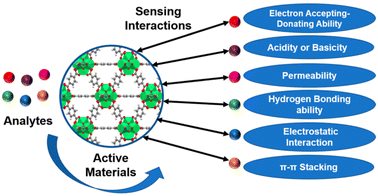 | ||
| Fig. 12 The schematic diagram for the various interactions involved during the sensing of analytes (reproduced with permission from ref. 83. Copyright 2021 Chemosensors). | ||
MOF nanostructures hold remarkable properties such as large surface area, tunable size having porous and active sites, and high chemical and thermal stability. Their most common applications are in adsorption, storage, catalysis, and sensing. Their features make them capable of the selective trapping and detection of various analytes from aqueous samples. Further advancements are achieved by modifications through the formation of nanocomposites of composites and their performance in electrochemical and luminescent-based detection performances.84 MOF nanostructures have vast sensing abilities including the detection of luminescent sensors, electrochemical sensors, gas sensors, and colorimetric sensors. Gumilar et al. outlined a basic method for creating hierarchical three-dimensional M-BDC (M = Cu, Mn, Ni, and Zr) MOFs that are constructed from two-dimensional nanosheets or nanoplates in the presence of acetonitrile and PVP as shape-directing substances.85 The production of the hierarchical sheet- or plate-like M-BDC MOFs is highly influenced by the mass ratio of the precursor metal to PVP and the quantity of acetonitrile (Fig. 13). While PVP aids in the nucleation and development of the MOF crystals. Acetonitrile maintains the solvation of the metal precursor. Bulk MOF crystals are produced when acetonitrile or PVP is removed. Only the hierarchical sheet-like electrode of Ni-BDC exhibits a significant amperometric response for glucose when used for nonenzymatic electrochemical glucose sensing. It has a high sensitivity of 635.9 μA mM−1 cm−2 and a broad linear range between 0.01 and 0.8 mM. The hierarchical sheet-like Ni-BDC electrode's detection limit for glucose is approximately 6.68 μM. This work is anticipated to offer practical methods for the future synthesis of hierarchical 3D MOFs and to encourage the direct application of MOFs in additional electrochemical applications.
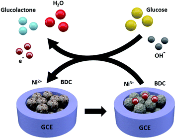 | ||
| Fig. 13 Electrochemical glucose sensing mechanism for the Ni-BDC sensor (reproduced with permission from ref. 85. Copyright 2020 RSC). | ||
The number of sensors based on MNPs/MOFs composites has dramatically expanded during the past years. The use of MNPs/MOFs composites in various sensing applications and how they work in concert to enhance the sensing display are briefly discussed. Then, they are classified into several sensors involving electrochemical sensing, fluorescence sensing, colorimetric sensing, SERS sensing, and CL/ECL sensing, which are introduced with special emphasis, in accordance with the types of sensors based on MNPs/MOFs composites.86 The traits of MNPs and MOFs in particular, which have synergistic processes and are frequently used to categorize the reciprocal effects of MNPs and MOFs, are reviewed as follows. (1) MNPs perform the role of active centers, whereas MOFs stabilize MNPs. (2) To ensure signal confidence, MOFs restrict easily aggregable MNPs. (3) Because MOFs have significant porosity, it is feasible to guarantee the admission of reactants of the right size, which then react with the MNPs as active centers. (4) Active sites for simultaneous catalysis can be either MNPs or MOFs. These sensors can further selectively detect inorganic metal ions, heavy metal ions, volatile organic compounds (VOCs), and persistent organic pollutants (POPs) from the environment to decontaminate and provide favorable surroundings for global existence.
The outstanding structural flexibility and selective host–guest response fabrication of MOFs-based chemical sensors have captivated researchers for the removal of VOCs. In MEMS-based sensors, after the nanoparticulation of MOFs, there occurs a simple and effective deposition of MOF NPs as the receptor layer. Moreover, the mechanical stability of multiple coatings of MOF NPs is enhanced after the size reduction of MOFs to MOF NPs due to multiple MOF NPs coatings.89
The fabrication of a capacitive sensor for VOCs based on the nanoparticles of MOF (Cu-BTC) was done by Homayoonnia et al. Various concentrations of methanol, isopropanol, ethanol, and acetone were detected by the capacitive sensor having films of MOF NPs, i.e., Cu-BTC NPs as the dielectric layer. Gas molecules, upon adsorbing into the pores of Cu-BTC NPs, produced a change in the capacitance value. The capacitance change after the interaction of analytes is attributed to a change in the dielectric constant of the material, i.e., Cu-BTC NPs [eqn (1)].
| C = (ε0εrA)/D | (1) |
Then, measurements were taken for the change in capacitance. The sensor proved high selectivity to polar analytes with a sensitivity value of 250–1500 ppm. In addition, the sensor possessed good response time and excellent linearity.87 Yeung et al. evidenced new advancements in the family of microelectromechanical sensors, i.e., MEMS by devising novel MOF-MSS sensors based on the ZIF-based family of MOFs. A suspension of four different MOF NPs derived from ZIF-7, ZIF-8, ZIF-65, and ZIF-71 was deposited on the MSS membrane via spray coating. The efficacy of these sensors can be understood by their unparalleled response time, i.e., 1–30 s and sub-ppm sensitivity range for the clear differentiation and selective determination of VOCs. A wide range of vapors from 26 VOCs containing various classes such as water, alcohol, ketone, carboxylic acid, amide, and ester was used for the study.89 Cao et al. further described the mechanistic path for the sensing of acetone using ZnFe2O4/Fe–ZnO nanocomposite with a response of 30.8–100 ppm, as shown in Fig. 14.90
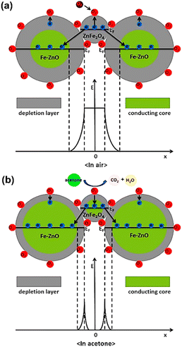 | ||
| Fig. 14 Schematic diagram of the structure and band for the ZnFe2O4/Fe–ZnO nanocomposite-based sensor (a) in air and (b) in acetone (reproduced with permission from ref. 90. Copyright 2020 Elsevier). | ||
Li et al. discussed some of the most recent developments in MOF sensing and switching materials with a focus on electrical, magnetic, ferroelectric, and chromoelectric sensing mechanisms.91 It was done with a thorough examination of the MOF–analyte interactions in these procedures, which are crucial to the sensing effectiveness of MOF-based sensors and switches.92,93 The authors have described in great detail the potential uses of MOF-based sensing and switching materials for the detection of water vapor, oxygen, toxic industrial gases (such as ammonia, hydrogen sulphide, nitrous oxide, sulphur dioxide, carbon oxides, and carbon disulfide), and VOCs (such as aliphatic and aromatic hydrocarbons, ketones, aldehydes, alcohols, chlorinated hydrocarbons, and N,N-dimethylformamide).94
Zirconium-based MOF nanostructures provide vast applications in the field of pesticide detection. Yang et al. employed a nanocomposite Fe3O4@SiO2@UiO-67 based on Zr-MOF for the selective detection of glyphosate. The prepared nanocomposite displays a selective feature due to its Zr–OH group that has a high affinity to the phosphate groups. In addition, an alteration in the fluorescence intensity of the nanocomposite occurs after interaction with the pesticide glyphosate. Silica incorporation retards electron transfer between the magnetic core of Fe3O4 and UiO-67, hence making the identification of glyphosate possible along with its concentration. The sensor was found to have very high sensitivity (detection limit = 0.093 mg L−1), high absorptivity (256.54 mg g−1), and excellent reusability.96
Similarly, the work of Li Ma et al. on the nanocomposite formed with the anchoring of Pt NPs over UiO66-NH2 provided acetylcholinesterase (AChE) biosensors for malathion, as depicted in Fig. 15. Due to the increased surface area and electron conductive channels, there was an enhancement in AChE immobilization. The sensor was found to have a good detection limit for malathion. Moreover, Pt@UiO-66-NH2@GCE was employed to successfully detect malathion in apple and cabbage samples.97
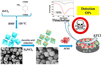 | ||
| Fig. 15 Schematic representation of detection of organophosphates using Pt@UiO-66-NH2@GCE (reproduced with permission from Li Ma et al.97 Copyright 2019 Elsevier). | ||
Li et al. have marked a milestone in this field by devising an immobilization-free and degradable sensor based on zeolitic imidazole framework-8 (ZIF-8) as a degradable carrier for methylene blue (MB) dye. The principle behind this sensor was the AChE-catalyzed hydrolytic reaction that occurred after the dissolution of ZIF-8/MB nanoparticles under acidic conditions. The release of many MB molecules takes place to generate a strong diffusion current. Hence, AChE inhibitors were monitored by a decline in the electrochemical signals. The sensor based on the nanostructure of ZIF-8 displayed good analytical performance for paraoxon with a detection limit of 1.7 ng mL−1.98
To put a check over environmental decontamination, Niazipour et al. put forward a 3D MOF (MOF-199) to detect antibiotics including azithromycin, amoxicillin, cefixime, ciprofloxacin, and gentamicin. The limit of detection was in the range from 0.14 to 0.62 μg L−1 in environmental and urine samples. Highly porous Cu nanofoam fibers were used to synthesize MOF-199 nanostructures for the solid-phase microextraction of antibiotics.99
In the literature, several applications of MOF-based materials have been shown for the sensing of nitroaromatics and pesticide as well.100,101 MOFs made from metals such as zirconium, cerium, and hafnium, which are in group IV of the periodic table, have drawn great attention because they operate in watery media and have noteworthy chemical stability in water. Since 2013, numerous research publications on related MOFs for chemosensors have been released.82 The functionality of chemoresistive sensors will also be improved by the addition of MOFs to a composite of active sensing materials. To prepare various electrically conductive MOFs and materials made from MOFs for use in a variety of applications, including chemoresistive sensors, numerous research activities have been carried out.102 For instance, UiO-66 and its derivatives can be used to prepare chemically resistive sensors for the detection of CO2, NO2, and SO2 gases.
Various optical, biological, and electrochemical sensors have been developed for the successful detection of heavy metal ions. For the facile detection of such heavy metal ions, nanostructures of MOFs can provide a milestone as they are easy to incorporate and provide more surface area, more binding abilities, and easily approachable charge transfer processes.
Subsequently, due to certain excellent characteristics, MOF nanocomposites help in boosting the sensing mechanism. The porous structure accompanying the luminescent and magnetic properties of MOFs makes them a suitable material for adsorption and hence a selective sensing material.
Luminescence-based detection of Hg2+ ions was done by Xu et al. using an aluminium-based MOF (MOF-253) nanoparticle composite. Loading of MOF-253 was done with luminescent ion Eu3+ and optically active carbon dots (CD), resulting in the formation of the sensor Eu3+/CD@MOF-253. The detection was based on the quenching ability of Hg2+ ions for the blue CD-based fluorescence without altering Eu3+-produced red luminescence. The method displayed excellent sensitivity with an LOD value of 13 ppb.11 Similarly, Liu et al. detected Cu2+ ions using four different MOF nanocages-based luminescent Ln-MOFs, 1-Ln (Ln = Eu, Tb, Gd, Dy). 1-Eu was found to have the highest selectivity and sensitivity for Cu2+ ions due to weak interactions between Cu2+ and the pyridyl sites. The synthesized compound also captured CO2 gas selectively.104
An electrochemical sensor that selectively and sensitively enhanced the detection of multiple heavy metals (Cu2+, Cd2+, Pb2+, Hg2+) was reported by Wang et al. The sulfur-containing nanocapsule-based MOF sensor [Co-TMC4R-BDC] has a bowl-shaped cavity comprised of every nanocapsule unit (TMC4R = tetra(4-mercaptopyridine)calix[4]resorcinarene). The edges of the octahedron were occupied by eight equally distributed sulfur atoms, which efficiently trapped heavy metal ions. The reason for trapping was the stronger binding efficiency between sulfur and ions along with the existence of cation–π bonding between the phenyl ring and heavy metal ions. Further, a glass carbon electrode was employed to form Co-TMC4R-BDC/GCE for the simultaneous and individual detection for all four ions, which showed high sensitivity and low LOD value.105 A core/shell UiO-66-NH2@PANI composite was successfully prepared using a straightforward hydrothermal method with PANI coatings.106 The generated composite modified electrode was used for the detection of trace quantities of cadmium ions using differential pulse stripping voltammetry. The analysis of cadmium ions in actual samples served as a demonstration of the practical applicability. A consistently nanosized octahedron, MOF-199, was prepared, and it demonstrated outstanding Cr(VI)-triggered oxidoreductase catalytic capabilities.107 Cr(VI) was present, and the chemosensor used this to activate the catalytic activity of MOF-199, which is similar to an oxidoreductase. TMB was used as the chromogenic substrate. The mechanistic pathway for the sensing is shown in Fig. 16. The nanozyme's steady-state kinetics was studied for the activity of the imitating enzyme. The concept of nanoscale MOF-based artificial catalysts with enzyme-mimicking activity can also be expanded in the future to monitor and detect other important compounds.
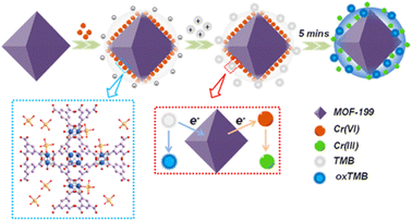 | ||
| Fig. 16 Schematic representation for the Cr(VI) sensing using nanozyme MOF-199 (reproduced with permission from ref. 107. Copyright 2021 ACS). | ||
Wang et al. devised a highly sensitive colorimetric sensor (AuNP@MOF) comprising Au NP anchored in iron-porphyrin base MOF Fe-TCPP-MOF for the selective detection of Hg2+ ions. Hg2+ ion triggered the catalysis process to reduce methylene blue (MB) dye and thereby was sensed. Upon the introduction of the sensor into the sample, the Hg2+ ion was linked with the AuNPs surface and forms a gold amalgam. The gold amalgam formed to act as a catalyst for MB reduction. The sensor showed high sensitivity with an LOD of 103 pM and a response time of 2 s.108 The work by Bhattacharjee et al. offers fresh perspectives on constructing selective and sensitive MOF-based sensors for nitroaromatics, such as explosive detection. A novel mixed-ligand Ni-MOF performing “turn-off” detection of trinitrophenol (TNP) from a purely aqueous medium was devised.109 The synthesized MOF has good sensitivity (LOD = 87 ppb) and significant quenching efficacy by the combinatorial effects of RET, ICT, PET, and interactions as well as competitive absorption processes. In addition, the MOF-based chemosensor's quick reaction (5 s), recyclable nature, and accurate recovery of TNP in environmental water samples indicate its dependability and applicability.
3.3 Adsorption
The phenomenon of a solid substance's surface absorbing molecules or ions from the surrounding gas or liquid is known as adsorption. It has been extensively utilized in environmental fields such as heavy metal ion adsorption, PPCPs, and wastewater treatment due to its simple operation and low cost.110,111 Traditional adsorbents (such as zeolite and silica) are currently experiencing difficulties such as a steady rate of rate and little capacity for adsorption.112,113 One of the best adsorbents for water are COFs and POPs because of their extremely high Hg(II) adsorption capacity, quick adsorption kinetics, and high recycling efficiency. Hg(II) adsorptive removal using the nanoscale porosity of organic polymers (mesoporous POPs, microporous POPs, COFs) has been reported.114 DMTZ-PMO (a mesoporous silica-based porous material) containing thiol and thiadiazole moieties have also been used for the adsorption-based removal of toxic Hg(II) ions.115 The mesoporous walls' covalently-bonded organic activity serves as a Hg(II) scavenger, and the material's stiff structure offers it stability to work well as an adsorbent throughout a wide range of pH, solvent, and temperature. The material is an effective adsorbent for Hg(II) removal because soft centers, such as sulphur, increase the mercury ion adsorption through soft–soft interactions. Despite their impressive benefits, porous organic nanoparticles are typically functionalized with phosphorus and sulphur-containing groups for effective interaction with mercury, which is dangerous to the environment. Therefore, for environmental concerns, mercury uptake with these nanoporous polymers is unacceptable. In the same context, owing to their ample pore sizes and highly determined surface area, carbon-derived MOFs have emerged as competitive adsorbents.116Chemical oxidation, membrane technology, adsorption, and coagulation–flocculation are some of the technologies that have emerged for controlling wastewater pollution. Numerous efforts have been made to get rid of pollutants in the environment from water.117,118 Due to the comprehensive consideration of cost reduction, procedure simplification, removal efficiency, and operational feasibility, the method of adsorption is a preferred option. As a novel type of adsorbent, nanomaterials derived from MOF are dominant in this process. In addition, scalable fabrication allows production at the industrial level more options.
Noticeably, knowing the mechanism of adsorption is important for more than just knowing the basics of adsorption; it is also important for improving the adsorption technology and developing it further for commercialization. The adsorbents' porosity and surface area typically have an impact on the adsorption capacity through van der Waals interaction. The syntheses conditions have an impact on the structural properties of MOFs that are produced through organic ligands and the coordination of metal ions. The synthesis of MOFs is generally influenced by several parameters, including the ligand, solvent, additive, duration, functional group, and metal source. Porosity, crystal size, morphology, MOF yield, and crystallinity are all affected by these parameters.
The analytical performance of toxic metals with MOFs in food and water samples will be evaluated. There are various metal ions, e.g., Cd2+, Pb2+, Hg2+, Zn2+, and Cr3+, reported as analytes for this process, but herein, we have explained the examples of lead and mercury.
The Cu-based MOF with an –SH group for rice and tea matrices has the best adsorption capacity and preconcentration factor ((SHeFe3O4/Cu3(BTC)2) and (CS/Cu3(BTC)2–SH)), respectively, of the MOF types used for analysis and remove lead from food matrices.132,133 MIL-101(Cr)/Fe3O4@PTSC (Cr-based), which uses fish as a matrix, outperforms other copper-based MOFs in terms of performance. For lead analysis with high recovery in sediment matrices, Fe3O4–DHz/Cu3(BTC)2 and Fe3O4 pyridine/Cu3(BTC)2 MOFs are structures with excellent analytical performance.134 These studies demonstrate that the effect of the matrix and the performance of the MOF structures that are functionalized with a variety of matrix with various properties and may be acceptable for analysis should be taken into consideration when selecting MOFs. In studies using MOFs for lead analysis in environmental and food samples, Cu-based MOFs have high absorption capacity, while Zr-based MOFs, due to their stable nature in water environments, perform better in aqueous matrices. In aqueous matrices, Zr-based MOFs are preferred more because of their stability in aqueous environments.
Zr-based MOFs are typically used in studies related to matrices of water, whereas Cu-based MOFs are usually adopted for the investigation of Hg using MOFs in foods. In the research conducted by Wu et al., the modification method of photosynthesis was utilized to boost the MOFs' adsorption capacity for heavy metal ions and the tea matrix.135,136 The wastewater matrix had a greater adsorption capacity in the study than wastewater and tea matrices, but the tea matrix's adsorption capacity increased with increasing adsorption time. It has been resolved that the effect of matrix and adsorption time is significant in matrices such as the matrix of tea. Aqueous matrices highlight the significance of selecting the appropriate metal ion in MOF synthesis, where the analytes are not just ligands or functional groups.
In conclusion, in food Pb analysis, Cu-based MOFs are typically used, even though lead ions from water samples are typically removed by Zr-based MOFs. In Pb analysis, the utilization of MOFs based on copper and zirconium has numerous advantages. The functionalization of MOFs to improve their adsorption efficiency plays a significant role in the trace analysis of heavy metal ions because it tends to enlarge the capacity. Adsorbents known as MOFs have advantages in terms of sorption capacity and prefactor.
With the right source of metal ions and functionalization for the analysis of toxic metal and ligand, MOFs are appropriate for use in environmental and food samples as highly sensitive, preconcentrating, and selective adsorbents having good capacity of adsorption. As a result, MOFs are favorable adsorbents for the quick and effective extraction of metal ions (heavy) from complex samples for environmental pollution control and food safety.
Porous carbons made from the pyrolysis of a subtype of MOFs were used to clean PPCP-polluted water, which is activated by KOH, by metal azolate framework-6 (MAF-6). A record of commonly used PPCPs includes acidic ibuprofen, weakly-acidic TCS, diclofenac sodium, basic atenolol, and oxybenzone; the MAF-6-derived porous carbons could potentially adsorb them. Importantly, after solvent washing, the carbon acquired 1000 °C promoted recyclability and had exceptional adsorptive properties for ibuprofen and diclofenac.140
Due to their widespread use as antipyretics and analgesics, KTP and NAP are considered EP's [KTP = ketoprofen[2-(3-benzoylphenyl) propanoic acid]; NAP = naproxen[2-(6-methoxynaphthalen-2-yl) propanoic acid]]. Both drugs can be assimilated into the water system in a variety of ways.4 MIL-101(Cr) and GnO [graphene oxide] were used to prepare highly effective and porous MOF composites for the removal of KTP and NAP from water media. MIL-101/GnO composites outperformed pristine MIL-101 when it came to the adsorption of the tested anti-inflammatory drugs (AIDs). When compared to pure MIL-101 and mercantile-activated carbon, GnO/MIL-101 (3.0%) exhibited a greater adsorption capacity for NAP of 1.4 and 2.1 times, respectively. In addition, the as-prepared composite was reconstructed without significant deterioration and could be used for numerous cycles of continuous adsorption. It is found that pharmaceutically active and complex anti-inflammatory nonsteroidal micropollutants adsorb well on wastewater, surface, and ground samples.
Lin et al. developed MOF-808, MOF-802, and UiO-66 Zr(IV)-based MOFs. These MOFs were found to have remarkable adsorption capacities, as shown in Fig. 17. Amodiaquine, a chloroquine analogue, is widely used to treat and prevent malaria and other conditions of arthritis. Consequently, it is frequently found in wastewater and drinking water.141 Tella et al. made zinc-carboxylate MOFs that were used to break down amodiaquine in water media.142 [Zn2(fum)2(bpy)] and [Zn4O(bdc)3] MOFs had adsorption capacities of 0.478 and 47.62 mg g−1, respectively, for amodiaquine at an ideal pH = 4.3, according to the experimental profile. Five PPCPs were removed from the pristine and hydroxyl group of functionalized MIL-101s.137 PPCPs include ketoprofen, BPA, TCS, NPX (anti-inflammatory and nonsteroidal drugs), and PCMX (p-chloro-m-xylenol), a bactericidal used in baby powders, deodorants, and creams because more hydrogen acceptor and donors are present.143,144
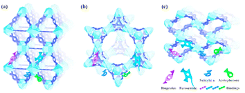 | ||
| Fig. 17 Schematic diagrams of the interaction of ibuprofen, furosemide, salicylic acid, and acetophenone with UiO-66 (a), MOF-808 (b), and MOF-802 (c) (reproduced with permission from ref. 141. Copyright 2018 ACS). | ||
Due to their ease of fabrication, modification, ecosustainability, and convenient recovery, magnetic nanomaterials have attracted great attention these days. They also have important characteristics such as dispersibility, large surface area, and small size,137 which allow these magnetic nanoparticles to be modified to achieve adsorption specificity and selectivity toward the target compounds.
Due to the increased specific surface area and optimal porous structure, the pyrolysis of MOFs with additional carbon sources has the potential to significantly improve their adsorption capacity. For illustration, Xu et al. carbonized ZIF-8 (carbon-Z), ZIF/sucrose (carbon-ZS), and ZIF/dicyandiamide (carbon-ZD) and synthesized three MOF-derived N-doped porous carbons.147
Due to their limitations, such as low activity after reuse and inevitable aggregation, MOFs produced relatively fewer examples of pure metal compounds as adsorbents than carbons. P-Al2O3 MSs (an innovative penetrable Al2O3 microsphere) were used to immobilize radionuclides (Eu(III) and U(VI)) from wastewater and performed much better than c-Al2O3 (commercial) nanomaterials in this process, showing energetic and excessive adsorption.148 The uptake process can be explained by a variety of adsorption mechanisms, including hydrophobic, electrostatic, acid–base, p–p interaction, and H-bonding.146,150 H-bond interaction is proposed as the primary cause of the extensive adsorption. Derivatives with distinctive structures require special attention. In addition, according to studies, the adsorptive efficiency of adsorbents was primarily dependent on the N and/or O species doping, i.e., heteroatom doping and the properties of the surface (e.g., porosity, pure volume, and BET area), which may be controlled by adding an external template or activating agent.151,152 However, a more in-depth research is required to comprehend the adsorption mechanism because the effect of heteroatoms was not clearly demonstrated. A pore volume and larger surface area can make material transfer easier and make the active adsorption sites more visible, thus increasing the capture capacity.
The adsorption capacity is significantly influenced by the pore size and, in part, the species of the pollutants being absorbed. Micropores, for instance, are advantageous for MB adsorption and mesopores for TC capture.153 However, the method for controlling the pore size remains a mystery. Specifically, the monopolized porous structure of the micropore has the inherent disadvantage of limited diffusion.154 In short, using MOFs as precursors to create nanomaterials with remarkable functionalities could be an efficient way to boost their adsorption competitiveness in both industrial settings and academics, as shown in Table 1.
| Sr. no. | MOF nano structures | Target pollutant | Mode of decontamination | Reference |
|---|---|---|---|---|
| 1 | Fe–Cx | Organic pollutant (4-nitrophenol) | Fenton-like catalytic degradation (catalyst amount = 0.08 g L−1) (removal efficiency = 89% wt) | 158 |
| 2 | CoP/Fe2P@mC | Dye (Rh B) | Photocatalytic degradation (catalyst = 100 mg L−1) (removal efficiency = 94%) | 70 |
| 3 | CoN/N–C@SiO2 | Antibiotic (tetracycline) | PMS-activated catalytic degradation (removal efficiency = 98.7%) | 159 |
| 4 | α-Fe2O3/ZIF-67 | Antibiotic (ciprofloxacin) | PMS-activated catalytic degradation (catalyst amount = 0.1 g L−1) (removal efficiency = 99%) | 160 |
| 5 | Pt@M–Cr2O3 | VOC (toluene) | Catalytic degradation (surface area = 77.4 m2 g−1) | 161 |
| 6 | NiZn-MOF NSs | Organic pollutant (tyrosinase) | Sensing (LOD = 6.5 nM) | 162 |
| 7 | Co3O4-350 | VOC (formaldehyde) | Sensing (LOD = 10 ppm) | 163 |
| 8 | (EuOF/quantum dots) | Trinitrotoluene (TNT) | Sensing (LOD = 3 ppb) | 164 |
| 9 | Co3O4@MOF-74 | Fenamiphos insecticide | Sensing (LOD = 3 pM) | 165 |
| 10 | ZJU/GCE | Heavy metal ions (Cd2+ and Pb2+) | Sensing (LOD = 1.10 nM for Pb2+) | 166 |
| 11 | TiO2@Fe-imidazole | Chlorpyrifos pesticide | Sensing (LOD = 2–10 ng mL−1) | 167 |
| 12 | ZnFe2O4/Fe–ZnO | VOC (acetone) | Sensing (response = 30.8–100 ppm) | 90 |
| 13 | CuO/Cu-MOF | Nitric oxide (NO) | Sensing (LOD = 7.8 nM) | 168 |
| 14 | Gr/MOF-GCE | Heavy metal ion sensing (As3+) | Sensing (LOD = 0.06 ppb) | 169 |
| 19 | Dy-MOF | Heavy metal ions (Pb2+ and Cu2+) | Langmuir adsorption (LOD = 0.4 μg L−1 [Pb2+] and 0.264 μg L−1 [Cu2+]) | 170 |
| 16 | (MOF-NC) | Cu ions | Adsorption (qe = 33.44 mg g−1) | 171 |
| 17 | (CDM6-K1000) | Antibiotics (ibuprofen, diclofenac) | Adsorption (ibuprofen = 408 mg g−1) (diclofenac = 503 mg g−1) isotherm = Langmuir | 63 |
| 18 | (Carbon–Fe/Fe3C910) | Antibiotic (tetracycline) | Adsorption (511.06 mg g−1) isotherm = Langmuir | 172 |
| 19 | ZIF-8@AG-CA | Organic contaminants | Adsorption (pore volume = 0.58 cm3 g−1) | 154 |
| 20 | Zn0.05TiOxNy@MOF-5 | Heavy metal ion (Zn2+) | Adsorption and sensing (LOD = 0.0014 mg L−1) isotherm = Langmuir and Freundlich | 173 |
MOFs stand out in the field of drugs because of their remarkable adsorption properties. The MOF adsorption properties empower them to specifically adsorb and deliver drugs, prompting further developed drug viability and diminished secondary effects the productive expulsion of different drugs from the oceanic framework has been a considerable test due to the discrete physico-substance properties and less concentration.155,156 Adsorption is one of the reassuring technologies for the effective removal of various pharmaceuticals from the water system because of its high elimination ability, fewer operation prices, and depletion in the emission of secondary dangerous pollutants.157
4. Conclusion & future perspective
In a nutshell, a critical appraisal of advancements in the field of nanotechnology associated with MOF as an environmental treatment has been undertaken herein. Owing to their tunable structure, enhanced surface area, and accessible electron-transfer processes, MOF nanostructures are envisaged as a boon for ecosystem management. Restricting the size of MOFs in the nanoregime whether through the formation of nanocomposites or nanoparticles brings vast applicability to the versatility of MOFs. Herein, this review comprises various methods for the synthesis of MOF nanostructures along with their application as competent remedial agents for the removal of effluents from the environment.The present review emphasized the synthetic modes of MOF nanocomposites or nanoparticles along with their applications as nanocatalysts, nanosensors, and nanoadsorbents. Several sensitive and selective applications involving the enhanced attributes of MOF nanostructures were classified and reviewed here.
Despite several advancements in the field of environmental detoxification using MOF nanostructures, there is some lag in their applicability. The prospects in this research area will be approached by following some localized purposes described here, which should be covered at the earliest.
(a) Surfactant molecules are generally employed for the stabilization and effective growth of MOF/MNPs composites, which can block the adsorption sites of MNPs by adsorbing on their surface. This adsorptive action could diminish the sensing attribute of such nanocomposites. Hence, more efficient strategies should be employed for the incorporation of MNPs on MOFs with controlled size and shape without using these surfactants.
(b) In MOF nanocomposites, using nanoscale MOF as a host is tedious and challenging. Generally, there is the employment of nanoparticles in the host MOFs rather than using MOF nanoparticles themselves for synthesizing nanocomposites. Removing this difficulty may put a milestone in the usability of MOF nanostructures.
(c) There should be certain advancements in long-term self-stability, e.g., photostability, thermal, and moisture stability of such MOF nanostructures, to improve their functionalization.
(d) To expand this field and enhance ecological balance, certain technologies should be linked with these nanostructures. Combination with paper chips and test strips can make MOF nanostructures suitable sensors for heavy metal ions and can be used in portable devices.
(e) Correlating MOF nanostructures with optical, plasmonic, and electronic fields can improve their catalytic and sensing performance using electrochemical principles.
(f) In most research works, self-prepared laboratory samples are used; therefore, real environmental samples should be tested to exactly determine the usefulness of the developed methods at the ground level.
(g) The quantum yield obtained for the nanostructures should be improved by synthetic modifications. Yield should be enough to use these in industrial applications for the large-scale decontamination of aqueous and air contaminants.
Last but not least, despite having some challenges pending resolution, MOF nanostructures have a brilliant future ahead. This area with minor advancements can further open up an avenue for the maintenance of a healthy environment and ecological stability. The restorative approach that it carries for the decontamination of environmental toxicity is the root cause for the extension of this work for the betterment of our flourishing environment.
Author contributions
Indu Sharma – writing, drafting and data collection; Jaspreet Kaur – drafting and analysing; Gargi Poonia – data collection and writing; Surinder Kumar Mehta – analysing and proof-reading; Ramesh Kataria – conceptualisation, analysing and proof-reading.Conflicts of interest
There are no conflicts to declare.Acknowledgements
The authors acknowledge the assistance of Panjab University and IIIT Una throughout all the aspects of this comprehensive study and analysis. Indu Sharma is also grateful to the Council of Scientific and Industrial Research (CSIR, grant number: 09/0135(12681)/2021-EMR-I) for the financial assistance.References
- J. Darabdhara and M. Ahmaruzzaman, Chemosphere, 2022, 304, 135261 CrossRef CAS PubMed
.
- S. Mosleh, M. R. Rahimi, M. Ghaedi, K. Dashtian and S. Hajati, RSC Adv, 2016, 6, 63667–63680 RSC
.
- A. J. Ebele, M. Abou-Elwafa Abdallah and S. Harrad, Emerg. Contam., 2017, 3, 1–16 CrossRef
.
- M. Oves, M. Z. Khan and I. M. I. Ismail, Mod. Age Environ. Probl. their Remediat., 2017, 1–237 Search PubMed
.
- I. B. Gomes, L. C. Simões and M. Simões, Sci. Total Environ., 2018, 643, 1348–1356 CrossRef CAS PubMed
.
- N. S. Thomaidis, A. G. Asimakopoulos and A. A. Bletsou, Glob. Nest J., 2012, 14, 72–79 Search PubMed
.
- T. Rasheed, M. Bilal, F. Nabeel, M. Adeel and H. M. N. Iqbal, Environ. Int., 2019, 122, 52–66 CrossRef CAS PubMed
.
- J. L. Wilkinson, P. S. Hooda, J. Barker, S. Barton and J. Swinden, Crit. Rev. Environ. Sci. Technol., 2016, 46, 336–381 CrossRef CAS
.
- M. Safaei, M. M. Foroughi, N. Ebrahimpoor, S. Jahani, A. Omidi and M. Khatami, TrAC - Trends Anal. Chem., 2019, 118, 401–425 CrossRef CAS
.
- S. Kader, M. O. Raimi, V. Spalevic, I. Asomeji and W. B. Raheem, Manuscr. Draft, 2023, 2301011, 1–10 Search PubMed
.
- P. Kumar, A. Deep and K. H. Kim, TrAC - Trends Anal. Chem., 2015, 73, 39–53 CrossRef CAS
.
- L. Qiu, C. Yu, X. Wang, Y. Xie, A. M. Kirillov, W. Huang, J. Li, P. Gao, T. Wu, X. Gu, Q. Nie and D. Wu, Inorg. Chem., 2019, 58, 4524–4533 CrossRef CAS PubMed
.
- Y. Wang, C. Pan, W. Chu, A. K. Vipin and L. Sun, Nanomaterials, 2019, 9, 439 CrossRef CAS PubMed
.
- S. Subudhi, S. P. Tripathy and K. Parida, Inorg. Chem. Front., 2021, 8, 1619–1636 RSC
.
- A. Malik, M. Nath, S. Mohiyuddin and G. Packirisamy, ACS Omega, 2018, 3, 8288–8308 CrossRef CAS PubMed
.
- R. Dolas, C. Saravanan and B. P. Kaur, Ultrason. Sonochem., 2019, 58, 104609 CrossRef CAS PubMed
.
- O. Azizabadi, F. Akbarzadeh, S. Danshina, N. P. S. Chauhan and G. Sargazi, J. Solid State Chem., 2021, 294, 121897 CrossRef CAS
.
- F. Israr, D. K. Kim, Y. Kim, S. J. Oh, K. C. Ng and W. Chun, Ultrason. Sonochem., 2016, 29, 186–193 CrossRef CAS PubMed
.
- S. Li, L. Tan and X. Meng, Adv. Funct. Mater., 2020, 30, 1–26 Search PubMed
.
- T. Chalati, P. Horcajada, R. Gref, P. Couvreur and C. Serre, J. Mater. Chem., 2011, 21, 2220–2227 RSC
.
- G. Sargazi, D. Afzali and A. Mostafavi, J. Porous Mater., 2018, 25, 1723–1741 CrossRef CAS
.
- M. V. Varsha and G. Nageswaran, J. Electrochem. Soc., 2020, 167, 155527 CrossRef CAS
.
- O. J. De Lima Neto, A. C. d. O. Frós, B. S. Barros, A. F. De Farias Monteiro and J. Kulesza, New J. Chem., 2019, 43, 5518–5524 RSC
.
- F. Zhang, T. Zhang, X. Zou, X. Liang, G. Zhu and F. Qu, Solid State Ionics, 2017, 301, 125–132 CrossRef CAS
.
- H. M. Yang, X. Liu, X. L. Song, T. L. Yang, Z. H. Liang and C. M. Fan, Trans. Nonferrous Met. Soc. China, 2015, 25, 3987–3994 CrossRef CAS
.
- J. Z. Wei, F. X. Gong, X. J. Sun, Y. Li, T. Zhang, X. J. Zhao and F. M. Zhang, Inorg. Chem., 2019, 58, 6742–6747 CrossRef CAS PubMed
.
- A. Pandey, N. Dhas, P. Deshmukh, C. Caro, P. Patil, M. Luisa García-Martín, B. Padya, A. Nikam, T. Mehta and S. Mutalik, Coord. Chem. Rev., 2020, 409, 213212 CrossRef CAS
.
- J. Z. Wei, X. L. Wang, X. J. Sun, Y. Hou, X. Zhang, D. D. Yang, H. Dong and F. M. Zhang, Inorg. Chem., 2018, 57, 3818–3824 CrossRef CAS PubMed
.
- E. M. C. Morales, M. A. Méndez-Rojas, L. M. Torres-Martínez, L. F. Garay-Rodríguez, I. López, I. E. Uflyand and B. I. Kharisov, Polyhedron, 2021, 210, 1–7 CrossRef
.
- A. Schaate, P. Roy, A. Godt, J. Lippke, F. Waltz, M. Wiebcke and P. Behrens, Chem.–Eur. J., 2011, 17, 6643–6651 CrossRef CAS PubMed
.
- S. A. A. Razavi, M. Y. Masoomi and A. Morsali, Ultrason. Sonochem., 2017, 37, 502–508 CrossRef CAS PubMed
.
- L. G. Qiu, Z. Q. Li, Y. Wu, W. Wang, T. Xu and X. Jiang, Chem. Commun., 2008, 31, 3642–3644 RSC
.
- M. Y. Masoomi, A. Morsali and P. C. Junk, RSC Adv, 2014, 4, 47894–47898 RSC
.
- Z. Luo, S. Fan, C. Gu, W. Liu, J. Chen, B. Li and J. Liu, Curr Med Chem, 2019, 3341–3369 CrossRef CAS PubMed
.
- N. Stock and S. Biswas, Chem. Rev., 2012, 112, 933–969 CrossRef CAS PubMed
.
- K. M. Ø. Jensen, C. Tyrsted, M. Bremholm and B. B. Iversen, ChemSusChem, 2014, 7, 1–19 CrossRef PubMed
.
- Y. Huo, S. Xiu, L. Meng and B. Quan, Chem. Eng. J., 2023, 451, 138572 CrossRef CAS
.
- R.L. Barns, E.D. Kolb, R.A. Laudise, E.E. Simpson and K.M. Kroupa, J.Cryst. Growth, 1976, 34, 189–197 CrossRef CAS
.
- M. Miyamoto, S. Kohmura, H. Iwatsuka, Y. Oumi and S. Uemiya, CrystEngComm, 2015, 17, 3422–3425 RSC
.
- B. A. Rabenau, Angew. Chem., 1985, 24, 1026–1040 CrossRef
.
- J. Mira, J. Solid State Chem., 2009, 182, 2685–2690 CrossRef
.
- T. He, D. Chen, X. Jiao, Y. Xu and Y. Gu, Langmuir, 2004, 20, 8404–8408 CrossRef CAS PubMed
.
- S. Assemblies, Angew Chem, 2003, 43, 2872–2875 Search PubMed
.
- Y. Xu, M. Xie, X. Li, F. Shao, S. Li, S. Li, Y. Xu, J. Chen, F. Zeng and Y. Jiao, J. Colloid Interface Sci., 2022, 626, 426–434 CrossRef CAS PubMed
.
- S. Aslam, J. Zeng, F. Subhan, M. Li, F. Lyu, Y. Li and Z. Yan, J. Colloid Interface Sci., 2017, 505, 186–195 CrossRef CAS PubMed
.
- S. Zheng, Q. Li, H. Xue, H. Pang and Q. Xu, Natl. Sci. Rev., 2020, 7, 305–314 CrossRef CAS PubMed
.
- V. J. Ariyamparambil and B. Kandasubramanian, Chem. Eng. J. Adv., 2022, 11, 100355 CrossRef CAS
.
- M. A. Al-Baadani, L. Xu, K. Hii Ru Yie, A. Sun, X. Gao, K. Cai, B. A. Al-Shaaobi, A. M. Al-Bishari, L. Cai, X. Shen, J. Liu and P. Ma, Mater. Des., 2022, 217, 110596 CrossRef CAS
.
- H. R. Moon, D. W. Lim and M. P. Suh, Chem. Soc. Rev., 2013, 42, 1807–1824 RSC
.
- A. Aijaz and Q. Xu, J. Phys. Chem. Lett., 2014, 5, 1400–1411 CrossRef CAS PubMed
.
- H. Wang, J. Zhao, C. Liu, Y. Tong and W. He, ACS Omega, 2021, 6, 4807–4815 CrossRef CAS PubMed
.
- S. Guo, L. Chi, T. Zhao, Y. Nan, X. Sun, Y. Huang, B. Hou and X. Wang, J. Electroanal. Chem., 2021, 880, 114915 CrossRef CAS
.
- J. H. Zhao, Y. Wang, X. Tang, Y. H. Li, F. T. Liu, Y. Zhang and K. Li, Dalt. Trans., 2019, 48, 3560–3565 RSC
.
- K. Kumagai, T. Uematsu, T. Torimoto and S. Kuwabata, Chem. Mater., 2021, 33, 1607–1617 CrossRef CAS
.
- T. Noor, N. Zaman, H. Nasir, N. Iqbal and Z. Hussain, Electrochim. Acta, 2019, 307, 1–12 CrossRef CAS
.
- E. Akbarzadeh, H. Z. Soheili, M. Hosseinifard and M. R. Gholami, Mater. Res. Bull., 2020, 121, 110621 CrossRef CAS
.
- W. Xia, J. Zhu, W. Guo, L. An, D. Xia and R. Zou, J. Mater. Chem. A, 2014, 2, 11606–11613 RSC
.
- Z. Xiang, Y. Song, J. Xiong, Z. Pan, X. Wang, L. Liu, R. Liu, H. Yang and W. Lu, Carbon, 2019, 142, 20–31 CrossRef CAS
.
- S. Wang, Y. Hou, S. Lin and X. Wang, Nanoscale, 2014, 6, 9930–9934 RSC
.
- J. Qin, J. Wang, J. Yang, Y. Hu, M. Fu and D. Ye, Appl. Catal. B Environ., 2020, 267, 118667 CrossRef CAS
.
- S. Ye, M. Yan, X. Tan, J. Liang, G. Zeng, H. Wu, B. Song, C. Zhou, Y. Yang and H. Wang, Appl. Catal. B Environ., 2019, 250, 78–88 CrossRef CAS
.
- H. Yi, M. Yan, D. Huang, G. Zeng, C. Lai, M. Li, X. Huo, L. Qin, S. Liu, X. Liu, B. Li, H. Wang, M. Shen, Y. Fu and X. Guo, Appl. Catal. B Environ., 2019, 250, 52–62 CrossRef CAS
.
- I. I. Alkhatib, C. Garlisi, M. Pagliaro, K. Al-Ali and G. Palmisano, Catal. Today, 2020, 340, 209–224 CrossRef CAS
.
- H. Robatjazi, D. Weinberg, D. F. Swearer, C. Jacobson, M. Zhang, S. Tian, L. Zhou, P. Nordlander and N. J. Halas, Sci. Adv., 2019, 5, 1–11 Search PubMed
.
- J. Becerra, D. T. Nguyen, V. N. Gopalakrishnan and T. O. Do, ACS Appl. Energy Mater., 2020, 3, 7659–7665 CrossRef CAS
.
- F. Guo, Y. P. Wei, S. Q. Wang, X. Y. Zhang, F. M. Wang and W. Y. Sun, J. Mater. Chem. A, 2019, 7, 26490–26495 RSC
.
- Y. Huang, Y. Zhang, X. Chen, D. Wu, Z. Yi and R. Cao, Chem. Commun., 2014, 50, 10115–10117 RSC
.
- C. Venkata, K. Raghava, V. V. N. Harish, J. Shim, M. V Shankar, N. P. Shetti and T. M. Aminabhavi, Int. J. Hydrogen Energy, 2019, 45, 7656–7679 Search PubMed
.
- R. Liang, F. Jing, L. Shen, N. Qin and L. Wu, Nano Res, 2015, 8, 3237–3249 CrossRef CAS
.
- B. Hu, J. Y. Yuan, J. Y. Tian, M. Wang, X. Wang, L. He, Z. Zhang, Z. W. Wang and C. Sen Liu, J. Colloid Interface Sci., 2018, 531, 148–159 CrossRef CAS PubMed
.
- Y. Lei, C. S. Chen, Y. J. Tu, Y. H. Huang and H. Zhang, Environ. Sci. Technol., 2015, 49, 6838–6845 CrossRef CAS PubMed
.
- Z. Ye, J. A. Padilla, E. Xuriguera, E. Brillas and I. Sirés, Appl. Catal. B Environ., 2020, 266, 118604 CrossRef CAS
.
- Y. Yao, H. Chen, C. Lian, F. Wei, D. Zhang, G. Wu, B. Chen and S. Wang, J. Hazard. Mater., 2016, 314, 129–139 CrossRef CAS PubMed
.
- J. Tang and J. Wang, Chem. Eng. J., 2019, 375, 122007 CrossRef CAS
.
- C. Wang, H. Wang, R. Luo, C. Liu, J. Li, X. Sun, J. Shen, W. Han and L. Wang, Chem. Eng. J., 2017, 330, 262–271 CrossRef CAS
.
- Y. Du and X. Han, J. Mater. Chem. A, 2018, 3 Search PubMed
.
- G. Yilmaz, C. F. Tan, M. Hong and G. W. Ho, Adv. Funct. Mater., 2017, 1704177, 1–9 Search PubMed
.
- W. Oh, Z. Dong and T. Lim, Applied Catal. B Environ., 2016, 194, 169–201 CrossRef CAS
.
- L. Chen, X. Zuo, S. Yang, T. Cai and D. Ding, Chem. Eng. J., 2019, 359, 373–384 CrossRef CAS
.
- P. Ji, J. B. Solomon, Z. Lin, A. M. Wilders, R. F. Jordan and W. Lin, J. Am. Chem. Soc., 2017, 139, 11325–11328 CrossRef CAS PubMed
.
- H. Li, B. Xu, J. He, X. Liu, W. Gao and Y. Mu, Chem. Commun., 2015, 51, 16703–16706 RSC
.
- S. Pal, S. S. Yu and C. W. Kung, Chemosensors, 2021, 9, 306 CrossRef CAS
.
- L. E. Kreno, K. Leong, O. K. Farha, M. Allendorf, R. P. Van Duyne and J. T. Hupp, Chem. Rev., 2012, 112, 1105–1125 CrossRef CAS PubMed
.
- X. Fang, B. Zong and S. Mao, Nano-Micro Lett., 2018, 10, 1–19 CrossRef PubMed
.
- G. Gumilar, Y. V. Kaneti, J. Henzie, S. Chatterjee, J. Na, B. Yuliarto, N. Nugraha, A. Patah, A. Bhaumik and Y. Yamauchi, Chem. Sci., 2020, 11, 3644–3655 RSC
.
- J. Xu, J. Ma, Y. Peng, S. Cao, S. Zhang and H. Pang, Chinese Chem. Lett., 2023, 34, 107527 CrossRef CAS
.
- S. Homayoonnia and S. Zeinali, Sensors Actuators, B Chem., 2016, 237, 776–786 CrossRef CAS
.
- P. Mochalski, J. King, M. Klieber, K. Unterkofler, H. Hinterhuber, M. Baumann and A. Amann, Analyst, 2013, 138, 2134–2145 RSC
.
- H. H. Yeung, G. Yoshikawa, K. Minami and K. Shiba, J. Mater. Chem. A, 2020, 8, 18007–18014 RSC
.
- E. Cao, Z. Guo, G. Song, Y. Zhang, W. Hao and L. Sun, Sensors Actuators B. Chem., 2020, 325, 128783 CrossRef CAS
.
- C. Zhang, L. Sun, Y. Yan, Y. Liu, Z. Liang, Y. Liu and J. Li, J. Mater. Chem. C, 2017, 5, 2084–2089 RSC
.
- W. Shi, F. Xing, Y. L. Bai, M. Hu, Y. Zhao, M. X. Li and S. Zhu, ACS Appl. Mater. Interfaces, 2015, 7, 14493–14500 CrossRef CAS PubMed
.
- L. F. Wang, W. M. Zhuang, G. Z. Huang, Y. C. Chen, J. Z. Qiu, Z. P. Ni and M. L. Tong, Chem. Sci., 2019, 10, 7496–7502 RSC
.
- H. Y. Li, S. N. Zhao, S. Q. Zang and J. Li, Chem. Soc. Rev., 2020, 49, 6364–6401 RSC
.
- H. Sohrabi, P. Salahshour Sani, Y. Orooji, M. R. Majidi, Y. Yoon and A. Khataee, Food Chem. Toxicol., 2022, 165, 113176 CrossRef CAS PubMed
.
- Q. Yang, J. Wang, X. Chen, W. Yang, H. Pei, N. Hu, Z. Li, Y. Suo, T. Li and J. Wang, J. Mater. Chem. A, 2018, 6, 2184–2192 RSC
.
- L. Ma, Y. He, Y. Wang, Y. Wang, R. Li, Z. Huang, Y. Jiang and J. Gao, Electrochim. Acta, 2019, 318, 525–533 CrossRef CAS
.
- X. Li, X. Gao, P. Gai, X. Liu and F. Li, Sensors Actuators, B Chem., 2020, 323, 128701 CrossRef CAS
.
- S. Niazipour, J. B. Raoof and M. Ghani, J. Chromatogr. A, 2021, 1660, 462677 CrossRef CAS PubMed
.
- M. Wagner, K. Y. Andrew Lin, W. Da Oh and G. Lisak, J. Hazard. Mater., 2021, 413, 1–8 CrossRef PubMed
.
- M. Wagner, K. Y. Andrew Lin, W. Da Oh and G. Lisak, J. Hazard. Mater., 2021, 413, 125325 CrossRef CAS PubMed
.
- W.-T. Koo, J.-S. Jang and I.-D. Kim, Chem, 2019, 5, 1938–1963 CAS
.
- P. Kumar, K. H. Kim, V. Bansal, T. Lazarides and N. Kumar, J. Ind. Eng. Chem., 2017, 54, 30–43 CrossRef CAS
.
- B. Liu, W. P. Wu, L. Hou and Y. Y. Wang, Chem. Commun., 2014, 50, 8731–8734 RSC
.
- F. F. Wang, C. Liu, J. Yang, H. L. Xu, W. Y. Pei and J. F. Ma, Chem. Eng. J., 2022, 438, 135639 CrossRef CAS
.
- Y. Wang, L. Wang, W. Huang, T. Zhang, X. Hu, J. A. Perman and S. Ma, J. Mater. Chem. A, 2017, 5, 8385–8393 RSC
.
- W. Shi, M. He, W. Li, X. Wei, B. Bui, M. Chen and W. Chen, ACS Appl. Nano Mater., 2021, 4, 802–810 CrossRef CAS
.
- X. Wang, H. Wang, L. Guo, G. Chen, R. Kong, F. Qu and L. Xia, Analyst, 2020, 145, 1362–1367 RSC
.
- S. Bhattacharjee, S. Bera, R. Das, D. Chakraborty, A. Basu, P. Banerjee, S. Ghosh and A. Bhaumik, ACS Appl. Mater. Interfaces, 2022, 14, 20907–20918 CrossRef CAS PubMed
.
- S. Tian, C. Zhang, D. Huang, R. Wang, G. Zeng, M. Yan, W. Xiong, C. Zhou, M. Cheng, W. Xue and Y. Yang, Chem. Eng. J., 2020, 389, 123423 CrossRef CAS
.
- H. Li, Y. Li, B. Li, D. Liu and Y. Zhou, Chemosphere, 2012, 89, 1307–1315 CrossRef PubMed
.
- M. Barczak, R. Dobrowolski, P. Borowski and D. A. Giannakoudakis, Microporous Mesoporous Mater, 2020, 299, 110132 CrossRef CAS
.
- S. Huang, W. Deng, L. Zhang, D. Yang and Q. Gao, Microporous Mesoporous Mater, 2020, 302, 110204 CrossRef CAS
.
- A. Modak, P. Bhanja, M. Selvaraj and A. Bhaumik, Environ. Sci. Nano, 2020, 7, 2887–2923 RSC
.
- S. Das, S. Chatterjee, S. Mondal, A. Modak, B. K. Chandra, S. Das, G. D. Nessim, A. Majee and A. Bhaumik, Chem. Commun., 2020, 56, 3963–3966 RSC
.
- J. He, Y. Xu, W. Wang, B. Hu, Z. Wang, X. Yang, Y. Wang and L. Yang, Arab. J. Chem., 2022, 15, 103955 CrossRef
.
- Z. Luo, Y. He, D. Zhi, L. Luo, Y. Sun, E. Khan, L. Wang, Y. Peng, Y. Zhou and D. C. W. Tsang, Sci. Total Environ., 2019, 696, 133990 CrossRef CAS
.
- Y. Zhou, Y. He, Y. Xiang, S. Meng, X. Liu, J. Yu, J. Yang, J. Zhang, P. Qin and L. Luo, Sci. Total Environ., 2019, 646, 29–36 CrossRef CAS PubMed
.
- L. Huang, R. Shen and Q. Shuai, J. Environ. Manage., 2021, 277, 111389 CrossRef CAS PubMed
.
- L. Li, X. L. Liu, H. Y. Geng, B. Hu, G. W. Song and Z. S. Xu, J. Mater. Chem. A, 2013, 1, 10292–10299 RSC
.
- W. Zhang, Y. Hu, J. Ge, H. L. Jiang and S. H. Yu, J. Am. Chem. Soc., 2014, 136, 16978–16981 CrossRef CAS PubMed
.
- Z. Hasan and S. H. Jhung, J. Hazard. Mater., 2015, 283, 329–339 CrossRef CAS PubMed
.
- B. Van De Voorde, B. Bueken, J. Denayer and D. De Vos, Chem. Soc. Rev., 2014, 43, 5766–5788 RSC
.
- H. Furukawa, K. E. Cordova, M. O'Keeffe and O. M. Yaghi, Science, 2013, 341, 1230444 CrossRef PubMed
.
- Z. Zhao, X. Li, S. Huang, Q. Xia and Z. Li, Ind. Eng. Chem. Res., 2011, 50, 2254–2261 CrossRef CAS
.
- M. P. Suh, H. J. Park, T. K. Prasad and D. W. Lim, Chem. Rev., 2012, 112, 782–835 CrossRef CAS PubMed
.
- K. Lu, T. Aung, N. Guo, R. Weichselbaum and W. Lin, Adv. Mater., 2018, 30, 1–20 Search PubMed
.
- Y. N. Wu, M. Zhou, B. Zhang, B. Wu, J. Li, J. Qiao, X. Guan and F. Li, Nanoscale, 2014, 6, 1105–1112 RSC
.
- H. Saleem, U. Rafique and R. P. Davies, Microporous Mesoporous Mater, 2016, 221, 238–244 CrossRef CAS
.
- B. Li, H. M. Wen, Y. Cui, W. Zhou, G. Qian and B. Chen, Adv. Mater., 2016, 28, 8819–8860 CrossRef CAS PubMed
.
- B. Szczęśniak, J. Choma and M. Jaroniec, J. Colloid Interface Sci., 2018, 514, 801–813 CrossRef PubMed
.
- S. Cai, W. Li, P. Xu, X. Xia, H. Yu, S. Zhang and X. Li, Analyst, 2019, 144, 3729–3735 RSC
.
- M. Manoochehri and M. Mehraban, RSC, 2018, 42, 17636–17643 Search PubMed
.
- M. R. Sohrabi and Z. Matbouie, Microchemica Acta, 2013, 180, 589–597 CrossRef CAS
.
- Y. Wu, G. Xu, W. Liu, J. Yang, F. Wei, L. Li and W. Zhang, Microporous Mesoporous Mater, 2015, 210, 110–115 CrossRef CAS
.
- F. Ke, J. Jiang, Y. Li, J. Liang, X. Wan and S. Ko, Appl. Surf. Sci., 2017, 413, 266–274 CrossRef CAS
.
- T. Rasheed, M. Bilal, A. Ahmad, F. Nabeel, R. Naresh, L. Fernando, R. Ferreira, H. Nguyen and H. M. N. Iqbal, Environ. Res., 2020, 185, 109436 CrossRef CAS PubMed
.
- P. Zhao, N. Liu, C. Jin, H. Chen, Z. Zhang, L. Zhao, P. Cheng and Y. Chen, Inorg. Chem., 2019, 58, 8787–8792 CrossRef CAS PubMed
.
- S. Lin, Y. Zhao and Y. S. Yun, ACS Appl. Mater. Interfaces, 2018, 10, 28076–28085 CrossRef CAS PubMed
.
- I. Ahmed, B. N. Bhadra, H. J. Lee and S. H. Jhung, Catal. Today, 2018, 301, 90–97 CrossRef CAS
.
- S. Lin, Y. Zhao and Y. Yun, ACS Appld Mater Interfaces, 2018, 10, 28076–28085 CrossRef CAS PubMed
.
- A. C. Tella, S. O. Owalude, S. J. Olatunji, V. O. Adimula, S. E. Elaigwu, L. O. Alimi, P. A. Ajibade and O. S. Oluwafemi, J. Environ. Sci., 2017, 64, 264–275 CrossRef PubMed
.
- T. Xuan, V. Hung, S. Thanh and H. Choi, J. Hazard. Mater., 2013, 254–255, 345–353 Search PubMed
.
- P. Taylor, S. Saha, U. Sarkar and S. Mondal, Phys Rev Lett, 2018, 125, 151802 Search PubMed
.
- B. N. Bhadra and S. H. Jhung, Microporous Mesoporous Mater, 2018, 270, 102–108 CrossRef CAS
.
- B. N. Bhadra, J. K. Lee, C. Cho and S. H. Jhung, J.Chem. Eng., 2018, 343, 225–234 CrossRef CAS
.
- S. Xu, Y. Lv, X. Zeng and D. Cao, Chem. Eng. J., 2017, 323, 502–511 CrossRef CAS
.
- S. Huang, H. Pang, L. Li, S. Jiang, T. Wen, L. Zhuang and B. Hu, Chem. Eng. J., 2018, 353, 157–166 CrossRef CAS
.
- I. Ahmed, T. Panja, N. A. Khan, M. Sarker, J. Yu, S. H. Jhung and J. Yu, ACS Appl. Mater. Interfaces, 2017, 9, 10276–10285 CrossRef CAS PubMed
.
- H. J. An, B. N. Bhadra, N. A. Khan and S. H. Jhung, Chem. Eng. J., 2018, 343, 447–454 CrossRef CAS
.
- B. N. Bhadra and S. H. Jhung, J. Hazard. Mater., 2017, 340, 179–188 CrossRef CAS PubMed
.
- B. N. Bhadra, I. Ahmed, S. Kim and S. H. Jhung, Chem. Eng. J., 2017, 314, 50–58 CrossRef CAS
.
- E. Article, Q. Wen, J. Di, Y. Zhao, Y. Wang and J. Yu, Chem. Sci., 2013, 4, 4378–4382 RSC
.
- C. Wang, J. Kim, J. Tang, J. Na, Y. M. Kang, M. Kim, H. Lim, Y. Bando, J. Li and Y. Yamauchi, Angew. Chemie - Int. Ed., 2020, 59, 2066–2070 CrossRef CAS PubMed
.
- K. G. Pavithra, P. Senthil Kumar, P. Sundar Rajan, A. Saravanan and M. Naushad, Korean J. Chem. Eng., 2017, 34, 2787–2805 CrossRef CAS
.
- M. B. Cristóvão, R. Janssens, A. Yadav, S. Pandey, P. Luis, B. Van der Bruggen, K. K. Dubey, M. K. Mandal, J. G. Crespo and V. J. Pereira, J. Hazard. Mater., 2020, 392, 122330 CrossRef PubMed
.
- Y. Xu, T. Liu, Y. Zhang, F. Ge, R. M. Steel and L. Sun, J. Mater. Chem. A, 2017, 5, 12001–12014 RSC
.
- D. Chen, S. Chen, Y. Jiang, S. Xie, H. Quan, L. Hua, X. Luo and L. Guo, RSC Adv, 2017, 7, 49024–49030 RSC
.
- S. Zhang, H. Gao, X. Xu, R. Cao, H. Yang, X. Xu and J. Li, Chem. Eng. J., 2020, 381, 122670 CrossRef CAS
.
- B. Hashemzadeh, H. Alamgholiloo, N. Noroozi Pesyan, E. Asgari, A. Sheikhmohammadi, J. Yeganeh and H. Hashemzadeh, Chemosphere, 2021, 281, 130970 CrossRef CAS PubMed
.
- X. Chen, X. Chen, S. Cai, J. Chen, W. Xu, H. Jia and J. Chen, Chem. Eng. J., 2018, 334, 768–779 CrossRef CAS
.
- Y. Wen, R. Li, J. Liu, X. Zhang, P. Wang, X. Zhang, B. Zhou, H. Li, J. Wang, Z. Li and B. Sun, Anal. Chim. Acta, 2020, 1127, 131–139 CrossRef CAS PubMed
.
- W. Zhou, Y. P. Wu, J. Zhao, W. W. Dong, X. Q. Qiao, D. F. Hou, X. Bu and D. S. Li, Inorg. Chem., 2017, 56, 14111–14117 CrossRef CAS PubMed
.
- R. Kaur, A. K. Paul and A. Deep, Forensic Sci. Int., 2014, 242, 88–93 CrossRef CAS PubMed
.
- H. Karimi-Maleh, M. L. Yola, N. Atar, Y. Orooji, F. Karimi, P. Senthil Kumar, J. Rouhi and M. Baghayeri, J. Colloid Interface Sci., 2021, 592, 174–185 CrossRef CAS PubMed
.
- W. Ye, Y. Li, J. Wang, B. Li, Y. Cui, Y. Yang and G. Qian, J. Solid State Chem., 2020, 281, 121032 CrossRef CAS
.
- P. Arulpriya, T. Krishnaveni, T. Shanmugasundaram and K. Kadirvelu, J. Ind. Eng. Chem., 2022, 112, 146–161 CrossRef CAS
.
- N. Alizadeh, A. Salimi and T. K. Sham, Microchim. Acta, 2021, 188, 1–11 CrossRef PubMed
.
- M. Baghayeri, M. Ghanei-Motlagh, R. Tayebee, M. Fayazi and F. Narenji, Anal. Chim. Acta, 2020, 1099, 60–67 CrossRef CAS PubMed
.
- A. Jamali, A. A. Tehrani, F. Shemirani and A. Morsali, Dalt. Trans., 2016, 45, 9193–9200 RSC
.
- N. Bakhtiari, S. Azizian, S. M. Alshehri, N. L. Torad, V. Malgras and Y. Yamauchi, Microporous Mesoporous Mater, 2015, 217, 173–177 CrossRef CAS
.
- W. Xiong, Z. Zeng, G. Zeng, Z. Yang, R. Xiao, X. Li, J. Cao, C. Zhou, H. Chen, M. Jia, Y. Yang, W. Wang and X. Tang, Chem. Eng. J., 2019, 374, 91–99 CrossRef CAS
.
- S. A. Younis, T. A. Ali and P. Serp, J. Environ. Chem. Eng., 2021, 9, 106186 CrossRef CAS
.
Footnote |
| † Equal contribution of authors. |
| This journal is © The Royal Society of Chemistry 2023 |

