Recent advances in the shaping of metal–organic frameworks
Xiao-Min
Liu
a,
Lin-Hua
Xie
 *b and
Yufeng
Wu
*a
aInstitute of Circular Economy, Beijing University of Technology, Beijing 100124, P. R. China. E-mail: wuyufeng3r@126.com
bBeijing Key Laboratory for Green Catalysis and Separation and Department of Chemistry and Chemical Engineering, College of Environmental and Energy Engineering, Beijing University of Technology, Beijing 100124, P. R. China. E-mail: xielinhua@bjut.edu.cn
First published on 8th June 2020
Abstract
The shaping of metal–organic frameworks (MOFs), referring to the integration of small submillimeter MOF crystals into bulk samples with desired size, shape and mechanical stability, is an important step for the practical use of this class of porous materials in many applications. MOFs are constructed by the coordination bonding of metal ions/clusters and organic ligands. Since coordination bonds are mostly weaker than covalent bands, MOFs show a relatively low stability compared to conventional porous materials, such as zeolites or porous carbon-based materials. Thus, many shaping methods for the conventional porous materials involving treatments under harsh conditions could not be directly applied to prepare shaped MOFs. However, the inorganic–organic hybrid nature of MOFs also affords the opportunity of developing unique methods for shaping the materials. Herein, an overview of some classic methods for the shaping of MOFs is presented, including granulation, extrusion, spray drying, and pressing. In addition, the recently developed methods for the preparation of shaped MOFs used in separation and gas storage, including templated shaping, self-shaping, shaping by in situ growth on substrates, and shaping with sacrificial materials, are highlighted.
1. Introduction
Over the last two decades, metal–organic frameworks (MOFs)1–6 have been demonstrated to show great potential in gas adsorption,7–11 separation,12–17 catalysis,18–22 sensing23–27 and many other applications due to their structural variety, modifiable pore surface, controllable pore size, high specific surface area, and so on.28–36 The syntheses of new MOF structures have been extensively studied in the past decades.37–42 In the last few years, increasing attention has been paid to the utilization of MOF materials in practical use.43–48 Though some commercial products based on MOF materials have been launched recently,49 there are still some challenging issues to be addressed for the application of MOFs in real devices, including the shaping of MOFs. Generally, the as-synthesized MOF samples are obtained as small crystals less than tens to hundreds of microns, and a bulk sample of MOF crystals is commonly in a powder form. However, the specific size, shape, hardness, mechanical strength and/or microscopic morphology of the materials are/is required in practical applications, because there are some disadvantages for powdery materials, such as difficulty in handling, easy to spill, poor mass/heat transfer rate, high pressure drop when being piled up, unsatisfactory mechanical stability, and low volumetric efficiency in a container.50,51 Therefore, it is of great significance to develop methods for the preparation of shaped MOF products with better mechanical durability than the original powdery samples without apparently sacrificing their intrinsic properties. As a class of promising materials in many applications, the shaping of MOFs would be an important step for future industrialization of MOF materials.Many preparation methods for the shaped bulks or composites of MOF crystals have been reported, and the representative ones include granulation,52–54 extrusion,55–57 spray drying,58–60 pressing,61–63 sol–gel method64–66 and layer-by-layer deposition.67–69 In fact, many shaping methods for MOFs are derived from the shaping of some conventional porous materials, such as zeolites, porous carbon-based materials, which are commonly found as granules, extrudates, spheres, beads, honeycombs, foams, monoliths, and so on.51,70 However, it should be noted that the shaping of MOFs cannot completely follow that of the other materials. In fact, even the shaping procedures for zeolites and porous carbon-based materials are very different. The shaping of porous carbon-based materials, such as activated carbons, carbon nanotubes and templated carbons, is generally achieved by the high-temperature carbonization of the polymer precursors in the molds.71 Unlike porous carbon-based materials, which are amorphous structures, zeolites are usually submicron crystallites, and typically shaped by making a mixture of zeolite crystallites and an inorganic or organic binder (including silica, metal oxides, tetramethylorthosilicate and methylsiloxane) with a desired shape followed by calcination at high temperatures.72 The high temperatures for shaping of zeolites or porous carbon-based materials are generally higher than 800 °C. These conditions are harsh for MOFs because the MOF structures are constructed by coordination bonding between metal ions/clusters and organic ligands, which normally starts to decompose at the temperature range of 300–500 °C.73 The low stability (thermal, chemical, and mechanical stability) of MOFs has long been regarded a drawback for this class of porous materials.74,75 This characteristic also brings many difficulties to the shaping processes of MOFs. However, there are still many encouraging works reported on this topic. Particularly, in the past few years, some new shaping methods for MOFs have emerged, including templated shaping,76–78 self-shaping,79 shaping by in situ growth on substrates,80 and shaping with sacrificial materials,81,82 besides the conventional mechanical shaping methods. With the help of these methods, the powdery MOF samples can be transformed into some special solid materials with certain geometric shapes or sizes (Fig. 1).83 Herein, an overview of the various existing methods for the shaping of MOFs is presented, and the recently developed methods for the preparation of shaped MOFs used in separation and gas storage are highlighted.
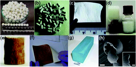 | ||
| Fig. 1 Examples showing different shapes of MOFs: (a) granule, (b) pellet, (c) thin film, (d) gel, (e) foam, (f) paper sheet, (g) monolith and (h) hollow structure (scale bar 500 nm (inset 200 nm)). Reprinted with permission from ref. 83. Copyright 2018 Elsevier. | ||
2. The shaping of MOFs
The research works on the shaping of MOF materials have attracted increasing attention in the past few years. Many MOFs, including ZIF-8 (also called MAF-4),84,85 MOF-5,86,87 MIL-101,88 MOF-177,89 UiO-66,90 MIL-53,91–93 HKUST-1,94etc., have been studied for making shaped products. The shaped MOF products of some well-known MOFs, such as HKUST-1, ZIF-8, MOF-5, MIL-101 and MOF-177, have been already commercialized by chemical companies worldwide, such as BASF, Decco, and NuMat Technologies.43 The shaping processes of these MOFs are very different. Bazer-Bachi et al. proposed that the optimum method for the shaping of a MOF material is highly dependent on the application, because the shape of the product plays an important role in the practical application process.95 In addition, operating conditions in the practical application, such as temperature, pressure and solvent medium, which may generate stress on the MOF material, need to be carefully pre-considered for the shaping process. Previously, Stylianou et al. made a detailed summary on some shaped products of MOF materials, such as granules, flakes, films, foams, gels, paper sheets, hollow structures, etc.83 A review of shaped MOFs by mechanical methods was reported by Lee et al., such as granulation, extrusion, spray drying, pressing, etc.96 Shah et al. discussed the mechanical properties of some reported macroscopic shaped MOF structures, including granules, pellets, tablets, monoliths, and gels.97 After those works, some new and appealing methods for the shaping of MOFs appeared. Herein, an overview of the recent advances and some typical methods in the shaping of MOFs is presented. From a different perspective compared with those in the literature, the methods for the shaping of MOFs are categorized into five classes in this work, namely, mechanical shaping, templated shaping, self-shaping, shaping by in situ growth on substrates, and shaping with sacrificial materials. Specific subclasses of these methods have also been given. As an extension of the design and synthesis, the shaping technology of MOF materials would also be of great significance to the future practical application of this class of porous materials. It should be mentioned that when this review was under review a perspective about MOF gels and monoliths and a review paper about monolithic MOFs were reported.98,992.1. Mechanical shaping
Mechanical shaping is a method of integrating powdery materials into bulky materials with a certain shape and size by means of external tools. This class of shaping methods can be further divided into several subclasses, including granulation, extrusion, spray drying and pressing. The processes of mechanical-shaping are relatively simple and fast, however, the resulting materials often show a loss of structural integrity and a compromise in porosity.Two aspects should be considered for the auxiliary additives in the wet granulation technology. On the one hand, dispersion media and binders generally act as auxiliary additives to promote granulation in this technology, whereas the negative influence of these additives on the active sites and Lewis acid sites of MOF materials needs to be avoided. Eddaoudi and co-workers investigated the effect of rubbery and glassy polymeric binders on the CO2 adsorption performance of the shaped MOFs.101 It was found that the CO2 adsorption capacity of NbOFFIVE-1-Ni was substantially retained after it was fabricated into beads with 10% glassy polymer, poly(methyl methacrylate) or polysulfone, while an obvious reduction of CO2 adsorption capacity was observed when the rubbery polymer polyethylene glycol was used as a binder. Lee et al. obtained the shaped products of several MOFs (including MIL-100(Fe), MIL-101(Cr), UiO-66(Zr), and UiO-66(Zr)-NH2) by using mesoporous alumina as a binder and water as the solvent.54 The results of gas adsorption and penetration experiments showed that the binder had little effect on the exposed chemically active sites and Lewis acid sites on the pore surface of the shaped MOFs. The MOF powder sample, adhesive amorphous mesoporous alumina, and dispersion medium (water) were uniformly mixed. The mixture was rolled up to form spherical bodies using a roller machine (Fig. 2). In another example, it has also been demonstrated that the use of adhesive additives had little effect on the physical and chemical properties of the granulated MOF spheres.102 A silica sol as a binder was applied to prepare the shaped spheres with sizes of 1.18–1.70 mm from a MIL-100(Fe) powder sample using a mixing granulator. The adsorption capacity of granulated MIL-100(Fe) decreased only in proportion to the binder content compared to that of the original material, indicating that there was no intrusion of adhesives into the pores of MOFs.
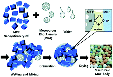 | ||
| Fig. 2 The preparation of MOF granules/spheres through agglomeration of MOF and amorphous mesoporous alumina particles by a wet granulation technology. Reprinted with permission from ref. 54 published by the Royal Society of Chemistry. | ||
On the other hand, the auxiliary additives benefit the mechanical strength and wear resistance of the granulated MOFs. It has been demonstrated that the addition of some auxiliary reagents, such as powdery sucrose, polyvinyl formal (PVFM), and calcium alginate, improves the mechanical strength and wear resistance of the shaped MOFs. Ren et al. successfully prepared the shaped Zr-MOF (UiO-66) spheres with good mechanical properties from a powder sample of Zr-MOF and a ground powder sample of sucrose by means of a centrifugal granulator (Fig. 3).53 The obtained powder mixture was placed into the centrifugal working chamber of the granulator to form a spherical pellet under a self-contained water-spraying centrifuge. The diameter of the pellet could be adjusted in the range of 0.5–15 mm by controlling the shaping duration. The results showed that the pellets prepared by using 10 wt% sucrose as a binder had a good mechanical strength and could resist the abrasion in a real environment of hydrogen storage. A special method for producing MOF beads with different sizes, ranging from 250 microns to a few millimeters, was reported by Cousin-Saint-Remi and co-workers.103 The authors prepared ZIF-8/PVFM microspheres by heating the mixture of ZIF-8 and PVFM with the help of a syringe granulator. The PVFM was first dissolved in dimethylformamide (DMF) by heating, and then a ZIF-8 powder was added into the hot polymer solution to produce a viscous slurry. Continuous stirring was afterwards applied to evaporate the solvent until the solution reached a certain viscosity to ensure the effective formation of beads. Finally, the MOF beads were produced by dropping the slurry into a liquid tank containing the deionized water. Once the droplets came into contact with water, the slurry was hardened into a small ball in an instant, and the small ball is generally in an irregular spherical shape. The ZIF-8/PVFM particles produced by this method showed a high mechanical strength, which is almost identical to that of the commercial zeolite materials. Recently, Lee et al. prepared UiO-66 beads by a calcium alginate method.104 The powder sample of UiO-66 was first mixed with sodium alginate in water to produce a slurry, which was then added to an aqueous solution of CaCl2·6H2O drop by drop using a pipette. Due to the water-insoluble nature of calcium alginate, the MOF slurry drops solidified in 30 minutes. The resultant UiO-66 beads showed crushing strength similar to alumina or silica with only a 10% reduction in the surface area. In fact, the calcium alginate method to produce MOF beads was first developed by Blom and co-workers.105 With a similar procedure, the authors also prepared the beads containing over 95 wt% CPO-27-Ni by solidifying the suspension of MOF particles in a chitosan solution with an alkali solution since chitosan is not soluble in alkali solution.
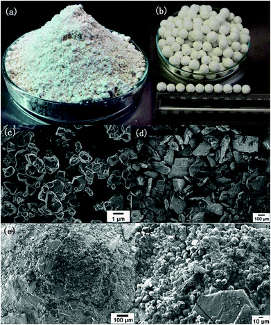 | ||
Fig. 3 (a) The optical images of a mixed powder sample of desolvated Zr-MOF (UiO-66) and sucrose (9![[thin space (1/6-em)]](https://www.rsc.org/images/entities/char_2009.gif) : :![[thin space (1/6-em)]](https://www.rsc.org/images/entities/char_2009.gif) 1 by weight); (b) optical image of shaped spherical pellets with a diameter around 8 mm; SEM images of the desolvated Zr-MOF (c), the ground sucrose powder (d), and the pellets (e and f). Reprinted with permission from ref. 53. Copyright 2015 Elsevier. 1 by weight); (b) optical image of shaped spherical pellets with a diameter around 8 mm; SEM images of the desolvated Zr-MOF (c), the ground sucrose powder (d), and the pellets (e and f). Reprinted with permission from ref. 53. Copyright 2015 Elsevier. | ||
In this technology, retaining the adsorption and recycling performances of the shaped MOF materials is a great challenge. The influence of the extrusion process on the adsorption and recycling performances is closely related to the developed extrusion technology. Khabzina et al. reported that the functionalized UiO-66 material (UiO-66-COOH) could be shaped and used in an ammonia purification filter.106 The MOF material was first mixed with water and a binder to obtain a paste containing 72.5 vol% UiO-66-COOH, 22 vol% water, and 5.5 vol% polysiloxane (silicone). Finally, a 1.5 mm long small cylinder of shaped product was obtained by the extrusion method. Various cross-sectional shapes could be obtained by controlling the shape of the flow outlet or mediating the shear mode (Fig. 4). The high-density samples of the shaped UiO-66-COOH obtained by this method could act as air purification adsorbents to effectively remove NH3, and the performance was superior to that of the commercially activated carbon. In addition to the conventional extrusion, there are some reported examples for the continuous production of shaped MOFs by extrusion. James et al.107 applied twin-screw and single-screw extruders for continuous production of various metal complexes and MOFs, including Ni(salen), Ni(NCS)2(PPh3)2, and HKUST-1, ZIF-8, and Al-fumarate. It was found that the specific surface area of Al-fumarate after extrusion was comparable to that of an Al-fumarate sample obtained by the conventional method. Janiak and co-workers recently reported the shaping of some hydrothermally stable MOFs, including Al-fumarate, MIL-160(Al) and MIL-101(Cr), with some hydrophilic polymer binders, including polyacrylic acid (PAA), sodium polyacrylate (PAANa), polyethylene glycol (PEG), polyethylene imine (PEI), polyvinyl alcohol (PVA) and polyvinyl pyrrolidone (PVP).108 The resultant monoliths were prepared by a freeze-casting method, where the mixture of MOF, polymer, and water was extruded out from a syringe after it was frozen in liquid nitrogen, and the final product was obtained by freeze drying of the extrudate. With such a shaping method, negligible pore blocking was achieved for 12 of the 21 investigated MOF@polymer composites. A simple and energy-efficient CH4 capture from low-concentration sources (such as landfill gas) by a shaped MOF product has been reported by Sadiq et al.109 The water-stable MOF, Al-fumarate, was selected to mix with high heating rate magnetic nanoparticles (MgFe2O4) and poly(vinyl alcohol) particles to prepare a pellet sample by extrusion. At 1 bar and 300 K, the shaped Al-fumarate showed a high CH4 adsorption capacity (18.2 cm3 g−1). Dynamic release experiments indicated that there was no substantial loss of CH4 adsorption capacity for the extruded pellet after more than 10 cycles of regeneration with a speed of 6 minutes per cycle. On the other hand, the authors pointed out that suitable particle size and density were prerequisites for the formation of shaped adsorbents, and smaller particles could cause excessive pressure drop or respiratory resistance, which is not desirable in practical applications.
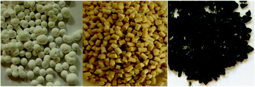 | ||
| Fig. 4 The photographs of UiO-66-COOH beads obtained by freeze granulation (left) and extrudates (center), and of commercial type K adsorbent (activated carbon) from 3 M (right). Reprinted with permission from ref. 106. Copyright 2018 American Chemical Society. | ||
In addition, the auxiliary additives used in the extrusion process have a great influence on the properties of shaped materials. Rationally controlling the components and the contents of additives benefits the surface area, crushing strength and density of the shaped MOFs. For example, the major components for a shaped MOF material are the MOF powder (UTSA-16), binder (PVA) and plasticizer (water or propanol), which were mixed to form the shaped sample by extrusion.110 Among them, the binder could integrate particles with a plasticizer which reduces the viscosity between particles. The most common plasticizer is water, and some other organic solvents with low boiling points or organic-water mixtures could also be used as plasticizers. The specific surface area for a shaped sample with a lower binder content (<2 wt%) was hardly reduced compared to that of the pristine MOF. In contrast, the specific surface area of a sample with a binder content of 3 wt% was reduced by 5%. Furthermore, the crushing strength and particle density of the extruded material increased steadily with the increase of binder content. The density of the extruded MOF containing only 2 wt% of binder was comparable to the extrudates of commercial zeolites. On increasing the content of the binder, the crushing strength was significantly increased and much higher than that of the commercial zeolite, however, at the expense of a reduction of surface area. Recently, Figueira et al. reported a facile method to shape powdery MOF samples into MOF pellets.111 A mixture of MOF particles and a small amount of water was straightforward extruded out from a syringe. The resulting pellets easily broke apart after dehydration or immersion in water. However, after the unstable MOF pellets were coated with poly(methyl methacrylate) (PMMA) by immersing the pellets in a PMMA solution in CH2Cl2, the authors claimed that the PMMA coated MOF pellets could preserve their integrity for months in ambient air and for one week in liquid water.
In the past few years, the fabrication of delicate MOF-based products with the aid of 3D-printing setups is gaining increasing attention.112–116 Essentially, the 3D printing of a MOF-based product is a shaping process of MOF particles by extrusion. Thakkar et al. first reported 3D-printed monoliths of two MOFs, MOF-74(Ni) and UTSA-16(Co).112 A homogeneous suspension of MOF powder together with bentonite clay (as a binder) was first prepared. The suspension was mixed with another solution containing PVA (as a plasticizer), water, and ethanol, producing an extrudable paste, which was then loaded into the syringe of a 3D printer. Monoliths with a 3D structure pre-designed by the AutoCAD software were finally printed in a layer-by-layer manner (Fig. 5). Some other binders and plasticizers were also used to prepare 3D-printed MOF monoliths. For example, Furukawa and co-workers recently reported the preparation of MOF monoliths of HKUST-1, CPL-1, ZIF-8, and UiO-66-NH2 with a modified 3D printer.116 The inks for 3D printing were prepared by mixing MOF nanocrystals, 2-hydroxyethyl cellulose (as a binder), PVA (as a plasticizer), and water with a weight composition of 0.25![[thin space (1/6-em)]](https://www.rsc.org/images/entities/char_2009.gif) :
:![[thin space (1/6-em)]](https://www.rsc.org/images/entities/char_2009.gif) 0.02
0.02![[thin space (1/6-em)]](https://www.rsc.org/images/entities/char_2009.gif) :
:![[thin space (1/6-em)]](https://www.rsc.org/images/entities/char_2009.gif) 0.01
0.01![[thin space (1/6-em)]](https://www.rsc.org/images/entities/char_2009.gif) :
:![[thin space (1/6-em)]](https://www.rsc.org/images/entities/char_2009.gif) 0.65. The authors emphasized that the optimization of the ink composition was highly important, and an ideal ink should be highly viscous, show proper flowability when an external force is applied, and hold its shape in a stationary state.
0.65. The authors emphasized that the optimization of the ink composition was highly important, and an ideal ink should be highly viscous, show proper flowability when an external force is applied, and hold its shape in a stationary state.
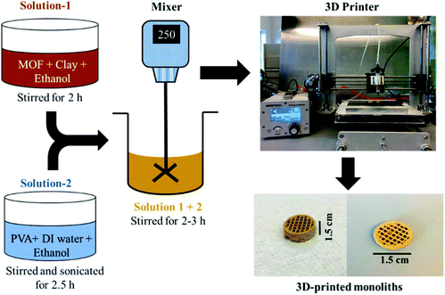 | ||
| Fig. 5 Schematic of the preparation procedure of a 3D-printed MOF monolith. Reprinted with permission from ref. 112. Copyright 2017 American Chemical Society. | ||
Spray drying can be used to construct MOF-based hollow superstructures, which have great potential in some fields, such as chemical sensing and selective reactors. It is quite different from the preparation of materials with superstructures by conventional methods, which commonly require the application of sacrificial polymer templates, chemical etching or interfacial manipulation. The preparation of hollow MOF superstructures and their adsorption properties have been studied by several research groups. Maspoch et al. used a two-fluid nozzle for the spray-drying synthesis of hollow HKUST-1 superstructures and nanoHKUST-1 crystals.117 A solution of Cu(NO3)2·2.5H2O and H3btc (H3btc = 1,3,5-benzenetricarboxylic acid) in a mixture of DMF, ethanol and water (1![[thin space (1/6-em)]](https://www.rsc.org/images/entities/char_2009.gif) :
:![[thin space (1/6-em)]](https://www.rsc.org/images/entities/char_2009.gif) 1
1![[thin space (1/6-em)]](https://www.rsc.org/images/entities/char_2009.gif) :
:![[thin space (1/6-em)]](https://www.rsc.org/images/entities/char_2009.gif) 1) was spray-dried in a mini spray dryer containing a spray cap with a 0.5 mm-diameter hole, an inlet temperature of 180 °C, at a feed rate of 4.5 mL min−1, and a flow rate of 336 mL min−1. A blue powder was collected after 2 h and then respectively washed with methanol and dichloromethane to obtain the final product of HKUST-1 superstructures (capsule size, 2.5 ± 0.4 mm). A dispersion of the HKUST-1 superstructures in methanol was sonicated for 5 min to obtain a stable blue colloid composed of well-dispersed nanoHKUST-1 crystals, which was collected by a process of centrifugation twice and re-dispersed in methanol. Adsorption studies indicated that the surface area of the HKUST-1 hollow-superstructure was consistent with that of a HKUST-1 sample synthesized by the convention method.118 The authors believed that the spray-drying process had little effect on the adsorption properties of the HKUST-1 sample. Besides, similar nanocrystal-based superstructures for some other MOFs, such as NOTT-100, MOF-14, Zn-MOF-74, Ni-MOF-74, Mg-MOF-74, MIL-88A, MIL-88B and UiO-66, could also be successfully prepared by adjusting the inlet temperature, solvent and feed flow rate. It was also found that the solvent mixtures, MOF precursor concentrations, inlet temperatures, feed rates, and flow rates could affect the superstructures and adsorption properties of the final products.
1) was spray-dried in a mini spray dryer containing a spray cap with a 0.5 mm-diameter hole, an inlet temperature of 180 °C, at a feed rate of 4.5 mL min−1, and a flow rate of 336 mL min−1. A blue powder was collected after 2 h and then respectively washed with methanol and dichloromethane to obtain the final product of HKUST-1 superstructures (capsule size, 2.5 ± 0.4 mm). A dispersion of the HKUST-1 superstructures in methanol was sonicated for 5 min to obtain a stable blue colloid composed of well-dispersed nanoHKUST-1 crystals, which was collected by a process of centrifugation twice and re-dispersed in methanol. Adsorption studies indicated that the surface area of the HKUST-1 hollow-superstructure was consistent with that of a HKUST-1 sample synthesized by the convention method.118 The authors believed that the spray-drying process had little effect on the adsorption properties of the HKUST-1 sample. Besides, similar nanocrystal-based superstructures for some other MOFs, such as NOTT-100, MOF-14, Zn-MOF-74, Ni-MOF-74, Mg-MOF-74, MIL-88A, MIL-88B and UiO-66, could also be successfully prepared by adjusting the inlet temperature, solvent and feed flow rate. It was also found that the solvent mixtures, MOF precursor concentrations, inlet temperatures, feed rates, and flow rates could affect the superstructures and adsorption properties of the final products.
Tanaka et al. reported that a hollow macro/micro structure of polycrystalline ZIF-8 could be successfully prepared by the spray drying method.119 A solution of zinc acetate and 2-methylimidazole in distilled water was stirred and spray-dried to obtain an amorphous phase with the help of a spray dryer, which contains a two-fluid nozzle at a feed rate of 5 mL min−1, a spray air pressure of 70 kPa, and an inlet temperature of 150 °C. The amorphous sample was then dispersed in a polar organic solvent at room temperature, and an amorphous-to-crystal transition occurred, resulting in a ZIF-8 sample with a macro/micro-hollow superstructure which was then collected by centrifugation. The size of the resultant macro/micro-hollow ZIF-8-superstructure depends on the nature of the applied polar organic solvents. The macro/micro-hollow ZIF-8 showed improved performance in adsorption capacity and adsorption rates compared to a conventional ZIF-8 sample. For industrial applications of shaped MOFs, a continuous shaping approach with a large-scale and rapid production of products is highly promising. Avci-Camur et al. reported the continuous preparation of the shaped products of two representative Zr-MOFs (UiO-66-NH2 and Zr-fumarate) by flow spray drying (Fig. 6).58 A mixture of ZrOCl2·8H2O and 2-aminoterephthalic acid was stirred in a 30% (v/v) solution of acetic acid in water. The resulting mixture with maintained agitation was injected into a coil flow reactor (inner diameter: 3 mm) at a feed rate of 2.4 mL min−1 and a bath temperature of 90 °C. The resulting preheated slurry was then spray-dried using a spray dryer at a flow rate of 336 mL min−1, a spray-cap hole diameter of 0.5 mm and an inlet temperature of 150 °C. A resulting yellow powder was collected and washed in ethanol, and precipitated by centrifugation to afford the final product (yield: 64%). A similar method was used for the synthesis of Zr-fumarate by the spray-drying method. The spheres of UiO-66-NH2 and Zr-fumarate in variable sizes were produced on a large scale by adjusting the content of acetic acid in the mixture solvent. The BET surface areas and water adsorption capacities of the shaped Zr-MOFs were comparable to those of the Zr-MOFs synthesized by the conventional methods. This synthetic method combines the preparation and shaping of MOFs, and is regarded as a green method and a one-step technology for the production of MOF microbeads.
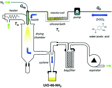 | ||
| Fig. 6 Schematic illustration of the set-up for the aqueous continuous flow spray-drying synthesis of UiO-66-NH2. Reprinted with permission from ref. 58 published by the Royal Society of Chemistry. | ||
The relationship between the density of a compressed material and the pressure imposed on the shaped material is an important issue for the shaping of MOFs by pressing. It should be noted that the structural flexibility of MOFs is different from the compressibility of MOFs. The structural flexibility is a microscopic property, which depends largely on the bond lengths and bond angles in the framework structures of MOFs. The compressibility is a macroscopic property, largely depending on the intergranular gap, size and shape of the particles. Pressing is a macroscopic action, and it is closely related to the compressibility of MOFs. Lupu et al. reported the hydrogen adsorption properties of a compressed sample of MIL-101.120 A powder sample of MIL-101 was pressed into pellets with different densities using a manual hydraulic machine. According to the densities of the sample obtained at different pressures, the authors found that the packing density of MIL-101 did not increase linearly with pressure. At normal temperature and pressure, the density of a powder sample of MIL-101 is 0.19 g cm−3. Similarly, Tagliabue et al. obtained a pellet-shaped sample of Ni-MOF-74 with a diameter of ≈1 cm and a thickness of ≈0.1 cm when the pressure was in the range of 0.1–1 GPa.121 It was also found that the density of the shaped sample did not increase linearly with the applied pressure, and the N2 adsorption capacity of the Ni-MOF-74 sample was completely lost after it was pressed under 1 GPa.
The influence of pressure on the properties of the compressed material is complicated. On the one hand, the compression operation has a positive effect on the performances of MOFs. Firstly, pressing increases the surface hardness and mechanical strength of MOFs. It was reported that the wafers of ZIF-8 and MIL-53(Al) could be obtained by mechanically compressing the original powder samples without any adhesive.122 The authors demonstrated that the MOF wafers were very durable and capable of withstanding pressure swing adsorption (PSA) cycles with a high pressure up to 18 bar. Secondly, the compression operation may increase the catalytic activity of MOFs. Bazer-Bachi et al. reported that the pressurization operation had an opposite effect on the inner pore surface area to that on the outer surface area of shaped MOFs (Fig. 7).95 The pressurization operation could result in a decrease in the intrinsic specific surface area for the MOF material, while the exposed area of the outer surface of the shaped materials could increase simultaneously. It was found that the shaped sample had a higher catalytic activity. The authors interpreted that the catalytically active sites were located on the outer surface of the material, while the compression behavior induced the formation of new active sites on the outer surface of the material.
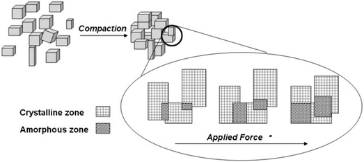 | ||
| Fig. 7 Schematic view of the impact of compression on the inner pore surface area and the outer surface of a MOF sample. Reprinted with permission from ref. 95. Copyright 2014 Elsevier. | ||
On the other hand, the compression operation has an adverse effect on the structure and properties of MOFs. Generally, the adsorption performance of a powder sample of the MOF is different from that of a pressing-shaped MOF sample to some extent. Ardelean et al. investigated the gas adsorption properties of a pressing-shaped sample of MIL-101.120 The nitrogen and hydrogen adsorption studies indicated that a mechanical pressure applied to prepare the shaped MIL-101 sample induced an irreversible structural transformation of the MOF. The specific surface area, pore volume, and hydrogen adsorption capacity all reduced after compressing the MOF sample. Infrared spectroscopy results also showed that the compression significantly affected the characteristic vibration of phenyl groups in MIL-101 and the coordination modes between carboxylate groups of the ligands with the Cr3+ ions. It was demonstrated by Bazer-Bachi et al. that some MOFs could convert into amorphous materials under certain pressures.95 Two well-known MOFs, ZIF-8 and HKUST-1, were studied in this work. The authors found that compression had an adverse effect on the micro-porosity of the MOFs. Besides, the same pressure affected differently the adsorption properties of the two materials. Ribeiro et al. demonstrated that a mechanical compression had a greater effect on the crystalline structure of MIL-53(Al) than the effect on ZIF-8.122 After pressing, the loss of surface area and pore volume is only 7% for ZIF-8, while the surface area and pore volume of MIL-53(Al) were reduced by 32% and 24%, respectively. Besides, X-ray diffraction experiments indicated that the structural change caused by the compression operation is irreversible, and the decrease in crystallinity is proportional to the applied external force. Nevertheless, there are also some MOF materials with structures and adsorption properties hardly affected by a compression operation. For example, Tagliabue et al. demonstrated that the properties of Ni-MOF-74 could be substantially unchanged after a compression treatment, as suggested by the adsorption data.121 A powder sample of Ni-MOF-74 was prepared by the solvothermal reaction, and two compressed samples were obtained from applying a 0.1 and 1 GPa pressure on the Ni-MOF-74 powder sample without adhesives. Gas adsorption measurements for the 0.1 GPa shaped Ni-MOF-74 samples indicated a CH4 adsorption capacity of 129 cm3 g−1 at 303 K and 34 bar, which was very close to the value for the powder sample of Ni-MOF-74.
2.2. Templated shaping
Templated shaping is a technique for the shaping of MOFs with the aid of substrate materials. The sol–gel method and electrospinning method are two commonly used substrate-templated shaping methods. In such a technique, the MOFs are generally shaped with the polymeric additives by various processes, such as sol–gel casting, adhesive addition, surfactant-assisted dip coating and freeze-drying. The high stability of the additives is the key for the successful preparation of shaped MOFs.Nanocellulose has been extensively studied for its low density, low cost, non-toxicity and regenerability. The ultra-high toughness of this material offers a platform for the fabrication of MOF–cellulose composites as flexible materials containing hierarchical pores.124–126 Zhu et al. reported the preparation of the cellulose–MOF hybrid aerogels for three MOFs (Fig. 8),123 namely ZIF-8,84,127 UiO-66,128 and MIL-100(Fe).129 The hybrid aerogel was obtained from the MOF particles, aldehyde modified cellulose nanocrystals (CHO-CNCs) and hydrazide modified carboxymethyl cellulose (NHNH2-CMC). The MOF particles were first mixed with CHO-CNCs to form a stable colloidal suspension in water. The resulting colloidal suspension was then added into an aqueous solution of NHNH2-CMC, leading to the formation of hydrazone linkages between the aldehyde groups of CHO-CNCs and the hydrazide groups of NHNH2-CMC. Finally, a CNC–CMC–MOF hybrid aerogel was obtained after the suspension was frozen and freeze-dried. In such a manner, the MOF particles were trapped in the crosslinked cellulose network. The authors believed that the interactions between the MOF particles and the cellulose were physical entanglement and van der Waals interactions.130 It was also demonstrated that the encapsulation of MOF particles by the cellulose did not block the pores of MOFs or lead to the collapse of the MOF structure. Hybrid all–CNC–MOF aerogels were similarly prepared by the MOF particles, CHO-CNCs and hydrazide-modified CNCs (NHNH2-CNCs) instead of NHNH2-CMC. However, it was found that the all–CNC–MOF aerogels showed more loose structures than the CNC–CMC–MOF hybrid aerogels and fell apart easily. The poor mechanical stability of the all–CNC–MOF aerogels was attributed to the fact that the CNC–CNC crosslinking was sterically hindered by the rigid crystalline structures of both the MOF particles and CNCs.
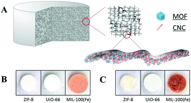 | ||
Fig. 8 (A) The schematic representation of a MOF–cellulose hybrid aerogel. Photographs of (B) CNC–CMC–MOF based hybrid aerogels (CNC![[thin space (1/6-em)]](https://www.rsc.org/images/entities/char_2009.gif) : :![[thin space (1/6-em)]](https://www.rsc.org/images/entities/char_2009.gif) CMC CMC![[thin space (1/6-em)]](https://www.rsc.org/images/entities/char_2009.gif) : :![[thin space (1/6-em)]](https://www.rsc.org/images/entities/char_2009.gif) MOF = 1 MOF = 1![[thin space (1/6-em)]](https://www.rsc.org/images/entities/char_2009.gif) : :![[thin space (1/6-em)]](https://www.rsc.org/images/entities/char_2009.gif) 1 1![[thin space (1/6-em)]](https://www.rsc.org/images/entities/char_2009.gif) : :![[thin space (1/6-em)]](https://www.rsc.org/images/entities/char_2009.gif) 1 by weight), and (C) all–CNC–MOF based hybrid aerogels (CNC 1 by weight), and (C) all–CNC–MOF based hybrid aerogels (CNC![[thin space (1/6-em)]](https://www.rsc.org/images/entities/char_2009.gif) : :![[thin space (1/6-em)]](https://www.rsc.org/images/entities/char_2009.gif) CNC CNC![[thin space (1/6-em)]](https://www.rsc.org/images/entities/char_2009.gif) : :![[thin space (1/6-em)]](https://www.rsc.org/images/entities/char_2009.gif) MOF = 1 MOF = 1![[thin space (1/6-em)]](https://www.rsc.org/images/entities/char_2009.gif) : :![[thin space (1/6-em)]](https://www.rsc.org/images/entities/char_2009.gif) 1 1![[thin space (1/6-em)]](https://www.rsc.org/images/entities/char_2009.gif) : :![[thin space (1/6-em)]](https://www.rsc.org/images/entities/char_2009.gif) 1 by weight); aerogels are about 7 mm in diameter and 5 mm in height. Reprinted with permission from ref. 123. Copyright 2016 John Wiley and Sons. 1 by weight); aerogels are about 7 mm in diameter and 5 mm in height. Reprinted with permission from ref. 123. Copyright 2016 John Wiley and Sons. | ||
Although mechanically stable cellulose–MOF hybrid aerogels can be prepared by crosslinking of CNC and CMC, a pre-modification of CNC and CMC with aldehyde or hydrazide groups is necessary for the crosslinking. Alternatively, Ma et al. reported that MOF-BC composite aerogels with a hierarchical porosity could be directly prepared by integrating the MOF, ZIF-8 or UiO-66, with the bacterial cellulose (BC), a cost-effective, lightweight and commercially available porous material.131 The pre-prepared BC aerogels in a specific shape were firstly mixed with a solution of metal ions, and then an organic ligand solution was added. The mixture was then placed in a condition which was suitable for the growth of MOFs. The authors believed that the abundant hydroxyl groups of BC nanofibers could preferentially interact with the metal ions through weak interactions, such as coordination bonding and electrostatic interactions, which was followed by the nucleation of MOF nanoparticles on the surface of BC nanofibers. As a template, the BC nanofibers in this synthetic method not only enhanced the high porosity and mechanical flexibility of the composite aerogels, but also contributed to the low density, hierarchical porosity, large surface area, and high mass transfer efficiency of the final MOF-BC composite aerogel sponge. In another work, Yang et al. reported the growth of ZIF-67 in the 3D hydrogel of reduced graphene oxide (rGO) to obtain a 3D rGO/ZIF-67 aerogel (Fig. 9).132 The 3D rGO hydrogel was obtained by reducing the GO nanosheets dispersed in water with an NH3·H2O solution in a Teflon-lined autoclave at 180 °C for 24 h. The resulting rGO hydrogel was then added into a methanol solution of Co(NO3)2. After stirring for 12 hours, the methanol solution of Co(NO3)2 was poured out, and then a methanol solution of the ligand 2-methylimidazole was added. The mixture was stirred for 12 h, resulting in the formation of ZIF-67 in the rGO hydrogel. After washing with water and freeze-drying of the hydrogel, the final rGO/ZIF-67 aerogel was obtained, which showed a high adsorption capacity for cationic dyes (crystal violet, CV) and anionic dyes (methyl orange, MO) in water.
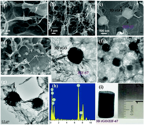 | ||
| Fig. 9 The SEM images of (a and b) 3D rGO aerogel and (c and d) 3D rGO/ZIF-67 aerogel, and the TEM (e, f and g), (h) EDX and (i) digital photographs of the 3D rGO/ZIF-67 aerogel. Reprinted with permission from ref. 132. Copyright 2018 Elsevier. | ||
Wang and co-workers developed a facile method to prepare hierarchically porous foams consisting of MOF nanoparticles and CMC.133 The MOF nanoparticles were first dispersed in a DMF/acetone solvent by ultrasonication, and acetone was later removed by rotary evaporation. It was previously demonstrated by Cohen and co-workers that the use of a solvent with low viscosity like acetone could facilitate the preparation of a homogeneous MOF dispersion, and subsequent addition of a polymer solution, such as polyvinylidene fluoride (PVDF) in DF or N-methylpyrrolidone (NMP), into the homogeneous MOF dispersion could produce a homogeneous casting solution.134 After mixing the MOF dispersion with a transparent CMC aqueous solution by stirring, MOF@CMC foam could be obtained by freeze-drying of the MOF-CMC fluid in a cylinder-shape mold. The authors successfully prepared MOF@CMC foams for six representative MOFs (Fig. 10), namely HKUST-1, ZIF-8, Mg-MOF-74, Zn-MOF-74, UIO-66, and NH2-UiO-66, and believed that this synthetic strategy was a general method for the shaping of MOFs and even many other crystalline porous solids.
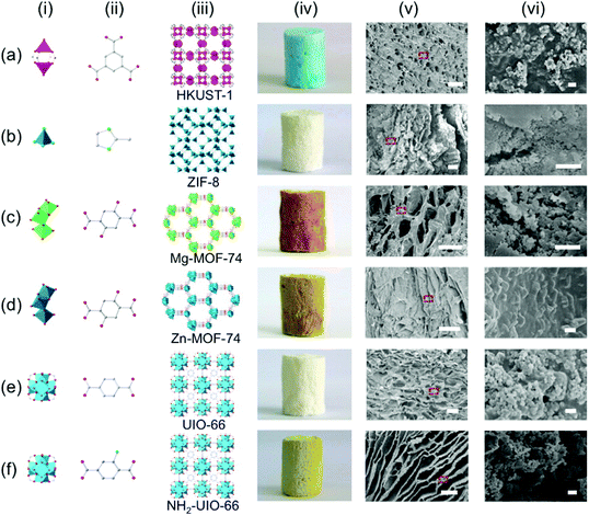 | ||
| Fig. 10 The crystal structures of HKUST-1, ZIF-8, Mg-MOF-74, Zn-MOF-74, UIO-66, and NH2-UiO-66, and the optical photos and SEM images of the MOF@CMC foams based on these MOFs. The scale bars are 100 μm in v and 1 μm in vi. Reprinted with permission from ref. 133. Copyright 2016 American Chemical Society. | ||
Achieving a high MOF loading in the MOF-based fiber sorbents is a challenging goal. MOF crystals and polymers are used together for the electrospinning, and it is a facile route to integrate MOF particles into a composite fiber. Rose et al. presented a versatile approach for the integration of MOF particles into polymer/MOF composite fibers to obtain the homogeneous textile-like layers by electrospinning.138 A high loading of HKUST-1 in the fibers up to 80 wt% was achieved. The general procedure for the preparation of the composite fiber is described as follows. The first step was the preparation of MOF-polymer suspension in an organic solvent (polystyrene in THF, PVP in ethanol, or PAN in DMF). After dissolving the polymer in an organic solvent, the powder sample of MOFs was added and the resulting mixture was stirred to obtain a homogeneous suspension, which was then filled in a syringe for further processing. In the second step, two ends of the syringe loaded with the suspension were connected by a syringe pump and a stainless-steel needle, respectively. At the same time, a generator was used to provide a high voltage on the stainless-steel needle. The MOF-polymer composite fiber was finally produced by jet spinning of the needle under the electric field after the evaporation of the solvent. In this technique, the diameter of the composite fiber can be controlled by adjusting the concentration of the polymer solution. The surface polarity of the MOF material and the polarity of the polymer significantly affected the loading of the MOF.
Wang et al. reported that a flexible MOF nanofiber membrane (NFM) with hierarchical pores could be prepared by the colloid-electrospinning technology.139 The UiO-66-(COOH)2 nanoparticles, containing rich carboxyl groups, were embedded in the PAN nanofibers. The loading of the UiO-66-(COOH)2 nanoparticles was as high as 60% by weight in the composite PAN/UiO-66-(COOH)2 NFM. In another example, Zhang et al. prepared a PAN/HKUST-1@HKUST-1 NFM (named HKUST-1 NFM for short) by the seeded growth of HKUST-1 crystals on the skeleton of a PAN/HKUST-1 NFM, which was pre-fabricated by the electrospinning technique (Fig. 11).140 The fiber based NFM synthesized in this strategy was stable and uniform, and the HKUST-1 loading was high up to 82 wt%.
 | ||
| Fig. 11 Schematic illustration of electrospun PAN/HKUST-1composite fibers used as a skeleton to prepare a self-supported and flexible HKUST-1 nanofibrous membrane (NFM) with ultrahigh HKUST-1 loading and stable and uniform HKUST-1 growth. Reprinted with permission from ref. 140. Copyright 2018 American Chemical Society. | ||
The electrospinning process can also be used to improve the properties of the resulting composite fibers. Armstrong et al. successfully demonstrated that the hydrothermal stability of HKUST-1 could be greatly improved after being coated with a thin layer of hydrophobic polystyrene by electrospinning.141 Dahal et al. introduced ZIF-8 into a highly porous PAN-based carbon nanofiber by the electrospinning technique, and the resulting material showed high performance as a supercapacitor electrode.142 Zhang et al. prepared a ZIF-67/PAN nanofiber by the electrospinning technique, which was subsequently treated by pyrolysis at high temperature (800 °C), resulting in a composite named C-ZIF-67/PAN-800.143 The authors demonstrated that a glassy carbon electrode modified by C-ZIF-67/PAN-800 could be used to construct high performance sensors for the detection of hydroquinone and catechol. Zhang et al. reported that nanocrystals of four MOFs (ZIF-8, Mg-MOF-74, UiO-66-NH2 and MOF-199) could be processed into nanofibrous filters (MOFilters) with the polymer PAN, polystyrene or PVP.144 The obtained MOFilters showed high efficiencies to remove fine particulates with aerodynamic diameters below 2.5 μm (PM2.5) and 10 μm (PM10) in air.
2.3. Self-shaping
In the above-mentioned cases, the shaping of MOFs is achieved either by an external force or by the aid of another substance. However, the high pressure or the addition of another substance sometimes could lead to partial damage or even complete collapse of the porous MOF materials, resulting in the decrease of their adsorption capacities. In contrast, the self-shaping method could effectively circumvent this issue. There are two characteristics for the self-shaping technology. Firstly, the influence from the other species, such as templates, additives and binders, on the structural stability, porosity and function of the MOF materials can be excluded. Secondly, the cost to produce shaped MOFs is greatly cut down. Therefore, an in-depth development of the self-shaping technology may play an important role in promoting the practical applications of MOFs.So far, there are only a few reports on the self-shaping of MOFs. In addition to the self-shaping method, the structure and adsorption properties of the self-shaped MOFs are also the focus of relevant research. Fairen-Jimenez and co-workers have done some pioneering studies on the self-shaping of MOFs.145–148 In 2015, they synthesized a mechanically and chemically stable ZIF-8 monolith by the self-shaping method. The ZIF-8 crystals were prepared by stirring a mixture of 2-methylimidazole (ligand for ZIF-8) and Zn(NO3)·6H2O in ethanol at room temperature for 2 hours, a method reported by Cravillon et al.149 The second step is the post-treatment of the resulting ZIF-8 sample. After centrifugation and washing with ethanol to collect a white product, four different methods were used to further treat the ZIF-8 sample: (1) some of the primary sample of ZIF-8 was dried at 100 °C overnight in a vacuum oven to obtain ZIF-8HT (HT stands for high temperature); (2) some of the primary sample of ZIF-8 was dried at room temperature overnight to obtain ZIF-8LT (LT stands for low temperature); (3) the ZIF-8LT sample was further evacuated in a vacuum oven overnight at 100 °C to yield ZIF-8LT-HT; (4) some of the primary sample of ZIF-8 was dispersed in ethanol, and the starting materials of 2-methylimidazole and Zn(NO3)·6H2O were then added into the solution; after the resulting mixture was ultrasonicated for 10 minutes at room temperature, the solid was collected by centrifuging and washing with ethanol. The collected solid was dried at room temperature overnight, resulting in ZIF-8ER (ER stands for the extended reaction). Interestingly, it was found that the white pellets of ZIF-8HT easily disaggregated into a typical powder sample of ZIF-8, but ZIF-8LT, ZIF-8LT-HT and ZIF-8ER remained as transparent monolithic structures (Fig. 12). The authors proposed that new ZIF-8 was formed during the drying process of the primary ZIF-8 at room temperature, and the newly formed ZIF-8 acted as a binder of the primary ZIF-8 particles because there were residuary reactants (2-methylimidazole and Zn2+ ions) within the sample and the mild drying process allowed the extension of the polymerization reaction. On the other hand, the slow drying process could benefit to reduce the stress around the vapor–liquid meniscus during the evaporation of the solvent found in the interstitial spaces between primary ZIF-8 particles. The ZIF-8ER monolith, which was obtained with higher amounts of residuary reactants within the sample in the room temperature drying process, showed significantly higher elastic modulus than the monoliths of ZIF-8LT or ZIF-8LT-HT, further supporting their hypothesis. In addition, N2 adsorption studies revealed that the ZIF-8 monoliths retained the characteristic porosity of ZIF-8, and their bulk densities and volumetric N2 adsorption capacities were three times higher than those of a powder sample of ZIF-8. In 2018, Zhang and co-workers prepared large transparent blocks of MAF-4/ZIF-8 nanocrystals using a similar procedure mentioned above.150 The MAF-4/ZIF-8 block shows a high optical transmittance (69% to 84%) in the visible light region (400 nm to 700 nm) as the typical optical ceramics Nd:YAG does, and thus it was regarded as a metal–organic optical ceramic (MOOC). The author also demonstrated that the MOOC exhibited amplified spontaneous emission with a very low energy-density threshold after a laser dye (sulforhodamine 640) was encapsulated inside the pore of MAF-4/ZIF-8 or into the crystal defect during the synthesis of the MOF nanocrystals.
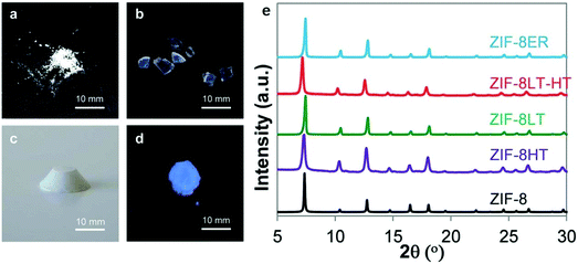 | ||
| Fig. 12 (Left) Optical photos of (a) ZIF-8HT; (b) ZIF-8LT; (c) ZIF-8ER and (d) ZIF-8ER samples under 365 nm UV light. (e) PXRD patterns of the different ZIF-8 samples alongside a simulated pattern for ZIF-8. Adapted with permission from ref. 145 published by the Royal Society of Chemistry. | ||
Later, with a similar method, Fairen-Jimenez and co-workers prepared another monolithic MOF, monoHKUST-1, without binders and/or high pressures.146 The mother solution containing the primary HKUST-1 particles was centrifuged at the beginning of the reaction to obtain a densified solid, which was also regarded as a gel. After slowly drying at room temperature, a dense, glassy-look monolith of HKUST-1 was obtained. The drying temperature was critical to achieve the final morphology of the monolith. In contrast, a powder sample of HKUST-1 (powdHKUST-1) was obtained if the dense gel was dried at high temperature. It was believed that the fast removal of the solvent between primary HKUST-1 particles did not allow the gel macrostructure to be maintained, and, during the slow drying period, the residuary precursors started nucleating at the interface and experienced an epitaxial growth within the primary particles. Notably, the shaped material of monoHKUST-1 showed a high volumetric methane adsorption capacity up to 259 cm3 (STP) cm−3 at 65 bar, which was the highest value reported to date for conformed shape porous solids. In addition, nanoindentation tests revealed that the hardness of monoHKUST-1 was over twice the conventional sample of HKUST-1.
Although monoHKUST-1 showed a high volumetric methane adsorption capacity at high pressure, its high microporosity and a strong physical interaction with natural gas at low pressure results in a compromised working capacity for CH4 storage of monoHKUST-1. Besides, HKUST-1 loses crystallinity and adsorption capacity under moisture under ambient conditions. Therefore, Fairen-Jimenez and co-workers developed the synthetic procedures for monolithic samples of a hydrolytically stable MOF, UiO-66.147 A UiO-66 gel with 10 nm primary MOF particles was first prepared by the modification of a previously reported synthesis method for UiO-66,151 and four different methods were used to further treat the primary MOF particles, and macroscopic monolith samples of UiO-66 were obtained (Fig. 13). monoUiO-66_A was obtained by washing the primary MOF particles with ethanol and drying at 200 °C. monoUiO-66_B was prepared by washing the primary MOF particles with ethanol but the sample was dried at 30 °C. Optically transparent monoUiO-66_C was obtained by the primary MOF particles with DMF and drying at 30 °C. The preparation of monoUiO-66_D is similar to that of monoUiO-66_C, except an extended (180 min) centrifugation step was applied to check the effects of primary particle densification prior to drying. The authors demonstrated that these relatively minor differences in synthesis resulted in interesting changes in the physical properties of the resulting monolith samples of UiO-66, such as density, fluorescence and adsorption properties. All the resulting monoliths show both micropores and mesopores. The mesopore volumes follow the trend monoUiO-66_A > monoUiO-66_B > monoUiO-66_C > monoUiO-66_D. However, the volumetric gas uptake for both CH4 and CO2 follows the same trend: monoUiO-66_D ≈ monoUiO-66_C ≫ monoUiO-66_B ≈ monoUiO-66_A. monoUiO-66_D showed an outstanding adsorption capacity among the four samples. The CH4 uptakes are 211 and 296 cm3 (STP) cm−3 at 65 and 100 bar, respectively, and the CO2 uptake is 284 cm3 (STP) cm−3 at 40 bar.
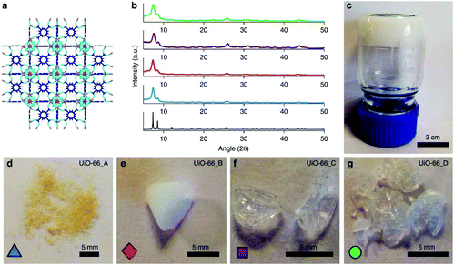 | ||
| Fig. 13 Crystalline structure and optical images of UiO-66 gel and monoliths. (a) Graphical representation of the microporous crystal structure of UiO-66 with purple, sky blue, navy blue and white sticks representing zirconium, oxygen, carbon and hydrogen atoms, respectively. (b) Comparison of the simulated XRD pattern of UiO-66 with PXRD patterns of monoUiO-66 samples (monoUiO-66_A; blue, monoUiO-66_B; red, monoUiO-66_C; purple, monoUiO-66_D; green). (c) UiO-66 gel used for synthesizing monoliths. The optical photos of (d) monoUiO-66_A, (e) monoUiO-66_B, (f) monoUiO-66_C, and (g) monoUiO-66_D. Reprinted with permission from ref. 147. Copyright 2019 Springer Nature. | ||
2.4. Shaping by in situ growth on substrates
In most cases in the above-mentioned methods, the MOF samples to be shaped are pre-synthesized, and the shaping processes are after the syntheses of MOFs. Another important shaping method of MOFs is the in situ growth of MOF crystals on certain substrates. When the synthesis reaction is completed, a supported MOF is obtained. The method is commonly used in the fabrication of a MOF membrane.152–155 Though some works have been reported on in situ growing MOF crystals on the substrates without any treatment, the pre-treatment of substrates with various procedures has proved to be an effective method to induce the nucleation of MOF crystals on the substrates. Some representative examples are introduced below.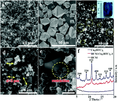 | ||
| Fig. 14 SEM micrographs of HCM (a), HKUST-1 crystals (b), and HCM-HKUST-1–3 (c, d and e). (f) XRD patterns of HCM, HKUST-1, and HCM-HKUST-1–3. Reprinted with permission from ref. 156. Copyright 2012 American Chemical Society. | ||
Similarly, the in situ growth of UiO-66 crystals in the macroporous structure of a polyurethane foam (PUF) was reported by Pinto et al.157 The polyurethane foam was directly immersed in the precursor solution of UiO-66, and a UiO-66-PUF composite could be successfully prepared by a solvothermal reaction of precursor solution at optimized reaction temperature and duration. The resuling composite showed flexibility, micropores from the PUF and micropores from the MOF crystals. This method was regarded as an alternative to obtain nonpowder MOF materials. Different from porous carbon or polyurethane foam, pulp fibers are a class of materials with spatially three-dimensional structures composed of cellulose or hemicellulose. A good dispersity in solvent is an important advantage for the pulp fibers, which can be mixed with the solution of MOF precursors to form a homogeneous phase. Küsgens et al. reported the in situ growth of HKUST-1 on pulp fibers.158 The ligand 1,3,5-benzenetricarboxylic acid and Cu(NO3)2 were first dissolved in a mixed solution of EtOH and DMF. Then, the pulp fibers were added into the prepared solution, resulting in a slurry like mixture. The slurry was gradually heated to 358 K in a Teflon-lined steel vessel and maintained at this temperature for 24 hours. Finally, the product was collected by filtering and washing. Three pulp samples, namely, CTMP (chemithermomechanical pulp), a bleached southern pine kraft pulp and an unbleached kraft pulp, were used for such an experiment. The product obtained from the experiment with CTMP as pulp fibers showed a high MOF loading (19.95 wt%). The SEM image of the product showed that the HKUST-1 crystals were regularly distributed over the CTMP fibers. In contrast, when the bleached kraft pulp was used in the experiment, almost no MOF crystal was observed on the pulp fibers. The authors interpreted that the contents of lignin in the three pulp samples were different, and the structure of lignin contains carbonyl or carboxylic acid groups, which could induce the in situ growth of HKUST-1 crystals on the pulp fibers.
The in situ growth of MOF crystals on blank substrates represents a facile method to shape the MOF powder samples. The preparation is commonly achieved by the solvothermal reactions similar to the syntheses of MOF powder samples. The resulting products not only inherit the properties of the original substrate materials, such as macroporosity and flexibility, but also integrate the high adsorption capacity and/or selective adsorption performance of the microporous MOFs. However, the stability of the substrate/MOF bonding in long-term repeated use was seldom investigated in the literature, and achieving a high loading of MOF particles in the final shaped composites is still challenging.
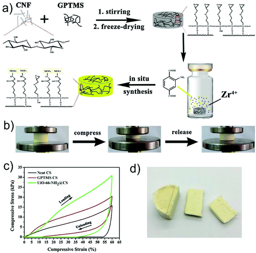 | ||
| Fig. 15 (a) Schematic illustration for the preparation of a UiO-66-NH2-loaded cellulose sponge; (b) the photos of the MOF-loaded cellulose sponge during the compression process; (c) compressive stress–strain curves of neat cellulose sponge (CS), GPTMS modified cellulose sponge (GPTMS CS) and UiO-66-NH2-loaded cellulose sponge (UiO-66-NH2@CS); (d) a digital photograph of the UiO-66-NH2-loaded cellulose sponge. Reprinted with permission from ref. 164. Copyright 2019 Elsevier. | ||
A cellulose paper@MOF-5 composite material was reported by Yang et al., which was prepared by the in situ growth of MOF-5 crystals onto the precipitated calcium carbonate (PCC) filled cellulose paper.166 PCC is widely used in common paper products as an inorganic filler because the introduction of this material is cost-effective and improves the optical properties and printability of paper. It was expected that after the introduction of PCC some bonding between the cellulose fibers in a paper could be interrupted, and thus expose more hydroxyl groups on the surface of cellulose paper. More MOF-5 crystals in sizes of 20–100 μm covering the PCC filled cellulose paper were observed than that for the paper without a PCC filler. It was explained that when the PCC filled cellulose paper was added to the reaction mixture for the preparation of MOF-5, the abundant hydroxyl groups on the surface of cellulose paper might react with one carboxyl group of the ligand 1,4-benzenedicarboxylic acid (H2BDC) by the formation of an ester group and another carboxyl group of the ligand as exposed on the surface, which induced the nucleation of the MOF crystals on the cellulose paper.
Compared with the traditional synthetic organic polymers, the biopolymer chitin is an excellent starting material as a substrate for the growth of MOFs due to its abundant functional groups, which could interact with metal ions. Wisser et al. reported biological chitin–MOF composites with hierarchical pores for air-filtration applications.167 The chitin substrate with a porous fiber structure was extracted from a marine sponge as a non-toxic, biodegradable, and low-weight support material for MOF deposition, which could interact with metal ions by strong adsorption due to its high content of hydroxyl and acetamido groups. The chitin substrate was first immersed in an aqueous Cu(NO3)2 solution, in which the metal ions were allowed to interact with the functional groups of chitin. Then, the pre-treated substrate was transferred to an ethanol solution of H3BTC to produce the MOF, HKUST-1, by a low-temperature solvothermal method. The prepared HKUST-1-chitin composite showed a hierarchically porous structure, wherein the loading of HKUST-1 was high up to 53% (w/w). The SEM images showed that the MOF crystals were preferentially formed inside the hollow fibers, and thus it was believed that the MOF crystals could be largely protected from external mechanical stress and abrasion. The authors also demonstrated a high ammonia capture capacity of the HKUST-1-chitin composite, which may potentially serve as a robust adsorption material in air filters.
Cellulose nanofibers are promising natural nanomaterials for many applications. After wood pulp is treated with 2,2,6,6-tetramethylpiperidin 1-oxyl (TEMPO), the TEMPO oxidized cellulose nanofibers (TOCNs) with rich carboxy groups can be produced. Matsumoto and Kitaoka reported the preparation of ZIF-90-TOCN nanocomposites and fabricated high-performance gas-separation materials based on the ZIF-90-TOCN nanocomposites and common filter papers.168 An aqueous TOCN suspension was first prepared from softwood Kraft pulp by TEMPO oxidation. The surface of the TOCNs was functionalized by sodium carboxylate groups (COO−Na+). The aqueous TOCN suspension was then mixed with Zn(NO3)2·6H2O solution. As there was a high density of carboxyl groups on the surface of TOCN, the carboxylates reacted with zinc(II) cations to form metal–carboxylate complexes.169,170 After centrifugation at room temperature for 60 minutes and washing with solvent, a Zn−TOCN gel was produced. The resulting Zn−TOCN gel was then suspended in the precursor solution for the synthesis of ZIF-90. After a solvothermal reaction of the mixture, a ZIF-90-TOCN nanocomposite was collected. The ZIF-90-TOCN nanocomposite was further fabricated into a ZIF-90-TOCN film by simply filtering a dilute suspension of the ZIF-90-TOCN nanocomposite in methanol with a commercial filter paper under reduced pressure. The authors investigated the CO2/CH4 separation performance of the resulting ZIF-90-TOCN film, and demonstrated a high CO2/CH4 permeance selectivity (123), which was attributed to the molecular-sieving effect of the MOF and the strong affinity between MOF and TOCNs.
The coating of the metal oxides on the substrates is another pre-treatment method. Zhao et al. found that the nucleation of MOFs on the fiber mat could be promoted by a nanoscale coating of Al2O3 on the surface of a nonwoven fiber mat with the atomic layer deposition (ALD) technique.171 Polypropylene (PP) fibers in a nonwoven mat were first coated with ALD Al2O3 at 60 °C for 200 cycles, and then the Al2O3-coated polymer fibers were placed in the precursor solution of HKUST-1 for a solvothermal reaction at 120 °C for 20 hours. It was found that HKUST-1 crystals were densely and homogeneously formed on the Al2O3-coated polymer fibers (Fig. 16), and the resulting material was named the HKUST-1-PP/ALD fiber mat. A control experiment was also carried out for the growth of HKUST-1 on a PP fiber mat without any pre-treatment. The HKUST-1 crystals were formed inside the matrix of PP fibers instead of on the surface of PP fibers, indicating a homogeneous nucleation of the MOF occurring in the reaction solution. This result also suggested that the coating of Al2O3 on the PP fibers improved the reactivity of the fiber surfaces for the nucleation of MOF crystals. Compressed air blowing tests were performed to assess the bonding strength between MOF crystals and the PP fibers in the HKUST-1-PP/ALD fiber mat, which showed a ∼15% mass loss and that the mass loss stabilized within a few minutes. Afterwards, bending and rubbing tests were carried out, and the results showed no more noticeable MOF detachment, suggesting a high mechanical stability of the MOF-PP/ALD fiber mat. The authors also found that the HKUST-1-PP/ALD fiber mat could effectively remove hazardous gas (e.g., NH3 and H2S) in air, and the synthetic approach could be applicable to a wide range of polymer fibers (e.g., PP, PET, cotton) and MOFs (e.g., HKUST-1, MOF-74, and UiO-66).
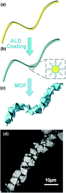 | ||
| Fig. 16 Schematic illustration of (a) the polymer fiber substrate, (b) the Al2O3-coated polymer fiber via atomic layer deposition (the cross section in the dashed square illustrates the conformal coating of Al2O3 with hydroxyl surface termination), and (c) the MOFs integrated on an Al2O3-coated polymer fiber using solvothermal MOF synthesis. (d) the SEM image of HKUST-1 MOF crystals grown on an Al2O3-coated polypropylene fiber (MOF-PP/ALD). Reprinted with permission from ref. 171. Copyright 2014 John Wiley and Sons. | ||
2.5. Shaping with sacrificial materials
In some cases, the growth of MOF crystals on a substrate involves the conversion of a sacrificial material into the MOF, and the sacrificial material is either the substrate itself or another substance on the substrate. For instance, Bechelany et al. reported the growth of ZIF-8 or MIL-53-NH2 on the nanofiber mats, which were coated with a thin layer of ZnO or Al2O3 as the sacrificial material for producing MOFs.172 The PAN fibers with an external diameter of ∼250 ± 50 nm were first prepared by electrospinning. Then, the deposition of the ZnO or Al2O3 layers on the PAN fibers was performed by the ALD technique, which could well control the thickness of the deposited oxide layer by varying the number of deposition cycles. An ALD deposition with 250 cycles produced a ZnO layer with a thickness of 50 nm and an Al2O3 layer with a thickness of 42 nm on the PAN fibers, respectively. After the ZnO-coated nanofiber mats were placed in a methanolic solution of 2-mim (imidazolium anions) at 100 °C for 1.5 hours, a layer of ZIF-8 crystals in a size of 200 nm was homogeneously formed on the nanofibers, resulting in the PAN/ZnO/ZIF-8 composite material (Fig. 17a). Obviously, ZnO was a sacrificial material for the formation of ZIF-8 crystals, because there was no other source of zinc cation in the reaction for the synthesis of ZIF-8 except ZnO. The PXRD patterns also confirmed that about 83% of ZnO converted to ZIF-8. Similarly, MIL-53-NH2 crystals in a size of 200 nm uniformly covering the PAN nanofibers (the PAN/Al2O3/MIL-53-NH2 composite material) were obtained by placing the Al2O3-coated nanofiber mats in an aqueous solution of 2-aminoterephthalic acid (H2BDC-NH2, the free ligand of MIL-53-NH2) after the reaction at 100 °C for 1.5 hours (Fig. 17b). The conversion of Al2O3 to MIL-53-NH2 was about 61%. The authors believed that during the conversion processes composite materials were formed, and the residual metal oxides in the composite materials might serve as a link between the MOFs and the PAN nanofibers. It was also demonstrated that the PAN nanofiber supported MOF crystals could be tuned in crystal size, morphology, orientation and loading by varying the solvothermal conditions.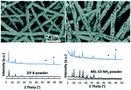 | ||
| Fig. 17 SEM images and the corresponding XRD patterns of: (a) PAN/ZnO/ZIF-8 and (b) PAN/Al2O3/MIL-53-NH2 composite materials; diffraction peaks of Al-foil are marked with (*) and diffraction patterns of ZIF-8 and MIL-53-NH2 reference powder samples are presented for comparison. Reprinted with permission from ref. 172 published by the Royal Society of Chemistry. | ||
Recently, Zhu and co-workers reported the growth of four typical MOFs (ZIF-8, ZIF-67, HKUST-1, and Fe-BTC) inside low-cost chitosan beads with metal hydroxides or oxides as sacrificial materials.173 Due to the insolubility of chitosan in alkali solution,105 chitosan beads containing metal hydroxides or oxides could be formed by adding a acetic acid/water solution of chitosan and metal salts into a NaOH solution drop-by-drop (Fig. 18). Since there exists coordination interaction between metal ions and amino groups of chitosan, the metal ions were expected to be uniformly located in chitosan, which transformed into metal hydroxides or oxides after the formation of beads. The metal hydroxide(or oxide)-chitosan composite beads were then immersed in the solutions of organic ligands for hydro/solvothermal reactions, producing MOF particles uniformly dispersed inside the chitosan beads. The authors also demonstrated high adsorption capacities of the MOF-chitosan beads for antibiotic tetracycline in water.
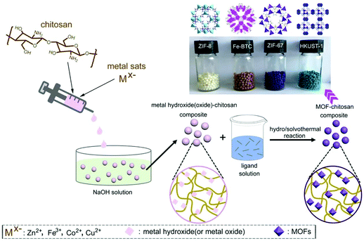 | ||
| Fig. 18 Schematic presentation of the preparation of MOF-chitosan beads. Reprinted with permission from ref. 173. Copyright 2020 Elsevier. | ||
Many works have been reported on the fabrication of MOF membranes, which are commonly prepared on macroporous substrates as MOF layers consisting of well-intergrown MOF crystals. The preparation of MOF membranes can also be regarded as the shaping of MOFs. In some cases, sacrificial materials are also utilized for the growth of MOF layers of MOF membranes. For example, Zhang and co-workers reported the growth of 2D MOF nanosheets of Zn2(bIm)4 (bIm = benzimidazolate) on porous hollow fiber substrates by the conversion of ZnO nanoparticles.81 The α-Al2O3 tube with a pore size of 100 nm was first coated with a layer of ZnO nanoparticles by dip-coating of the substrate in a precursor solution of ZnO, namely a mixture of Zn(Ac)2, ethylene glycol monomethyl ether, and monoethanolamine. After calcination at 400 °C, the substrate was placed in a solution of the ligand HbIm with ammonium hydroxide as a modulator (synthesis solution) at 60 °C for 30 min. This step was described as the activation treatment. The substrate was then washed with a methanol solution of the ligand, and placed again in the synthesis solution at 100 °C for 5 hours to produce the final membrane. The SEM images showed that the rectangular nanosheets of Zn2(bIm)4 were arranged neatly as a continuous and compact membrane on the substrate. PXRD and AFM analyses revealed that the MOF layer was highly oriented with the (002) crystallographic planes and only 50 nm in thickness. It was also demonstrated that the ZnO nanoparticles completely converted to the MOF sheets by TEM and PXRD measurements. The authors pointed out that the ZnO nanoparticles coated on the substrate could act as nucleation sites as seeds promoting the growth of a continuous and dense MOF membrane, and the rinsing of the substrate after the activation treatment step with methanol might wash away active sites with differently oriented crystallographic planes, thus avoiding the multidirectional growth of the nanosheet membrane and guaranteeing the preparation of highly oriented 2D nanosheet ZIF membranes. A high H2 permeance up to 2.04 × 10⁻⁷ mol m−2 s−1 Pa−1 and a high H2/CO2 separation selectivity up to 53 were achieved with the Zn2(bIm)4 membrane.
Zhang and co-workers also reported the fabrication of MOF coated stainless steel meshes (SSMs) by using ZnO nanorods as a sacrificial material.82 A layer of ZnO nanorods was first grown on the SSM substrate by growing ZnO nanoparticles pre-coated on the substrate in a hydrothermal reaction. The resulting ZnO nanorods were all vertically aligned along the surface of SSM with a diameter of about 200 nm and a length of around 2 μm, as indicated by the SEM images (Fig. 19c and d). The ZnO nanorod-coated SSM was then placed in a Zn-free synthesis solution containing the ligand HbIm and ammonium hydroxide to produce the MOF nanosheet of Zn2(bIm)4 coated on the substrate. The SEM images showed that the MOF nanosheets were perpendicular to the substrate surface and stacked like fish scales (Fig. 19e and f). Each nanosheet was in lengths of 2–4 μm, width of 2 μm and thickness of 20 nm, showing a high aspect ratio. In such a way, an extremely coarse surface of the SSM was formed, which thus showed a high hydrophobicity, as indicated by its high water contact angle (153°), much higher than those of the bare substrate (88°) and ZnO nanorod coated substrate (0°). Due to this attribution, the authors applied the MOF coated SSM in the separation of the oil/water mixture, and achieved a high separation efficiency (99.8%) and a high flux of over 100![[thin space (1/6-em)]](https://www.rsc.org/images/entities/char_2009.gif) 000 L m−2 h−1 for oil/water mixtures containing 50 wt% water.
000 L m−2 h−1 for oil/water mixtures containing 50 wt% water.
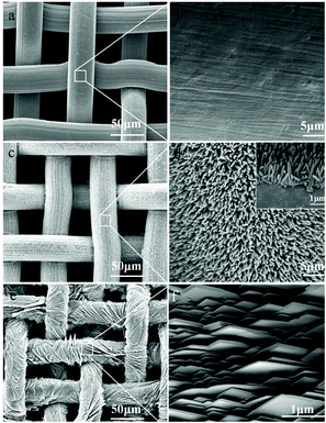 | ||
| Fig. 19 SEM images of the bare stainless steel mesh (SSM) (a and b), ZnO nanorods grown on the SSM (c and d) and oriented Zn2(bIm)4 nanosheet grown on the SSM, SSM-500 (e and f). The inset is the cross section of the ZnO rods grown on the SSM. Reprinted with permission from ref. 82. Copyright 2019 Elsevier. | ||
In another work, Pan and co-workers prepared a high-quality ZIF-8 membrane by means of the partial self-conversion of a sputter-coated ZnO layer on a porous α-alumina support to ZIF-8.174 Compared to coating ZnO particles by the sol–gel method, sputtering deposition of ZnO particles on a substrate was much more controllable. After the hydrothermal treatment of the ZnO coated substrate in an aqueous solution of 2-methylimidazole, a layer of ZIF-8 could be successfully formed due to the partial conversion of sputter coated ZnO to ZIF-8. After a secondary growth of the resulting ZIF-8 layer, a high quality ZIF-8 membrane was obtained, which showed a high propylene/propane separation factor up to 53. The authors also demonstrated that the introduction of ZnO by sputter coating in the membrane fabrication process greatly improved the reproducibility of the ZIF-8 membranes, and the qualities of the ZIF-8 membrane were highly dependent on the amount of the deposited ZnO. Liu et al. reported the preparation of ZIF-8-coated In2O3 nanofibers by using In2O3/ZnO composite fibers.175 The In2O3/ZnO composite fibers were obtained by electrospinning and subsequent calcination. After a solvothermal reaction of the composite fibers and the ligand 2-methylimidazole, the surface of In2O3 nanofibers was uniformly deposited with ZIF-8 nanocrystals, resulting in an In2O3/ZIF-8 core–shell structure. During the process, the ZnO particles were all converted to ZIF-8 crystals. The authors also demonstrated that the resulting In2O3/ZIF-8 nanofibers acted as an efficient sensing material for the detection of ppb-level NO2.
In a different way, Kitagawa and co-workers prepared a hierarchically porous architecture consisting of microporous MOF crystals by the morphological replacement of metal oxide (Al2O3) used both as a metal source and as an architecture-directing agent by the Al(III)-based MOF [Al(OH)(ndc)]n (H2ndc = 1,4-naphthalenedicarboxylic acid).176 The 2D honeycomb structure of Al2O3 was prepared by a sol–gel process with polystyrene beads as hard templates. The SEM image showed that the Al2O3 honeycomb structure was composed of well-ordered macroscopic hexagonal pores and Al2O3 walls with a thickness of 50 nm (Fig. 20d). The Al2O3 honeycomb structure was then subjected to a reaction of 180 °C in an aqueous solution of the free ligand H2ndc. After the reaction, the Al2O3 walls were all converted into the intergrown MOF crystals of [Al(OH)(ndc)]n in sizes of 10–200 nm (Fig. 20e). Interestingly, the 2D honeycomb architecture structure of Al2O3 was retained in the resulting hierarchical structure of the MOF. Similarly, 3D opal Al2O3 architecture could also be converted into a 3D opal architecture of [Al(OH)(ndc)]n (Fig. 20e, f and g). A dissolution–reprecipitation mechanism was proposed for the conversion, in which the metastable parent Al2O3 dissolved in the fluid at the solid/liquid interface and at the same time a new stable daughter phase (the MOF [Al(OH)(ndc)]n) was crystalized at the same site. The honeycomb MOF structure was hierarchically porous and used for the separation of a mixed system of water and ethanol. The results suggested that the hydrophobic and hierarchically porous nature of the honeycomb MOF structure synergistically enhanced the material's selectivity and mass transfer for water/ethanol separation.
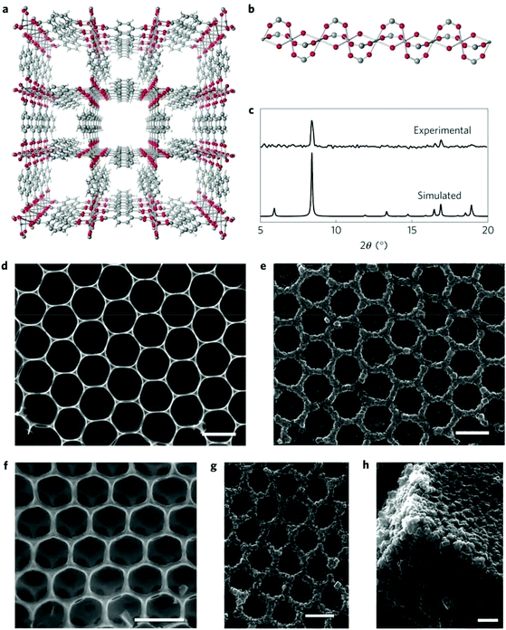 | ||
| Fig. 20 (a) The crystal structure of [Al(OH)(ndc)]n. (b) A chain composed of corner-sharing octahedral Al(OH)2O4 units in the structure of [Al(OH)(ndc)]n. (c) Synchrotron X-ray diffraction pattern of the honeycomb architecture and the simulated pattern of [Al(OH)(ndc)]n. (d) Top-view SEM image of the 2D Al2O3 honeycomb architecture. (e) Top-view SEM image of the 2D honeycomb architecture of [Al(OH)(ndc)]n. (f) Top-view SEM image of the 3D Al2O3 opal architecture. (g and h) SEM images of the 3D opal architecture of [Al(OH)(ndc)]n (top and side views, respectively). All scale bars, 1 μm. Reprinted with permission from ref. 176. Copyright 2012 Springer Nature. | ||
3. Conclusion
The reported methods for the shaping of MOFs bring great promise to the industrial application of MOF-based materials. In particular, the late advancement in templated shaping, self-shaping, shaping by in situ growth on substrates, and shaping with sacrificial materials offers encouraging results for the application realization of shaped MOFs. However, it should be noted that each MOF shaping method has its own advantages and limitations, and the optimum method for shaping a MOF-base material is highly dependent on the specific application it will be applied to. The mechanical shaping method is easy and highly feasible, but the resulting products sometimes are affected by the binder, wetting agent, or high pressure, resulting in compromised porosity and adsorption capacity. The shaping methods using a substrate for the in situ growth of supported MOF crystals are promising in fabricating many useful materials such as an air filter, membrane, and sensor, while a suitable substrate or a pre-modification of the substrate is needed, prolonging the shaping time and increasing the cost. Self-shaping of MOFs is an intriguing technique because no binder, additive, or substrate is needed to produce a MOF monolith with high mechanical stability, high density and volumetric adsorption capacity, although the experimental process seems tricky and the synthesis of nano-sized MOF crystals is necessary. Anyway, many important methods for shaping MOFs have been developed, which could be further explored and optimized for the specific application of these types of porous materials. As an extension of the design and synthesis, the shaping technology of MOF materials would advance and promote the future practical application of MOF-based materials. The future challenges of MOF shaping include (1) overcoming the negative effect of shaping on the adsorption kinetics of MOFs, (2) avoiding the leaking of fine MOF particles from shaped products in long-term use, and (3) identifying optimum shaping methods for specific applications. These issues were overlooked in most existing works, suggesting the efforts that future studies should make.Conflicts of interest
There are no conflicts of interest to declare.Acknowledgements
The authors would like to acknowledge financial support from the National Key R&D Program of China (Grant No. 2018YFC1903303), the Natural Science Foundation of China (Grant No. 21601008), and the Beijing Natural Science Foundation (Grant No. 2182005).References
- Q. Xu and H. Kitagawa, MOFs: New Useful Materials – A Special Issue in Honor of Prof. Susumu Kitagawa, Adv. Mater., 2018, 30, 1803613 CrossRef PubMed.
- G. Maurin, C. Serre, A. Cooper and G. Férey, The new age of MOFs and of their porous-related solids, Chem. Soc. Rev., 2017, 46, 3104–3107 RSC.
- H.-C. Zhou and S. Kitagawa, Metal-Organic Frameworks (MOFs), Chem. Soc. Rev., 2014, 43, 5415–5418 RSC.
- H.-C. Zhou, J. R. Long and O. M. Yaghi, Introduction to Metal–Organic Frameworks, Chem. Rev., 2012, 112, 673–674 CrossRef CAS PubMed.
- H. Furukawa, K. E. Cordova, M. O'Keeffe and O. M. Yaghi, The Chemistry and Applications of Metal-Organic Frameworks, Science, 2013, 341, 974 CrossRef CAS PubMed.
- J. R. Long and O. M. Yaghi, The pervasive chemistry of metal-organic frameworks, Chem. Soc. Rev., 2009, 38, 1213–1214 RSC.
- R. B. Getman, Y.-S. Bae, C. E. Wilmer and R. Q. Snurr, Review and Analysis of Molecular Simulations of Methane, Hydrogen, and Acetylene Storage in Metal–Organic Frameworks, Chem. Rev., 2012, 112, 703–723 CrossRef CAS PubMed.
- M. P. Suh, H. J. Park, T. K. Prasad and D. W. Lim, Hydrogen Storage in Metal-Organic Frameworks, Chem. Rev., 2012, 112, 782–835 CrossRef CAS PubMed.
- Y. He, W. Zhou, G. Qian and B. Chen, Methane storage in metal-organic frameworks, Chem. Soc. Rev., 2014, 43, 5657–5678 RSC.
- L. J. Murray, M. Dinca and J. R. Long, Hydrogen storage in metal-organic frameworks, Chem. Soc. Rev., 2009, 38, 1294–1314 RSC.
- R. E. Morris and P. S. Wheatley, Gas storage in nanoporous materials, Angew. Chem., Int. Ed., 2008, 47, 4966–4981 CrossRef CAS PubMed.
- X. Zhao, Y. Wang, D.-S. Li, X. Bu and P. Feng, Metal–Organic Frameworks for Separation, Adv. Mater., 2018, 30, 1705189 CrossRef PubMed.
- K. Adil, Y. Belmabkhout, R. S. Pillai, A. Cadiau, P. M. Bhatt, A. H. Assen, G. Maurin and M. Eddaoudi, Gas/vapour separation using ultra-microporous metal–organic frameworks: insights into the structure/separation relationship, Chem. Soc. Rev., 2017, 46, 3402–3430 RSC.
- J.-R. Li, R. J. Kuppler and H.-C. Zhou, Selective gas adsorption and separation in metal-organic frameworks, Chem. Soc. Rev., 2009, 38, 1477–1504 RSC.
- J. B. DeCoste and G. W. Peterson, Metal–Organic Frameworks for Air Purification of Toxic Chemicals, Chem. Rev., 2014, 114, 5695–5727 CrossRef CAS PubMed.
- E. Barea, C. Montoro and J. A. R. Navarro, Toxic gas removal – metal–organic frameworks for the capture and degradation of toxic gases and vapours, Chem. Soc. Rev., 2014, 43, 5419–5430 RSC.
- P.-Q. Liao, N.-Y. Huang, W.-X. Zhang, J.-P. Zhang and X.-M. Chen, Controlling guest conformation for efficient purification of butadiene, Science, 2017, 356, 1193–1196 CrossRef CAS PubMed.
- L. Jiao, Y. Wang, H.-L. Jiang and Q. Xu, Metal–Organic Frameworks as Platforms for Catalytic Applications, Adv. Mater., 2018, 30, 1703663 CrossRef PubMed.
- S. M. J. Rogge, A. Bavykina, J. Hajek, H. Garcia, A. I. Olivos-Suarez, A. Sepúlveda-Escribano, A. Vimont, G. Clet, P. Bazin, F. Kapteijn, M. Daturi, E. V. Ramos-Fernandez, F. X. Llabrés i Xamena, V. Van Speybroeck and J. Gascon, Metal–organic and covalent organic frameworks as single-site catalysts, Chem. Soc. Rev., 2017, 46, 3134–3184 RSC.
- M. Yoon, R. Srirambalaji and K. Kim, Homochiral Metal–Organic Frameworks for Asymmetric Heterogeneous Catalysis, Chem. Rev., 2012, 112, 1196–1231 CrossRef CAS PubMed.
- A. Dhakshinamoorthy, A. M. Asiri and H. García, Metal–Organic Framework (MOF) Compounds: Photocatalysts for Redox Reactions and Solar Fuel Production, Angew. Chem., Int. Ed., 2016, 55, 5414–5445 CrossRef CAS PubMed.
- M. Zhao, K. Yuan, Y. Wang, G. Li, J. Guo, L. Gu, W. Hu, H. Zhao and Z. Tang, Metal–organic frameworks as selectivity regulators for hydrogenation reactions, Nature, 2016, 539, 76–80 CrossRef CAS PubMed.
- W. P. Lustig, S. Mukherjee, N. D. Rudd, A. V. Desai, J. Li and S. K. Ghosh, Metal–organic frameworks: functional luminescent and photonic materials for sensing applications, Chem. Soc. Rev., 2017, 46, 3242–3285 RSC.
- I. Stassen, N. Burtch, A. Talin, P. Falcaro, M. Allendorf and R. Ameloot, An updated roadmap for the integration of metal–organic frameworks with electronic devices and chemical sensors, Chem. Soc. Rev., 2017, 46, 3185–3241 RSC.
- M. Woellner, S. Hausdorf, N. Klein, P. Mueller, M. W. Smith and S. Kaskel, Adsorption and Detection of Hazardous Trace Gases by Metal–Organic Frameworks, Adv. Mater., 2018, 30, 1704679 CrossRef PubMed.
- H. Wang, W. P. Lustig and J. Li, Sensing and capture of toxic and hazardous gases and vapors by metal–organic frameworks, Chem. Soc. Rev., 2018, 47, 4729–4756 RSC.
- B. Yan, Lanthanide-functionalized metal–organic framework hybrid systems to create multiple luminescent centers for chemical sensing, Acc. Chem. Res., 2017, 50, 2789–2798 CrossRef CAS PubMed.
- L. Li, R.-B. Lin, R. Krishna, H. Li, S. Xiang, H. Wu, J. Li, W. Zhou and B. Chen, Ethane/ethylene separation in a metal-organic framework with iron-peroxo sites, Science, 2018, 362, 443 CrossRef CAS PubMed.
- A. Cadiau, K. Adil, P. M. Bhatt, Y. Belmabkhout and M. Eddaoudi, A metal-organic framework-based splitter for separating propylene from propane, Science, 2016, 353, 137–140 CrossRef CAS PubMed.
- P. Nugent, Y. Belmabkhout, S. D. Burd, A. J. Cairns, R. Luebke, K. Forrest, T. Pham, S. Q. Ma, B. Space, L. Wojtas, M. Eddaoudi and M. J. Zaworotko, Porous materials with optimal adsorption thermodynamics and kinetics for CO2 separation, Nature, 2013, 495, 80–84 CrossRef CAS PubMed.
- C.-T. He, L. Jiang, Z.-M. Ye, R. Krishna, Z.-S. Zhong, P.-Q. Liao, J. Xu, G. Ouyang, J.-P. Zhang and X.-M. Chen, Exceptional hydrophobicity of a large-pore metal-organic zeolite, J. Am. Chem. Soc., 2015, 137, 7217–7223 CrossRef CAS PubMed.
- S. A. A. Razavi and A. Morsali, Linker functionalized metal-organic frameworks, Coord. Chem. Rev., 2019, 399, 213023 CrossRef.
- N.-X. Zhu, Z.-W. Wei, C.-X. Chen, D. Wang, C.-C. Cao, Q.-F. Qiu, J.-J. Jiang, H.-P. Wang and C.-Y. Su, Self-Generation of Surface Roughness by Low-Surface-Energy Alkyl Chains for Highly Stable Superhydrophobic/Superoleophilic MOFs with Multiple Functionalities, Angew. Chem., Int. Ed., 2019, 58, 17033–17040 CrossRef CAS PubMed.
- C. Xu, R. Fang, R. Luque, L. Chen and Y. Li, Functional metal-organic frameworks for catalytic applications, Coord. Chem. Rev., 2019, 388, 268–292 CrossRef CAS.
- S. M. Cohen, Postsynthetic Methods for the Functionalization of Metal–Organic Frameworks, Chem. Rev., 2012, 112, 970–1000 CrossRef CAS PubMed.
- Q. Sun, H. He, W.-Y. Gao, B. Aguila, L. Wojtas, Z. Dai, J. Li, Y.-S. Chen, F.-S. Xiao and S. Ma, Imparting amphiphobicity on single-crystalline porous materials, Nat. Commun., 2016, 7, 13300 CrossRef CAS PubMed.
- Z. Zhang and M. J. Zaworotko, Template-directed synthesis of metal-organic materials, Chem. Soc. Rev., 2014, 43, 5444–5455 RSC.
- J.-P. Zhang, Y.-B. Zhang, J.-B. Lin and X.-M. Chen, Metal azolate frameworks: From crystal engineering to functional materials, Chem. Rev., 2012, 112, 1001–1033 CrossRef CAS PubMed.
- M. Li, D. Li, M. O'Keeffe and O. M. Yaghi, Topological Analysis of Metal–Organic Frameworks with Polytopic Linkers and/or Multiple Building Units and the Minimal Transitivity Principle, Chem. Rev., 2014, 114, 1343–1370 CrossRef CAS PubMed.
- N. Stock and S. Biswas, Synthesis of metal-organic frameworks (mofs): routes to various mof topologies, morphologies, and composites, Chem. Rev., 2012, 112, 933–969 CrossRef CAS PubMed.
- X.-L. Luo, Z. Yin, M.-H. Zeng and M. Kurmoo, The construction, structures, and functions of pillared layer metal–organic frameworks, Inorg. Chem. Front., 2016, 3, 1208–1226 RSC.
- J.-H. Wang, Y. Zhang, M. Li, S. Yan, D. Li and X.-M. Zhang, Solvent-Assisted Metal Metathesis: A Highly Efficient and Versatile Route towards Synthetically Demanding Chromium Metal–Organic Frameworks, Angew. Chem., Int. Ed., 2017, 56, 6478–6482 CrossRef CAS PubMed.
- M. Rubio-Martinez, C. Avci-Camur, A. W. Thornton, I. Imaz, D. Maspoch and M. R. Hill, New synthetic routes towards MOF production at scale, Chem. Soc. Rev., 2017, 46, 3453–3480 RSC.
- N. C. Burtch, H. Jasuja and K. S. Walton, Water stability and adsorption in metal–organic frameworks, Chem. Rev., 2014, 114, 10575–10612 CrossRef CAS PubMed.
- M. F. de Lange, K. J. F. M. Verouden, T. J. H. Vlugt, J. Gascon and F. Kapteijn, Adsorption-Driven Heat Pumps: The Potential of Metal–Organic Frameworks, Chem. Rev., 2015, 115, 12205–12250 CrossRef CAS PubMed.
- N. S. Bobbitt, M. L. Mendonca, A. J. Howarth, T. Islamoglu, J. T. Hupp, O. K. Farha and R. Q. Snurr, Metal–organic frameworks for the removal of toxic industrial chemicals and chemical warfare agents, Chem. Soc. Rev., 2017, 46, 3357–3385 RSC.
- W.-Y. Gao, Y. Chen, Y. Niu, K. Williams, L. Cash, P. J. Perez, L. Wojtas, J. Cai, Y.-S. Chen and S. Ma, Crystal Engineering of an nbo Topology Metal-Organic Framework for Chemical Fixation of CO2 under Ambient Conditions, Angew. Chem., Int. Ed., 2014, 53, 2615–2619 CrossRef CAS PubMed.
- Z.-S. Wang, M. Li, Y.-L. Peng, Z. Zhang, W. Chen and X.-C. Huang, An Ultrastable Metal Azolate Framework with Binding Pockets for Optimal Carbon Dioxide Capture, Angew. Chem., Int. Ed., 2019, 58, 16071–16076 CrossRef CAS PubMed.
- Editorial, Frameworks for commercial success, Nat. Chem., 2016, 8, 987–987 Search PubMed.
- A. U. Czaja, N. Trukhan and U. Muller, Industrial applications of metal-organic frameworks, Chem. Soc. Rev., 2009, 38, 1284–1293 RSC.
- F. Akhtar, L. Andersson, S. Ogunwumi, N. Hedin and L. Bergstrom, Structuring adsorbents and catalysts by processing of porous powders, J. Eur. Ceram. Soc., 2014, 34, 1643–1666 CrossRef CAS.
- P. Iacomi, U. H. Lee, A. H. Valekar, J.-S. Chang and P. L. Llewellyn, Investigating the effect of alumina shaping on the sorption properties of promising metal-organic frameworks, RSC Adv., 2019, 9, 7128–7135 RSC.
- J. Ren, N. M. Musyoka, H. W. Langmi, A. Swartbooi, B. C. North and M. Mathe, A more efficient way to shape metal-organic framework (MOF) powder materials for hydrogen storage applications, Int. J. Hydrogen Energy, 2015, 40, 4617–4622 CrossRef CAS.
- A. H. Valekar, K.-H. Cho, U. H. Lee, J. S. Lee, J. W. Yoon, Y. K. Hwang, S. G. Lee, S. J. Cho and J.-S. Chang, Shaping of porous metal-organic framework granules using mesoporous rho-alumina as a binder, RSC Adv., 2017, 7, 55767–55777 RSC.
- M. Kriesten, J. V. Schmitz, J. Siegel, C. E. Smith, M. Kaspereit and M. Hartmann, Shaping of Flexible Metal-Organic Frameworks: Combining Macroscopic Stability and Framework Flexibility, Eur. J. Inorg. Chem., 2019, 4700–4709 CrossRef CAS.
- B. Mortada, G. Chaplais, H. Nouali, C. Marichal and J. Patarin, Phase Transformations of Metal-Organic Frameworks MAF-6 and ZIF-71 during Intrusion-Extrusion Experiments, J. Phys. Chem. C, 2019, 123, 4319–4328 CrossRef CAS.
- J. J. Richardson, B. L. Tardy, J. Guo, K. Liang, O. J. Rojas and H. Ejima, Continuous Metal-Organic Framework Biomineralization on Cellulose Nanocrystals: Extrusion of Functional Composite Filaments, ACS Sustainable Chem. Eng., 2019, 7, 6287–6294 CrossRef CAS.
- C. Avci-Camur, J. Troyano, J. Perez-Carvajal, A. Legrand, D. Farrusseng, I. Imaz and D. Maspoch, Aqueous production of spherical Zr-MOF beads via continuous-flow spray-drying, Green Chem., 2018, 20, 873–878 RSC.
- S. Chaemchuen, K. Zhou, B. Mousavi, M. Ghadamyari, P. M. Heynderickx, S. Zhuiykov, M. S. Yusubov and F. Verpoort, Spray drying of zeolitic imidazolate frameworks: investigation of crystal formation and properties, CrystEngComm, 2018, 20, 3601–3608 RSC.
- J. Sun, H. T. Kwon and H.-K. Jeong, Continuous synthesis of high quality metal-organic framework HKUST-1 crystals and composites via aerosol-assisted synthesis, Polyhedron, 2018, 153, 226–233 CrossRef CAS.
- G. Li, K. Zhang, C. Li, R. Gao, Y. Cheng, L. Hou and Y. Wang, Solvent-free method to encapsulate polyoxometalate into metal-organic frameworks as efficient and recyclable photocatalyst for harmful sulfamethazine degrading in water, Appl. Catal., B, 2019, 245, 753–759 CrossRef CAS.
- X. Ma, Y. Chai, P. Li and B. Wang, Metal-Organic Framework Films and Their Potential Applications in Environmental Pollution Control, Acc. Chem. Res., 2019, 52, 1461–1470 CAS.
- Y.-J. Tang, H.-J. Zhu, L.-Z. Dong, A. M. Zhang, S.-L. Li, J. Liu and Y.-Q. Lan, Solid-phase hot-pressing of POMs-ZIFs precursor and derived phosphide for overall water splitting, Appl. Catal., B, 2019, 245, 528–535 CrossRef CAS.
- Y. Hara, K. Kanamori and K. Nakanishi, Self-Assembly of Metal-Organic Frameworks into Monolithic Materials with Highly Controlled Trimodal Pore Structures, Angew. Chem., Int. Ed., 2019, 58, 19047–19053 CrossRef CAS PubMed.
- J. Kong, F. Zhu, W. Huang, H. He, J. Hui, C. Sun, Q. Xian and S. Yang, Sol-gel based metal-organic framework zeolite imidazolate framework-8 fibers for solid-phase microextraction of nitro polycyclic aromatic hydrocarbons and polycyclic aromatic hydrocarbons in water samples, J. Chromatogr. A, 2019, 1603, 92–101 CrossRef CAS PubMed.
- Q. Liu, Q. Zhang, B. Liu and J. Ma, A new synthesis and adsorption mechanism of ZrO2 based metal-organic frames for efficient removal of mercury ions from aqueous solution, Ceram. Int., 2019, 45, 15720–15724 CrossRef CAS.
- S. Han, R. A. Ciufo, M. L. Meyerson, B. K. Keitz and C. B. Mullins, Solvent-free vacuum growth of oriented HKUST-1 thin films, J. Mater. Chem. A, 2019, 7, 19396–19406 RSC.
- A. P. Kutenina, A. I. Zvyagina, O. A. Raitman, Y. Y. Enakieva and M. A. Kalinina, Layer-by-Layer Assembly of SAM-supported Porphyrin-based Metal Organic Frameworks for Molecular Recognition, Colloid J., 2019, 81, 401–410 CrossRef CAS.
- J. Liu, F. Yang, Q. Zhang, W. Chen, Y. Gu and Q. Chen, Construction of Hierarchical Fe3O4@HKUST-1/MIL-100(Fe) Microparticles with Large Surface Area through Layer-by-Layer Deposition and Epitaxial Growth Methods, Inorg. Chem., 2019, 58, 3564–3568 CrossRef CAS PubMed.
- S. Aguado, J. Canivet and D. Farrusseng, Engineering structured MOF at nano and macroscales for catalysis and separation, J. Mater. Chem., 2011, 21, 7582–7588 RSC.
- G.-P. Hao, W.-C. Li, D. Qian, G.-H. Wang, W.-P. Zhang, T. Zhang, A.-Q. Wang, F. Schueth, H.-J. Bongard and A.-H. Lu, Structurally Designed Synthesis of Mechanically Stable Poly(benzoxazine-co-resol)-Based Porous Carbon Monoliths and Their Application as High-Performance CO2 Capture Sorbents, J. Am. Chem. Soc., 2011, 133, 11378–11388 CrossRef CAS PubMed.
- R. Bingre, B. Louis and P. Nguyen, An Overview on Zeolite Shaping Technology and Solutions to Overcome Diffusion Limitations, Catalysts, 2018, 8, 163 CrossRef CAS.
- J. Yu, L.-H. Xie, J.-R. Li, Y. Ma, J. M. Seminario and P. B. Balbuena, CO2 Capture and Separations Using MOFs: Computational and Experimental Studies, Chem. Rev., 2017, 117, 9674–9754 CrossRef CAS PubMed.
- B. S. Gelfand and G. K. Shimizu, Parameterizing and grading hydrolytic stability in metal–organic frameworks, Dalton Trans., 2016, 45, 3668–3678 RSC.
- A. J. Howarth, Y. Liu, P. Li, Z. Li, T. C. Wang, J. T. Hupp and O. K. Farha, Chemical, thermal and mechanical stabilities of metal–organic frameworks, Nat. Rev. Mater., 2016, 1, 15018 CrossRef CAS.
- W. Gu, J. Lv, B. Quan, X. Liang, B. Zhang and G. Ji, Achieving MOF-derived one-dimensional porous ZnO/C nanofiber with lightweight and enhanced microwave response by an electrospinning method, J. Alloys Compd., 2019, 806, 983–991 CrossRef CAS.
- L. Jin, J. Ye, Y. Wang, X. Qian and M. Dong, Electrospinning Synthesis of ZIF-67/PAN Fibrous Membrane with High-capacity Adsorption for Malachite Green, Fibers Polym., 2019, 20, 2070–2077 CrossRef CAS.
- M. Liu, N. Cai, V. Chan and F. Yu, Development and Applications of MOFs Derivative One-Dimensional Nanofibers via Electrospinning: A Mini-Review, Nanomaterials, 2019, 9, 1306 CrossRef CAS PubMed.
- J. Troyano, A. Carne-Sanchez and D. Maspoch, Programmable Self-Assembling 3D Architectures Generated by Patterning of Swellable MOF-Based Composite Films, Adv. Mater., 2019, 31, 1808235 CrossRef PubMed.
- T. Tsuruoka, M. Hata, S. Hirao, T. Ohhashi, Y. Takashima and K. Akamatsu, Formation of Metal-Organic Frameworks on a Metal Ion-Doped Polymer Substrate: In-Depth Time-Course Analysis Using Scanning Electron Microscopy, Langmuir, 2019, 35, 10390–10396 CrossRef CAS PubMed.
- Y. Li, L. Lin, M. Tu, P. Nian, A. J. Howarth, O. K. Farha, J. Qiu and X. Zhang, Growth of ZnO self-converted 2D nanosheet zeolitic imidazolate framework membranes by an ammonia-assisted strategy, Nano Res., 2018, 11, 1850–1860 CrossRef CAS.
- C. Ma, Y. Li, P. Nian, H. Liu, J. Qiu and X. Zhang, Fabrication of oriented metal-organic framework nanosheet membrane coated stainless steel meshes for highly efficient oil/water separation, Sep. Purif. Technol., 2019, 229, 115835 CrossRef CAS.
- B. Valizadeh, T. N. Nguyen and K. C. Stylianou, Shape engineering of metal-organic frameworks, Polyhedron, 2018, 145, 1–15 CrossRef CAS.
- X. C. Huang, Y. Y. Lin, J. P. Zhang and X. M. Chen, Ligand-directed strategy for zeolite-type metal-organic frameworks: Zinc(II) imidazolates with unusual zeolitic topologies, Angew. Chem., Int. Ed., 2006, 45, 1557–1559 CrossRef CAS PubMed.
- K. S. Park, Z. Ni, A. P. Cote, J. Y. Choi, R. D. Huang, F. J. Uribe-Romo, H. K. Chae, M. O'Keeffe and O. M. Yaghi, Exceptional chemical and thermal stability of zeolitic imidazolate frameworks, Proc. Natl. Acad. Sci. U. S. A., 2006, 103, 10186–10191 CrossRef CAS PubMed.
- H. Li, M. Eddaoudi, M. O'Keeffe and O. M. Yaghi, Design and synthesis of an exceptionally stable and highly porous metal-organic framework, Nature, 1999, 402, 276–279 CrossRef CAS.
- M. Eddaoudi, J. Kim, N. Rosi, D. Vodak, J. Wachter, M. O'Keefe and O. M. Yaghi, Systematic design of pore size and functionality in isoreticular MOFs and their application in methane storage, Science, 2002, 295, 469–472 CrossRef CAS PubMed.
- G. Ferey, C. Mellot-Draznieks, C. Serre, F. Millange, J. Dutour, S. Surble and I. Margiolaki, A chromium terephthalate-based solid with unusually large pore volumes and surface area, Science, 2005, 309, 2040–2042 CrossRef CAS PubMed.
- H. K. Chae, D. Y. Siberio-Perez, J. Kim, Y. Go, M. Eddaoudi, A. J. Matzger, M. O'Keeffe and O. M. Yaghi, A route to high surface area, porosity and inclusion of large molecules in crystals, Nature, 2004, 427, 523–527 CrossRef CAS PubMed.
- J. Cavka, S. Jakobsen, U. Olsbye, N. Guillou, C. Lamberti, S. Bordiga and K. Lillerud, A new zirconium inorganic building brick forming metal organic frameworks with exceptional stability, J. Am. Chem. Soc., 2008, 130, 13850–13851 CrossRef PubMed.
- C. Serre, F. Millange, C. Thouvenot, M. Nogues, G. Marsolier, D. Louer and G. Ferey, Very large breathing effect in the first nanoporous chromium(III)-based solids: MIL-53 or CrIII(OH)·{O2C-C6H4-CO2}·{HO2C-C6H4-CO2H}x·H2Oy, J. Am. Chem. Soc., 2002, 124, 13519–13526 CrossRef CAS PubMed.
- T. Loiseau, C. Serre, C. Huguenard, G. Fink, F. Taulelle, M. Henry, T. Bataille and G. Ferey, A rationale for the large breathing of the porous aluminum terephthalate (MIL-53) upon hydration, Chem. – Eur. J., 2004, 10, 1373–1382 CrossRef CAS PubMed.
- F. Millange, N. Guillou, R. I. Walton, J.-M. Grenèche, I. Margiolaki and G. Férey, Effect of the nature of the metal on the breathing steps in MOFs with dynamic frameworks, Chem. Commun., 2008, 4732–4734 RSC.
- S. S. Y. Chui, S. M. F. Lo, J. P. H. Charmant, A. G. Orpen and I. D. Williams, A chemically functionalizable nanoporous material [Cu3(TMA)2(H2O)3]n, Science, 1999, 283, 1148–1150 CrossRef CAS PubMed.
- D. Bazer-Bachi, L. Assie, V. Lecocq, B. Harbuzaru and V. Falk, Towards industrial use of metal-organic framework: Impact of shaping on the MOF properties, Powder Technol., 2014, 255, 52–59 CrossRef CAS.
- U. H. Lee, A. H. Valekar, Y. K. Hwang and J. S. Chang, in Chapter 18. Granulation and Shaping of Metal–Organic Frameworks, The Chemistry of Metal–Organic Frameworks: The Chemistry of Metal–Organic Frameworks: Synthesis, Characterization, and Applications, ed. S. Kaskel, Wiley, 2016, vol. 1, pp. 551–572 Search PubMed.
- B. B. Shah, T. Kundu and D. Zhao, Mechanical Properties of Shaped Metal-Organic Frameworks, Top. Curr. Chem., 2019, 377, 25 CrossRef PubMed.
- J. Hou, A. F. Sapnik and T. D. Bennett, Metal–organic framework gels and monoliths, Chem. Sci., 2020, 11, 310–323 RSC.
- F. Lorignon, A. Gossard and M. Carboni, Hierarchically porous monolithic MOFs: An ongoing challenge for industrial-scale effluent treatment, Chem. Eng. J., 2020, 393, 124765 CrossRef CAS.
- S. Ohsaki, Y. Nakahara, H. Nakamura and S. Watano, Flowability improvement of soft metal-organic framework particles by wet granulation, Microporous Mesoporous Mater., 2020, 293, 109785 CrossRef CAS.
- A. Mallick, G. Mouchaham, P. M. Bhatt, W. Liang, Y. Belmabkhout, K. Adil, A. Jamal and M. Eddaoudi, Advances in Shaping of Metal–Organic Frameworks for CO2 Capture: Understanding the Effect of Rubbery and Glassy Polymeric Binders, Ind. Eng. Chem. Res., 2018, 57, 16897–16902 CrossRef CAS.
- P.-J. Kim, Y.-W. You, H. Park, J.-S. Chang, Y.-S. Bae, C.-H. Lee and J.-K. Suh, Separation of SF6 from SF6/N2 mixture using metal-organic framework MIL-100(Fe) granule, Chem. Eng. J., 2015, 262, 683–690 CrossRef CAS.
- J. Cousin-Saint-Remi, S. Van der Perre, T. Segato, M.-P. Delplancke, S. Goderis, H. Terryn, G. Baron and J. Denayer, Highly Robust MOF Polymeric Beads with a Controllable Size for Molecular Separations, ACS Appl. Mater. Interfaces, 2019, 11, 13694–13703 CrossRef CAS PubMed.
- D. W. Lee, T. Didriksen, U. Olsbye, R. Blom and C. A. Grande, Shaping of metal-organic framework UiO-66 using alginates: Effect of operation variables, Sep. Purif. Technol., 2020, 235, 116182 CrossRef CAS.
- A. I. Spjelkavik, Aarti, S. Divekar, T. Didriksen and R. Blom, Forming MOFs into Spheres by Use of Molecular Gastronomy Methods, Chem. – Eur. J., 2014, 20, 8973–8978 CAS.
- Y. Khabzina, J. Dhainaut, M. Ahlhelm, H.-J. Richter, H. Reinsch, N. Stock and D. Farrusseng, Synthesis and Shaping Scale-up Study of Functionalized UiO-66 MOF for Ammonia Air Purification Filters, Ind. Eng. Chem. Res., 2018, 57, 8200–8208 CrossRef CAS.
- D. Crawford, J. Casaban, R. Haydon, N. Giri, T. McNally and S. L. James, Synthesis by extrusion: continuous, large-scale preparation of MOFs using little or no solvent, Chem. Sci., 2015, 6, 1645–1649 RSC.
- E. Hastürk, S.-P. Höfert, B. Topalli, C. Schlüsener and C. Janiak, Shaping of MOFs via freeze-casting method with hydrophilic polymers and their effect on textural properties, Microporous Mesoporous Mater., 2020, 295, 109907 CrossRef.
- M. M. Sadiq, M. Rubio-Martinez, F. Zadehahmadi, K. Suzuki and M. R. Hill, Magnetic Framework Composites for Low Concentration Methane Capture, Ind. Eng. Chem. Res., 2018, 57, 6040–6047 CrossRef CAS.
- C. A. Grande, V. I. Agueda, A. Spjelkavik and R. Blom, An efficient recipe for formulation of metal-organic Frameworks, Chem. Eng. Sci., 2015, 124, 154–158 CrossRef CAS.
- F. Figueira, R. E. Mendes, E. M. Domingues, P. Barbosa, F. Figueiredo, F. A. A. Paz and J. Rocha, Easy Processing of Metal-Organic Frameworks into Pellets and Membranes, Appl. Sci., 2020, 10, 798 CrossRef.
- H. Thakkar, S. Eastman, Q. Al-Naddaf, A. A. Rownaghi and F. Rezaei, 3D-Printed Metal–Organic Framework Monoliths for Gas Adsorption Processes, ACS Appl. Mater. Interfaces, 2017, 9, 35908–35916 CrossRef CAS PubMed.
- M. C. Kreider, M. Sefa, J. A. Fedchak, J. Scherschligt, M. Bible, B. Natarajan, N. N. Klimov, A. E. Miller, Z. Ahmed and M. R. Hartings, Toward 3D printed hydrogen storage materials made with ABS-MOF composites, Polym. Adv. Technol., 2018, 29, 867–873 CrossRef CAS PubMed.
- O. Halevi, J. M. R. Tan, P. S. Lee and S. Magdassi, Hydrolytically Stable MOF in 3D-Printed Structures, Adv. Sustainable Syst., 2018, 2, 1700150 CrossRef.
- A. J. Young, R. Guillet-Nicolas, E. S. Marshall, F. Kleitz, A. J. Goodhand, L. B. L. Glanville, M. R. Reithofer and J. M. Chin, Direct ink writing of catalytically active UiO-66 polymer composites, Chem. Commun., 2019, 55, 2190–2193 RSC.
- J. Dhainaut, M. Bonneau, R. Ueoka, K. Kanamori and S. Furukawa, Formulation of Metal–Organic Framework Inks for the 3D Printing of Robust Microporous Solids toward High-Pressure Gas Storage and Separation, ACS Appl. Mater. Interfaces, 2020, 12, 10983–10992 CrossRef PubMed.
- A. Carne-Sanchez, I. Imaz, M. Cano-Sarabia and D. Maspoch, A spray-drying strategy for synthesis of nanoscale metal-organic frameworks and their assembly into hollow superstructures, Nat. Chem., 2013, 5, 203–211 CrossRef CAS PubMed.
- C. Boissiere, D. Grosso, A. Chaumonnot, L. Nicole and C. Sanchez, Aerosol Route to Functional Nanostructured Inorganic and Hybrid Porous Materials, Adv. Mater., 2011, 23, 599–623 CrossRef CAS PubMed.
- S. Tanaka and R. Miyashita, Aqueous-System-Enabled Spray-Drying Technique for the Synthesis of Hollow Polycrystalline ZIF-8 MOF Particles, ACS Omega, 2017, 2, 6437–6445 CrossRef CAS PubMed.
- O. Ardelean, G. Blanita, G. Borodi, M. D. Lazar, I. Misan, I. Coldea and D. Lupu, Volumetric hydrogen adsorption capacity of densified MIL-101 monoliths, Int. J. Hydrogen Energy, 2013, 38, 7046–7055 CrossRef CAS.
- M. Tagliabue, C. Rizzo, R. Millini, P. D. C. Dietzel, R. Blom and S. Zanardi, Methane storage on CPO-27-Ni pellets, J. Porous Mater., 2011, 18, 289–296 CrossRef CAS.
- R. P. P. L. Ribeiro, C. L. Antunes, A. U. Garate, A. F. Portela, M. G. Plaza, J. P. B. Mota and I. A. A. C. Esteves, Binderless shaped metal-organic framework particles: Impact on carbon dioxide adsorption, Microporous Mesoporous Mater., 2019, 275, 111–121 CrossRef CAS.
- H. Zhu, X. Yang, E. D. Cranston and S. Zhu, Flexible and Porous Nanocellulose Aerogels with High Loadings of Metal-Organic-Framework Particles for Separations Applications, Adv. Mater., 2016, 28, 7652–7657 CrossRef CAS.
- R. M. Ashour, A. F. Abdel-Magied, Q. Wu, R. T. Olsson and K. Forsberg, Green Synthesis of Metal-Organic Framework Bacterial Cellulose Nanocomposites for Separation Applications, Polymers, 2020, 12, 1104 CrossRef CAS PubMed.
- S. Zhou, V. Apostolopoulou-Kalkavoura, M. V. Tavares da Costa, L. Bergström, M. Strømme and C. Xu, Elastic Aerogels of Cellulose Nanofibers@Metal–Organic Frameworks for Thermal Insulation and Fire Retardancy, Nano-Micro Lett., 2019, 12, 9 CrossRef.
- Z. Li, N. Hori and A. Takemura, Synthesis and characterization of Cu-BTC metal–organic frameworks onto lignocellulosic fibers by layer-by-layer method in aqueous solution, Cellulose, 2020, 27, 1733–1744 CrossRef CAS.
- K. S. Park, Z. Ni, A. P. Cote, J. Y. Choi, R. Huang, F. J. Uribe-Romo, H. K. Chae, M. O'Keeffe and O. M. Yaghi, Exceptional chemical and thermal stability of zeolitic imidazolate frameworks, Proc. Natl. Acad. Sci. U. S. A., 2006, 103, 10186–10191 CrossRef CAS PubMed.
- J. H. Cavka, S. Jakobsen, U. Olsbye, N. Guillou, C. Lamberti, S. Bordiga and K. P. Lillerud, A new zirconium inorganic building brick forming metal organic frameworks with exceptional stability, J. Am. Chem. Soc., 2008, 130, 13850–13851 CrossRef PubMed.
- P. Horcajada, S. Surble, C. Serre, D.-Y. Hong, Y.-K. Seo, J.-S. Chang, J.-M. Greneche, I. Margiolaki and G. Ferey, Synthesis and catalytic properties of MIL-100(Fe), an iron(III) carboxylate with large pores, Chem. Commun., 2007, 2820–2822 RSC.
- M. M. Hamedi, A. Hajian, A. B. Fall, K. Hakansson, M. Salajkova, F. Lundell, L. Wagberg and L. A. Berglund, Highly Conducting, Strong Nanocomposites Based on Nanocellulose-Assisted Aqueous Dispersions of Single-Wall Carbon Nanotubes, ACS Nano, 2014, 8, 2467–2476 CrossRef CAS PubMed.
- X. Ma, Y. Lou, X.-B. Chen, Z. Shi and Y. Xu, Multifunctional flexible composite aerogels constructed through in situ growth of metal-organic framework nanoparticles on bacterial cellulose, Chem. Eng. J., 2019, 356, 227–235 CrossRef CAS.
- Q. Yang, R. Lu, S. Ren, C. Chen, Z. Chen and X. Yang, Three dimensional reduced graphene oxide/ZIF-67 aerogel: Effective removal cationic and anionic dyes from water, Chem. Eng. J., 2018, 348, 202–211 CrossRef CAS.
- Y. Chen, X. Huang, S. Zhang, S. Li, S. Cao, X. Pei, J. Zhou, X. Feng and B. Wang, Shaping of Metal–Organic Frameworks: From Fluid to Shaped Bodies and Robust Foams, J. Am. Chem. Soc., 2016, 138, 10810–10813 CrossRef CAS PubMed.
- M. S. Denny Jr. and S. M. Cohen, In Situ Modification of Metal–Organic Frameworks in Mixed-Matrix Membranes, Angew. Chem., Int. Ed., 2015, 54, 9029–9032 CrossRef PubMed.
- M. Bognitzki, M. Becker, M. Graeser, W. Massa, J. H. Wendorff, A. Schaper, D. Weber, A. Beyer, A. Goelzhaeuser and A. Greiner, Preparation of sub-micrometer copper fibers via electrospinning, Adv. Mater., 2006, 18, 2384–2386 CrossRef CAS.
- A. Wang, H. Singh, T. A. Hatton and G. C. Rutledge, Field-responsive superparamagnetic composite nanofibers by electrospinning, Polymer, 2004, 45, 5505–5514 CrossRef.
- D. Almecija, D. Blond, J. E. Sader, J. N. Coleman and J. J. Boland, Mechanical properties of individual electrospun polymer-nanotube composite nanofibers, Carbon, 2009, 47, 2253–2258 CrossRef CAS.
- M. Rose, B. Boehringer, M. Jolly, R. Fischer and S. Kaskel, MOF Processing by Electrospinning for Functional Textiles, Adv. Eng. Mater., 2011, 13, 356–360 CrossRef CAS.
- W. Hua, T. Zhang, M. Wang, Y. Zhu and X. Wang, Hierarchically structural PAN/UiO-66-(COOH)(2) nanofibrous membranes for effective recovery of Terbium(III) and Europium(III) ions and their photoluminescence performances, Chem. Eng. J., 2019, 370, 729–741 CrossRef CAS.
- Y. Zhang, Y. Zhang, X. Wang, J. Yu and B. Din, Ultrahigh Metal-Organic Framework Loading and Flexible Nanofibrous Membranes for Efficient CO2 Capture with Long-Term, Ultrastable Recyclability, ACS Appl. Mater. Interfaces, 2018, 10, 34802–34810 CrossRef CAS PubMed.
- M. Armstrong, P. Sirous, B. Shan, R. Wang, C. Zhong, J. Liu and B. Mu, Prolonged HKUST-1 functionality under extreme hydrothermal conditions by electrospinning polystyrene fibers as a new coating method, Microporous Mesoporous Mater., 2018, 270, 34–39 CrossRef CAS.
- B. Dahal, T. Mukhiya, G. P. Ojha, A. Muthurasu, S.-H. Chae, T. Kim, D. Kang and H. Y. Kim, In-built fabrication of MOF assimilated B/N co-doped 3D porous carbon nanofiber network as a binder-free electrode for supercapacitors, Electrochim. Acta, 2019, 301, 209–219 CrossRef CAS.
- M. Zhang, M. Li, W. Wu, J. Chen, X. Ma, Z. Zhang and S. Xiang, MOF/PAN nanofiber-derived N-doped porous carbon materials with excellent electrochemical activity for the simultaneous determination of catechol and hydroquinone, New J. Chem., 2019, 43, 3913–3920 RSC.
- Y. Zhang, S. Yuan, X. Feng, H. Li, J. Zhou and B. Wang, Preparation of Nanofibrous Metal–Organic Framework Filters for Efficient Air Pollution Control, J. Am. Chem. Soc., 2016, 138, 5785–5788 CrossRef CAS PubMed.
- T. Tian, J. Velazquez-Garcia, T. D. Bennett and D. Fairen-Jimenez, Mechanically and chemically robust ZIF-8 monoliths with high volumetric adsorption capacity, J. Mater. Chem. A, 2015, 3, 2999–3005 RSC.
- T. Tian, Z. Zeng, D. Vulpe, M. E. Casco, G. Divitini, P. A. Midgley, J. Silvestre-Albero, J.-C. Tan, P. Z. Moghadam and D. Fairen-Jimenez, A sol-gel monolithic metal-organic framework with enhanced methane uptake, Nat. Mater., 2018, 17, 174–179 CrossRef CAS PubMed.
- B. M. Connolly, M. Aragones-Anglada, J. Gandara-Loe, N. A. Danaf, D. C. Lamb, J. P. Mehta, D. Vulpe, S. Wuttke, J. Silvestre-Albero, P. Z. Moghadam, A. E. H. Wheatley and D. Fairen-Jimenez, Tuning porosity in macroscopic monolithic metal-organic frameworks for exceptional natural gas storage, Nat. Commun., 2019, 10, 2345 CrossRef CAS PubMed.
- B. M. Connolly, D. G. Madden, A. E. H. Wheatley and D. Fairen-Jimenez, Shaping the Future of Fuel: Monolithic Metal–Organic Frameworks for High-Density Gas Storage, J. Am. Chem. Soc., 2020, 142, 8541–8549 CrossRef CAS PubMed.
- J. Cravillon, S. Muenzer, S.-J. Lohmeier, A. Feldhoff, K. Huber and M. Wiebcke, Rapid Room-Temperature Synthesis and Characterization of Nanocrystals of a Prototypical Zeolitic Imidazolate Framework, Chem. Mater., 2009, 21, 1410–1412 CrossRef CAS.
- J.-W. Ye, X. Zhou, Y. Wang, R.-K. Huang, H.-L. Zhou, X.-N. Cheng, Y. Ma and J.-P. Zhang, Room-temperature sintered metal-organic framework nanocrystals: A new type of optical ceramics, Sci. China Mater., 2018, 61, 424–428 CrossRef CAS.
- B. Bueken, N. Van Velthoven, T. Willhammar, T. Stassin, I. Stassen, D. A. Keen, G. V. Baron, J. F. M. Denayer, R. Ameloot, S. Bals, D. De Vos and T. D. Bennett, Gel-based morphological design of zirconium metal–organic frameworks, Chem. Sci., 2017, 8, 3939–3948 RSC.
- J. Hou, H. Zhang, G. P. Simon and H. Wang, Polycrystalline Advanced Microporous Framework Membranes for Efficient Separation of Small Molecules and Ions, Adv. Mater., 2019, 1902009 Search PubMed.
- Y. Liu, Y. Ban and W. Yang, Microstructural Engineering and Architectural Design of Metal–Organic Framework Membranes, Adv. Mater., 2017, 29, 1606949 CrossRef PubMed.
- S. Qiu, M. Xue and G. Zhu, Metal-organic framework membranes: from synthesis to separation application, Chem. Soc. Rev., 2014, 43, 6116–6140 RSC.
- Y. Pan, T. Li, G. Lestari and Z. Lai, Effective separation of propylene/propane binary mixtures by ZIF-8 membranes, J. Membr. Sci., 2012, 390–391, 93–98 CrossRef CAS.
- D. Qian, C. Lei, G.-P. Hao, W.-C. Li and A.-H. Lu, Synthesis of Hierarchical Porous Carbon Monoliths with Incorporated Metal-Organic Frameworks for Enhancing Volumetric Based CO2 Capture Capability, ACS Appl. Mater. Interfaces, 2012, 4, 6125–6132 CrossRef CAS.
- M. L. Pinto, S. Dias and J. Pires, Composite MOF Foams: The Example of UiO-66/Polyurethane, ACS Appl. Mater. Interfaces, 2013, 5, 2360–2363 CrossRef CAS PubMed.
- P. Küsgens, S. Siegle and S. Kaskel, Crystal Growth of the Metal-Organic Framework Cu-3(BTC)(2) on the Surface of Pulp Fibers, Adv. Eng. Mater., 2009, 11, 93–95 CrossRef.
- T.-T. Li, L. Liu, M.-L. Gao and Z.-B. Han, A highly stable nanofibrous Eu-MOF membrane as a convenient fluorescent test paper for rapid and cyclic detection of nitrobenzene, Chem. Commun., 2019, 55, 4941–4944 RSC.
- Y. X. Sun, F. Yang, Q. Wei, N. X. Wang, X. Qin, S. K. Zhang, B. Wang, Z. R. Nie, S. L. Ji, H. Yan and J. R. Li, Oriented Nano-Microstructure-Assisted Controllable Fabrication of Metal-Organic Framework Membranes on Nickel Foam, Adv. Mater., 2016, 28, 2374–2381 CrossRef CAS PubMed.
- R. Zhang, S. Ji, N. Wang, L. Wang, G. Zhang and J.-R. Li, Coordination-Driven In Situ Self-Assembly Strategy for the Preparation of Metal-Organic Framework Hybrid Membranes, Angew. Chem., Int. Ed., 2014, 53, 9775–9779 CrossRef CAS PubMed.
- A. Huang, N. Wang, C. Kong and J. Caro, Organosilica-Functionalized Zeolitic Imidazolate Framework ZIF-90 Membrane with High Gas-Separation Performance, Angew. Chem., Int. Ed., 2012, 51, 10551–10555 CrossRef PubMed.
- L. Yin, Z. Liu, Y. Yang, Y. Guo, G. Zhang, F. Gai, Y. Ao, J. Liu, B. Xin and Y. Liu, Structured carbon fiber cloth-templated ZIF-8 by binder-free method for efficient dyes removal from water, Mater. Chem. Phys., 2020, 242, 122563 CrossRef CAS.
- C. Shen, Z. Mao, H. Xu, L. Zhang, Y. Zhong, B. Wang, X. Feng, C.-A. Tao and X. Sui, Catalytic MOF-loaded cellulose sponge for rapid degradation of chemical warfare agents simulant, Carbohydr. Polym., 2019, 213, 184–191 CrossRef CAS PubMed.
- Y. Xie, C. A. S. Hill, Z. Xiao, H. Militz and C. Mai, Silane coupling agents used for natural fiber/polymer composites: A review, Composites, Part A, 2010, 41, 806–819 CrossRef.
- Q. Yang, M. Zhang, S. Song and B. Yang, Surface modification of PCC filled cellulose paper by MOF-5 (Zn-3(BDC)(2)) metal-organic frameworks for use as soft gas adsorption composite materials, Cellulose, 2017, 24, 3051–3060 CrossRef CAS.
- D. Wisser, F. M. Wisser, S. Raschke, N. Klein, M. Leistner, J. Grothe, E. Brunner and S. Kaskel, Biological Chitin-MOF Composites with Hierarchical Pore Systems for Air-Filtration Applications, Angew. Chem., Int. Ed., 2015, 54, 12588–12591 CrossRef CAS PubMed.
- M. Matsumoto and T. Kitaoka, Ultraselective Gas Separation by Nanoporous Metal-Organic Frameworks Embedded in Gas-Barrier Nanocellulose Films, Adv. Mater., 2016, 28, 1765–1769 CrossRef CAS PubMed.
- T. Saito, S. Kimura, Y. Nishiyama and A. Isogai, Cellulose nanofibers prepared by TEMPO-mediated oxidation of native cellulose, Biomacromolecules, 2007, 8, 2485–2491 CrossRef CAS PubMed.
- T. Saito and A. Isogai, Ion-exchange behavior of carboxylate groups in fibrous cellulose oxidized by the TEMPO-mediated system, Carbohydr. Polym., 2005, 61, 183–190 CrossRef CAS.
- J. Zhao, M. D. Losego, P. C. Lemaire, P. S. Williams, B. Gong, S. E. Atanasov, T. M. Blevins, C. J. Oldham, H. J. Walls, S. D. Shepherd, M. A. Browe, G. W. Peterson and G. N. Parsons, Highly Adsorptive, MOF-Functionalized Nonwoven Fiber Mats for Hazardous Gas Capture Enabled by Atomic Layer Deposition, Adv. Mater. Interfaces, 2014, 1, 1400040 CrossRef.
- M. Bechelany, M. Drobek, C. Vallicari, A. Abou Chaaya, A. Julbe and P. Miele, Highly crystalline MOF-based materials grown on electrospun nanofibers, Nanoscale, 2015, 7, 5794–5802 RSC.
- R. Zhao, T. Ma, S. Zhao, H. Rong, Y. Tian and G. Zhu, Uniform and stable immobilization of metal-organic frameworks into chitosan matrix for enhanced tetracycline removal from water, Chem. Eng. J., 2020, 382, 122893 CrossRef.
- J. Yu, Y. Pan, C. Wang and Z. Lai, ZIF-8 membranes with improved reproducibility fabricated from sputter-coated ZnO/alumina supports, Chem. Eng. Sci., 2016, 141, 119–124 CrossRef CAS.
- Y. Liu, R. Wang, T. Zhang, S. Liu and T. Fei, Zeolitic imidazolate framework-8 (ZIF-8)-coated In2O3 nanofibers as an efficient sensing material for ppb-level NO2 detection, J. Colloid Interface Sci., 2019, 541, 249–257 CrossRef CAS PubMed.
- J. Reboul, S. Furukawa, N. Horike, M. Tsotsalas, K. Hirai, H. Uehara, M. Kondo, N. Louvain, O. Sakata and S. Kitagawa, Mesoscopic architectures of porous coordination polymers fabricated by pseudomorphic replication, Nat. Mater., 2012, 11, 717–723 CrossRef CAS PubMed.
| This journal is © the Partner Organisations 2020 |


