 Open Access Article
Creative Commons Attribution 3.0 Unported Licence
Unlocking the computational design of metal–organic cages
Andrew
Tarzia
 and
Kim E.
Jelfs
 *
*
Department of Chemistry, Molecular Sciences Research Hub, Imperial College London, White City Campus, Wood Lane, London, W12 0BZ, UK. E-mail: k.jelfs@imperial.ac.uk
First published on 25th February 2022
Abstract
Metal–organic cages are macrocyclic structures that can possess an intrinsic void that can hold molecules for encapsulation, adsorption, sensing, and catalysis applications. As metal–organic cages may be comprised from nearly any combination of organic and metal-containing components, cages can form with diverse shapes and sizes, allowing for tuning toward targeted properties. Therefore, their near-infinite design space is almost impossible to explore through experimentation alone and computational design can play a crucial role in exploring new systems. Although high-throughput computational design and screening workflows have long been known as powerful tools in drug and materials discovery, their application in exploring metal–organic cages is more recent. We show examples of structure prediction and host–guest/catalytic property evaluation of metal–organic cages. These examples are facilitated by advances in methods that handle metal-containing systems with improved accuracy and are the beginning of the development of automated cage design workflows. We finally outline a scope for how high-throughput computational methods can assist and drive experimental decisions as the field pushes toward functional and complex metal–organic cages. In particular, we highlight the importance of considering realistic, flexible systems.
1 Introduction
Porous materials have been the focus of significant development in recent decades. These materials are chemically diverse and include extended and molecular structures in the solid and solution state. ‘Hybrid’ materials are a subset of porous materials that contain a combination of metal and organic components, and include the well-known metal–organic frameworks (MOFs) and, the focus of this review, metal–organic cages (MOCs; equivalent to metal–organic polyhedra (MOPs) and supramolecular coordination cages (SCCs)). MOCs are self-assembled, hybrid, macrocyclic structures that form (supra-)molecular architectures typically containing an intrinsic void; this fits with the IUPAC definition of a molecular cage as a “polycyclic compound having the shape of a cage”.1 The intrinsic void of MOCs leads to their potential applications2,3 in encapsulation,4 drug delivery,5 enzyme mimicry and catalysis,6–8 sensing and separations,9 and in soft materials,10,11 making them attractive candidates for biological and membrane applications.MOCs are typically synthesised through a self-assembly process, where components undergo reversible reactions towards a thermodynamic equilibrium. This leads to the expectation that the major product will often be the thermodynamic product, assuming no kinetic traps, and that design principles can be used to rationally target specific self-assembly outcomes.12 In most cases, chemists have side-stepped some complexities of MOC formation by focusing on rigid and symmetrical building blocks, metals with well-defined geometries, and the design principles borne from those choices. However, there has been a drive to increase MOC complexity and potential function through the self-sorting of multiple ligands into heteroleptic cages, unsymmetrical ligands into asymmetrical MOCs, or ligands with secondary functions into functional materials.13–15 By doing so, the degrees of freedom in MOC design increases significantly and becomes difficult to do via intuition.
Although computational modelling can provide atomistic or electronic-level insights into MOCs that are not directly experimentally accessible, MOCs have received limited computational research effort when compared to other porous materials such as porous organic materials16 and MOFs.17,18 We will review how computational tools can be applied to the study and design of MOCs. Throughout materials science and drug discovery, the application of computer-driven approaches has grown significantly. To rationally design any material from scratch is a multi-variable complex problem. Broadly speaking, there are multiple ways to tackle this problem that we simplify to two approaches:19 (i) a conventional approach starts with selected precursors, examines the products and their properties to find the optimal material, (ii) an inverse approach designs the material (and eventual precursors) starting from a specific property. Regardless of which approach is chosen, both benefit from integrated feedback between experimental and computational research.20 While, computational methods can complement experimental design choices in MOCs, they range in cost and difficulty/complexity. Here, we focus on low-cost or high-throughput approaches that afford a large coverage of chemical space.
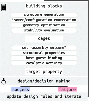
There are several challenges for the computer-driven design of MOCs (Fig. 1). One of the main challenges is structure prediction, which corresponds to predicting the molecular configuration(s) of the self-assembled product(s) from building blocks (organic and metal components). The prediction of solid-state structures of MOCs represents an extremely challenging crystal-structure prediction problem that is yet to be tackled. Although the prediction of solid-state structures of similar, porous organic, molecules has been accomplished,21,22 the introduction of many metal-centres increases the cost and difficulty of these calculations. Further to this, many challenges relate to the issue of the cost and complexity of modelling systems with multiple metals at either the density functional theory (DFT) or classical force field (FF) level. Finally, the introduction of dynamics, including solvent, and complex interactions in the study of host–guest systems poses a great challenge for high-throughput computation and property prediction.
Significant progress in both software and hardware has made the advancements we highlight below possible. As we show, it is now possible to evaluate orders of magnitude more MOC candidates in silico than in the lab and in a shorter time. We outline this article based on a description of MOC structures and recent solutions to the challenges of studying metal-containing systems (Section 2), an introduction of structure generation processes (Section 3), methods for predicting the outcomes and processes of MOC self-assembly (Sections 4 and 5), examples of evaluating MOC host–guest properties (Section 6), and an outlook into the future of MOC design (Section 7).
2 Describing metal–organic cage structures
The modular approach to MOC synthesis from combining metal-containing and organic building blocks allows for their near-infinite tunability. Indeed, MOCs come in a vast array of shapes and sizes and those structures are directly related to their properties. There are several reviews that cover the structural diversity and design principles of MOCs.23–35 MOCs are often described using MnLm nomenclature, where M and L are the metal and organic building block(s), respectively, and n and m are their respective stoichiometries. Hay and co-workers developed a similar nomenclature for MOCs36 that describes a topology defined by the number of vertices, edges and faces. These nomenclature do not directly provide topological or geometrical information, or direct information on the building block connectivity. However, prevalent structures in the literature are often linked with certain topologies and geometries, which is useful for the discussion and design of MOCs based on these templates. Design principles for targeting specific topologies/templates provide the experimental and computational chemist with a good starting prediction.In its simplest form, MOC design stems from understanding the preferred geometry around a metal atom and installing organic components that link multiple metal atoms based upon this.37 The reticular chemistry approach that is so beneficial to the MOF field38 applies to MOCs as well.25 Many of the early advancements in MOC design stem from the assumption that MOC building blocks are rigid, which allows for the use of the “directional bonding” approach (also termed the “ligand-directed” or “symmetry-interaction” approaches). In this approach, the relationship between the bonding vectors of a metal–ligand interaction define the geometry of the connection between building blocks. Therefore, two building blocks with well-defined bonding vectors can be mapped onto idealised MOC structures.37,39 Using rigid components and targeting concave structures has lead to the natural exploitation of high-symmetry geometries (polygons, polyhedra) over the last two decades.24 Fitting with the directional bonding approach, topological selection based on the “bite angle” of the chosen ligand has been crucial in the development of MOC structures. This design principle has been explored in detail by Fujita and co-workers over many articles looking at Pd-based systems40 and builds on the geometrical constraints of the building blocks to determine a favourable topology (Fig. 2). This work shows that the bite angle rule applies generally and has led to the robust development of large homoleptic and heteroleptic MOCs with multiple metal species.29,41–45
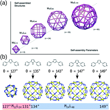 | ||
| Fig. 2 (a) A schematic of the structure relationships observed in a family of roughly spherical coordination polyhedra with general formula MnL2n, where metals (M) and bridging bis(pyridine) ligands (L) are mapped onto the respective vertices and edges of the polyhedra. (b) Critical structural switch between Pd12L24 and Pd24L48 structures in a chemically well-defined system as a function of ligand bite angle. Reprinted with permission from ref. 40. | ||
Even with these design rules in hand, deviations from expectation occur.12,36 This is especially true when ligands deviate, even slightly, from the rigid approximation. For example, a review by Young et al.36 focused on rigid building blocks found that there were many deviations from expectation due to small variations in the preferred geometry of building blocks. Targeting MOCs that mimic the fidelity of enzymes through adaptive or stimuli responsive behaviour requires the introduction of flexibility. There is flexibility at the building block-level, which impacts the self-assembly of MOCs, and flexibility at the cage-level, which impacts MOC properties. Conformationally flexible ligands decrease the preorganisation in a system, which can result in unexpected topological outcomes and a knock-on effect on properties.46–49 Computational design of systems with flexible ligands is an additional challenge because it increases the degrees of freedom in the structure/property prediction.
Modelling and designing MOCs is inherently limited by our capability to model large structures (100s of atoms) with multiple metal-centres. There are a wealth of classical and quantum-mechanical computational approaches for modelling metal-centres50,51 and MOFs17,18,52–54 that may be applicable to MOC systems. There have been recent advances in handling the diversity of metal complexes in a high-throughput fashion. However, the balance of cost vs. accuracy and the need for expert knowledge to properly consider complex electronic properties for different metal species remains a barrier to usage in design workflows. In particular, transition metals present a challenge for DFT methods.55 Part of the challenge of initiating a study of metal-containing systems is whether the chemistry of interest has been implemented, for example does the available software include a FF with the parameters required for the specific metal being modelled, and/or can that system be accurately modelled with readily available techniques. General-purpose FFs ensure this for many metal geometries. For example the Universal Force Field (UFF),56 and the associated extension for MOFs,57,58 and GFN-FF,59 in software such as xtb,60 Open Babel61, Avogadro62 and the General Utility Lattice Program (GULP).63,64 In the case of a FF not containing parameters for the metal of interest, it is common to parameterise FF parameters, which is facilitated by software such as the Metal Center Parameter Builder.65 Similarly, transferable dummy atom models66,67 are approaches to modelling the geometry of metal centres without needing to explicitly describe the bonded interactions between the metal and ligand. In a dummy-atom approach, the metal–ligand interactions are represented as electrostatic interactions between charged dummy atoms (placed around the metal atom in a rigid geometry) and the ligands.
Another approach is generalised energy-based fragmentation (where systems are rationally fragmented into smaller components), which was recently shown to allow the study of large supramolecular systems at much lower cost than modelling the full system.68 Finally, the freely-available GFNn semiempirical density-functional tight-binding methods available in the xtb software (herein, termed GFNn-xTB) and GFN-FF method represent easy-to-use and broadly applicable, low-cost solutions to modelling metal-containing species.59,60,69 This family of methods were parameterised for large parts of the periodic table (Z ≤ 86), and have been shown to be robust for geometries, frequencies and noncovalent interactions of metal-containing species (including MOCs).70 Similarly, advances in robust and low-cost composite DFT methods (e.g., B97-3c and r2SCAN-3c)71,72 provide technically accessible methods applicable to metal-containing structures73 that can reproduce geometries and energetic rankings.
The chemical space available to MOC chemists is vast. On top of the very large chemical space available to organic ligand design, many different metals have been used in experimental studies (see ref. 74). When evaluating approaches to modelling metal-containing systems, the diversity in electronic configuration, spin state, oxidation state and bonding/geometry presents issues in finding a “best-practice” or universal solution.50,75 It is possible to focus on a single “well behaving” metal and on exploring the ligand chemical space. However, this approach is fundamentally limiting. There have been recent advances in exploring transition-metal chemical space by developing cheminformatic-inspired approaches.75,76 Overall, recent literature, including our own work, has shown significant progress in user-friendly, high-throughput approaches for tackling metal-containing systems.
3 Approaches to computational structure generation of metallo-molecular architectures
There are two main approaches to single-molecule structure generation of MOCs: top-down or bottom-up (de novo). In top-down approaches, molecules are built by placing building blocks on a template, while bottom-up approaches, commonly used in drug design, build molecules by fitting fragments into some target geometry. A common issue for both approaches that the user must be aware of is that arbitrarily combining components can diminish synthesisability.77,78 The top-down approach benefits from being based on templates, which inherently encodes design rules into the process and the building blocks used.3.1 Bottom-up or de novo structure generation
The Hay group developed a bottom-up, de novo approach to transition-metal complex and cage structure generation that moves away from the limitations of idealised geometries and bond-vector approaches.36 Their approach is implemented in their free software, HostDesigner,79,80 which has been used for designing metal-ion binders to MOCs.77,81–87 Their structure-based algorithms work by docking “linking fragments” (from a library) between the target “complex fragments”, then covalently connecting those fragments, which produces new molecules in active conformations. All possible connection points, conformations, linking isomers and stereoisomers are explored in the assembly algorithm (e.g., the rotations and translations of the two fragments in Fig. 3a). Fig. 3b shows a MOC construction workflow starting from two complex fragments. In HostDesigner, Hay and co-workers define a fitness function for the de novo generation of a host based on the fit between bonding vectors and whether steric clashes occur. Recent iterations use a scoring function that considers multiple properties: (1) binding energy with the guest, (2) conformational strain and (3) entropic cost to binding, all of which can be evaluated with FF calculations or empirically.77 They show the utility of this approach in the design of M4L6 MOCs88 and ion-pair ML3A helicates (A is an anion).89 Custelcean et al. designed a new Ni4L6 sulfate receptor (Fig. 3(b)), which was the first example of the design of a MOC lined with urea binding sites.88 From their top candidates, they selected and successfully synthesised one that outperforms other synthetic sulfate receptors. For a tutorial review into using HostDesigner, see ref. 84 and the documentation with the software.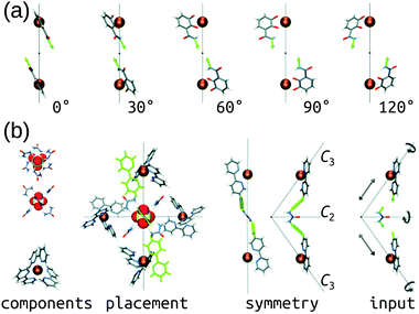 | ||
| Fig. 3 (a) Vector poses for the input fragment obtained by vertex rotation about the C3 axis. Amount each vertex is rotated from the initial position is given below each structure. (b) Generation of HostDesigner starting structure. (left) Structure of the [SO4(urea)6]2− complex, viewed down the C3 (top) and C2 (bottom) axes, and of the [Ni(bpy)3]2+ complex, taken from crystal structure coordinates (CSD REFCODE: CUHVUW). (middle-left) Placement of [SO4(urea)6]2− and [Ni(bpy)3]2+ components into a T symmetric assembly. (middle-right) Design target is an edge molecule illustrated with generic linkages (green cylinders) between the bpy and urea groups. (right) Input fragment, with geometric drives depicted by grey arrows. Reprinted with permission from ref. 36. | ||
3.2 Top-down structure generation
Top-down methods, where building blocks are placed on predefined geometries or topologies, are often used in the generation of solid-state porous materials.90–94 Such approaches benefit from the starting points provided by existing design principles and structures. We have implemented a topology-based approach in our software, stk (https://github.com/lukasturcani/stk), which we recently improved to handle metal–organic systems.95stk is an open-source, Python toolkit that provides modular, easy-to-use functionality for generating chemical structures by placing building blocks on a “topology graph”. A topology graph defines an idealised geometry of “vertices” and “edges” (edges connect vertices), where the vertices and edges define independent alignment and reaction processes to perform on building blocks (which are placed on vertices) during construction. This approach is well suited to the descriptions of MOC structures described above. Fig. 4 shows a simplified workflow of stk construction. Some crude, rigid body optimisation protocols are available within stk, but in general, the initially constructed stk molecular models require further optimisation. For this, we have developed the stko package (https://github.com/JelfsMaterialsGroup/stko)96 that takes in stk molecules and can perform property evaluations (including single-point energy calculations, geometrical analysis) and geometry optimisations. Currently, stko includes wrappers for RDKit,97 GULP,63,64 Macromodel98 and xtb.60,69 We have used GULP and xtb in our workflows, which allow for conformer searches and geometry optimisations of MOCs.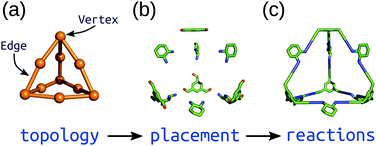 | ||
| Fig. 4 Schematic of the construction process of an organic cage in stk starting from a (a) topology graph of vertices connected by edges. The supplied building blocks are (b) placed and aligned on the topology, and then (c) “reactions” are performed between them. Reprinted from ref. 95, with the permission of AIP Publishing. | ||
stk can construct many different molecule classes beyond cages, including polymers, macrocycles, metal complexes, rotaxanes, host–guest complexes and extended porous materials (COFs and MOFs). One of the key features is the transferability of stk molecules, where a constructed molecule can then be used as a building block in the construction of a new molecule in a hierarchical process. Importantly, stk is “chemistry agnostic” in the sense that any building block can be placed on any topology graph. Furthermore, stk can construct cages with arbitrary ligand placements and alignments, allowing for heteroleptic cage construction and the consideration of configurational isomers.99 This feature is especially crucial for MOC construction because the metal complex often needs to be constructed prior to cage construction (Fig. 5a) with a specific stereochemistry. Fig. 5b shows hierarchical model construction of a Pd2L4 cage with rotaxane-based ligands (code available at https://github.com/andrewtarzia/stk-examples).100 Finally, we updated the in-built optimisation options in stk to include a host–guest conformer generator that can very quickly optimise the position and orientation of guest(s) within a host.
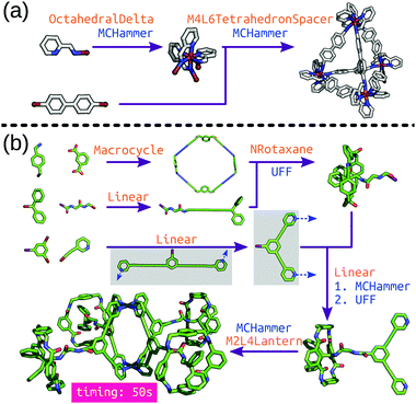 | ||
| Fig. 5 Hierarchical construction (a) of a Δ-M4L6 cage from an octahedral complex (this code was taken directly from the stk documentation) and (b) of a metallo-[5]rotaxane from ref. 100. Each purple arrow is a construction process, orange text is the topology graph used and blue text is the optimisation process used. The grey boxes show the (left) initial structure generated by stk, which must undergo conformer sampling to find the (right) conformer used for cage construction. MCHammer is a low-cost geometry optimisation function implemented in stk; further optimisation would be required. | ||
Also using a top-down approach, Young et al. developed cgbind (available at https://github.com/duartegroup/cgbind), an open-source Python toolkit for the construction and evaluation of MOCs (a web-app is also available at http://cgbind.chem.ox.ac.uk).101 They show that cgbind generates structures close to crystal structure conformations without any external software, which is a huge benefit to high-throughput screening. cgbind also provides a series of analysis algorithms and can generate host–guest complexes. In a comparison to literature binding data, they show good performance of their fast binding-energy evaluators compared to semiempirical methods for a series of MOCs and guests. Fig. 6 shows a workflow for MOC screening they implement using cgbind, where ligands are generated in a combinatorial fashion based on “end”-“link”-“center”-“link”-“end” structures. They screen the possible 13104 Pd2L4 cages based on the cage geometry, the size of the cage, the host–guest binding energy (based on a quinone guest), the formation energy of the cage (calculated using GFNn-xTB) and, finally, the synthetic accessibility102 of the ligand.
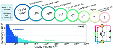 | ||
| Fig. 6 Filtering process used to find the three optimal hosts for benzoquinone based on simple geometric criteria, tight-binding DFT calculations, and synthetic accessibility of the constituent linker molecules. Adapted with permission from ref. 101. Copyright 2020 American Chemical Society. | ||
3.3 Precursor generation
The generalisability of top-down approaches means that vast precursor libraries can be easily explored (e.g., Fig. 5(b) and 6). However, the generation of transition metal complex structures is a developing field in itself and generating precursor building blocks of metal complexes is not trivial. We have introduced common supramolecular metal geometries into stk (e.g., octahedral; Fig. 5a).95 There are also multiple software for generating 3D coordinates of transition metal complexes and to perform de novo generation103 of metal complexes: DENOPTIM,104molSimplify105 and Molassembler.106 For the organic components, free software like RDKit97,107,108 or Open Babel61 can easily generate 3D conformers from 2D representations of molecules. Rational precursor selection should be an integral part of material design to avoid synthesisability issues.784 Predicting topology and configuration of metal–organic cages
Much of the computational effort spent on MOC studies, so far, has been on trying to determine or rationalise the outcome of a self-assembly process. Assuming the thermodynamic product is formed, the connectivity of the building blocks and their stoichiometric ratios define the possible self-assembly outcomes (topologies). For example, mixing square-planar Pd(II) (M) and ditopic N-donor ligands (L) in a 1![[thin space (1/6-em)]](https://www.rsc.org/images/entities/char_2009.gif) :
:![[thin space (1/6-em)]](https://www.rsc.org/images/entities/char_2009.gif) 2 ratio should, under thermodynamic conditions, produces a MnL2n topology. Still, predicting which topology forms from precursors remains a challenge as the topological preference (and/or the self-assembly process) is sensitive to solvent,109 counter/co-ions,110 and building block geometry and flexibility. To identify the preferred structure for an arbitrary ligand (or set of ligands), it is possible to directly calculate the relative energy of all possible topologies. However, the energy differences between configurations are often small and, for example, competing ligand–ligand interactions are on the same energy scale as those driving MOC self-assembly. Therefore, any approach would need to be sufficiently accurate to distinguish between the multiple low-lying energetic states while also being sufficiently efficient to be practical for prediction. Further complicating this issue is when multiple self-assembled structures are present in equilibrium or can be selected for by changing the environment, highlighting their closeness in relative energy and difficulty in distinction.111 A specific example of this problem is the “triangle vs. square equilibria” of Pd-based polygons,112 where the triangle is entropically favoured and the square is enthalpically favoured; the triangle becomes enthalpically favoured as the ligand is made more flexible.113 Uehara et al. explored the factors controlling the formation of Pd-based square and triangle structures based on a series of bridging ligands.113 They showed that DFT calculations considering implicit solvation can reproduce the effect on the equilibrium of steric crowding, bridging ligand length and solvent effects.
2 ratio should, under thermodynamic conditions, produces a MnL2n topology. Still, predicting which topology forms from precursors remains a challenge as the topological preference (and/or the self-assembly process) is sensitive to solvent,109 counter/co-ions,110 and building block geometry and flexibility. To identify the preferred structure for an arbitrary ligand (or set of ligands), it is possible to directly calculate the relative energy of all possible topologies. However, the energy differences between configurations are often small and, for example, competing ligand–ligand interactions are on the same energy scale as those driving MOC self-assembly. Therefore, any approach would need to be sufficiently accurate to distinguish between the multiple low-lying energetic states while also being sufficiently efficient to be practical for prediction. Further complicating this issue is when multiple self-assembled structures are present in equilibrium or can be selected for by changing the environment, highlighting their closeness in relative energy and difficulty in distinction.111 A specific example of this problem is the “triangle vs. square equilibria” of Pd-based polygons,112 where the triangle is entropically favoured and the square is enthalpically favoured; the triangle becomes enthalpically favoured as the ligand is made more flexible.113 Uehara et al. explored the factors controlling the formation of Pd-based square and triangle structures based on a series of bridging ligands.113 They showed that DFT calculations considering implicit solvation can reproduce the effect on the equilibrium of steric crowding, bridging ligand length and solvent effects.
Poole et al. developed a FF and structure/topology prediction workflow for PdnL2n (n: 3–30) structures.114 They predict the topologies of cages self-assembled from four different ligands (Fig. 7a). Given an FF that accurately reproduces cage free energies, they calculated the relative energy and Boltzmann statistical weight of each topology to make their prediction of the most likely topology (Fig. 7b). For ligands LFu and LTh, they reproduce the major topology preference and uncover the presence of new or intermediate species, which they support with their own experimental work. Considering the more complex case of heteroleptic systems, they reproduce the experimentally confirmed critical concentration of ligands LFu and LTh at which a Pd24L48 topology becomes preferred over the Pd12L24 topology. For ligands LEx and LEn, they reproduce the effect of endohedral functionalisation in favouring larger species than their bite angle would suggest; this result was supported by experiments. Their work reproduces and expands upon experimental data and shows that by providing atomistic insight into intermediate topologies and ligand dynamics, they can strengthen design principles toward rational design of MOCs. Indeed, they used this approach to help guide experimental control of the self-assembly of platinum architectures.47,115 However, the a priori knowledge of possible topologies and the number and cost of simulations remain barriers for this approach.
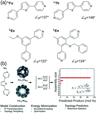 | ||
| Fig. 7 (a) Structures of the bipyridyl linker molecules used in this study. Bend angles, ∠B, are estimated from B3LYP/def2-TZV minimized structures. (b) Flow chart for topological prediction of homoleptic assemblies featuring the formation of homoleptic PdxLFu2x assemblies. The linker structure is used to construct a library of possible assembly outcomes, which are subjected to a simulated annealing and structural optimization procedure using implicit solvation. The resulting minimum energies, E, are treated as microstates, and the topological distribution is determined using Boltzmann statistics with a weighting factor ‘n’ corresponding to the number of linker components in the assembly. Reprinted with permission from ref. 114. | ||
A new level of complexity comes into play when considering the self-sorting116 of configurational isomers14 or stereoisomers.117,118 While design rules can guide structural predictions, unexpected behaviour often occurs, resulting in fascinating MOCs.12 Therefore, direct structure prediction, without the bias of predetermined outcomes, is necessary for future property prediction and design processes. Unsymmetrical ligands, for example, introduce complexity because multiple isomers can form during the self-assembly process. Recent work with unsymmetrical ligands highlights the combinatorial explosion that can occur when forming higher nuclearity topologies (Fig. 8).119,120 For example, there are 112 possible isomers for Pd6L12 structures that would need to be evaluated per ligand. Li et al. suggest that geometrical matching can rationalise self-sorting in their complex system. In our work,121 steric, geometrical and a mixture of steric and geometrical control is introduced to rationally favour a specific isomer. Studies like the above begin the path toward design rules for asymmetrical MOCs. We,121 and Yu et al.120 supported our findings with DFT calculations. However, applying similar methods to higher nuclearity species with many more isomers would be very expensive.
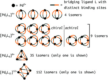 | ||
| Fig. 8 Potential isomers for metal–ligand assemblies of the general formula [PdnL2n]2n+ (n = 2, 3, 4, or 6). The isomers differ in the relative orientation of the bridging ligands L, which have two distinct binding sites. The number of isomers increases from 9 → 16, 35 → 68, and 112 → 186 if enantiomers are considered as well. Adapted from ref. 119. | ||
Furthering our exploration of these systems, we implemented a joint computational and experimental evaluation workflow for Pd2L4 MOCs formed from unsymmetrical ligands.99 In this example, we assumed a single topology (Pd2L4) was most likely to form based on enthalpic arguments. We targeted a low-cost, “good enough”, prediction of the self-assembly outcome to guide experimental decision making. Searching for ways to lower the cost, we found that the predictions of cis isomer preference by GFN2-xTB69 agreed with DFT and could reasonably predict whether an unsymmetrical ligand would self-sort into a single of four possible isomers (Fig. 9a). This allowed us to use a workflow based on FF and semiempirical methods for cage conformer searches, geometry optimisation and relative energy evaluation, resulting in structure generation in hours instead of days. We used stk95 to construct 60 unsymmetrical ligands and their respective cage isomers (four per ligand, 240 cages in total) from a series of hand-picked ligand building blocks. When coupled with geometrical heuristics of MOC stability (e.g., “how square-planar is the metal centre?”), we ranked candidate ligands for their likelihood of forming only a single isomer in solution. Fig. 9b and c shows the five cages evaluated experimentally, and their respective cis isomer preference. Our predictions of self-sorting failed in at least one instance (4B3 did not self-assemble into a single isomer based on experimental validation). However, we purposefully tested around the previously found threshold for cis isomer preference to further strengthen our design principles. Additionally, our approach is general and counteracts the increased computational effort expected for more complex systems.
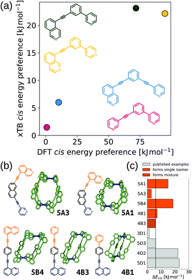 | ||
| Fig. 9 (a) Comparison of GFN2-xTB (DMSO) and DFT (PBE0/def2-SVP/D3BJ/CPCM(DMSO)) energy difference between the cis and next most stable isomer of cages formed in ref. 121 from the ligands 3D1 (crimson), 4D2 (yellow), 5D1 (dark green) and 5D3 (blue). (b) GFN2-xTB optimised structure of the cis isomer of selected cage ligands (hydrogen atoms omitted; C green, N blue, Pd cyan). Cage ligands are shown next to each structure with orange and navy indicating inequivalent ligand fragments. (c) cis isomer GFN2-xTB (DMSO) stability (ΔEcis) for all published121 and newly selected ligands (patterns distinguish their self-assembly outcomes). Adapted from ref. 99. | ||
In summary, the structure prediction of MOCs can require a large number of calculations due to the configurational freedom. Overall, it is likely necessary to consider a very large number of possible topologies/isomers when predicting MOC structures. Using design rules and simplified models can make MOC structure prediction more tractable by narrowing the available search space and decreasing the cost of calculations. In an example approach, Yoshida et al. developed an effective model Hamiltonian that can help make MOC topology evaluation more efficient.122 However, to develop and apply low-cost methods requires robust data to build from, which emphasises the need for experimental and computational collaboration.
5 Understanding the self-assembly process
The self-assembly process of MOCs corresponds to a complex landscape of potential intermediates that, remarkably, produces a single species in many cases. This is the result of the large enthalpy gains designed into the systems that counter the entropy losses of forming ordered structures.123 By understanding the self-assembly process one can access and evaluate the potential intermediates via methods like above. On this path, substantial work done by Hiraoka and co-workers in quantitative (QASAP) and numerical (NASAP) analysis of self-assembly processes, with a specific focus on Pd and Pt-based MOC assembly,124,125 provides a map of complex cage-assembly processes. Their numerical, reaction-network analysis can reproduce experimental intermediate populations and uncover kinetically trapped species.126–128 Another approach is to directly model the self-assembly process. Yoneya et al. developed an MD simulation protocol for modelling the self-assembly of Pd-based MOCs (Pd6L8129 and Pd12L24130 cages). They implement a nonbonded dummy atom model66,67 to represent the metal atoms and maintain bond reversibility, and a coarse-grained (CG) solvent model that allows for cage assembly to be observed on MD time scales. Under the right conditions (determined through trial-and-error), they are able to explore the stages of MOC self-assembly in atomistic detail, providing further understanding and uncovering possible intermediates. While studying Pd12L24 assembly,130 they found that kinetic trapping occurs at smaller-sized clusters (e.g., Pd6L12, Pd8L16, and Pd9L18), which can be decreased by increasing ligand bite angle (reproducing experimental findings). This model has been applied to study the assembly and stability of Pd-based MOCs,131–133 Hg-Based MOCs134 and MOFs.135 This approach is fundamentally generalisable because the dummy-atom approach is applicable to other metals.66,67,136,1376 Exploring host–guest systems and confinement in metal–organic cages
The main applications of MOCs stem from their solid-state or solution-phase interactions with guest molecules to form host–guest complexes. How to compute the relevant properties for these applications will be discussed next. While the systems explored below are relatively simple host–guest complexes, very complex (e.g. multiple guest) complexes are experimentally viable and of interest to the community due to there applications in catalysis and sensing.4 There are multiple barriers (balancing cost and accuracy) to the computational design of host–guest complexes, such as, considering flexible systems, explicit solvation, and high nuclearity systems. We focus on modelling host–guest interactions of already formed cages. However, there are examples of the impact of host–guest interactions in templating the self-assembly process.1346.1 Describing an intrinsic cage pore
Rebek's rule provides a design rule for host–guest systems based on pore volume, where optimal binding occurs for a packing coefficient in the range of 0.55 ± 0.09.138 Importantly, strong intermolecular interactions or shape-effects cause deviations from this rule. The volume and shape of the pore is inherently linked to a MOCs host–guest properties. There are multiple examples of software available for analysing single-molecule pores, such as: pyWindow,139 MoliPor,140 and VOIDOO.141 Rizzuto et al. show an example of the use of VOIDOO to calculate pore volumes and help rationalise the entropic self-sorting outcome in heteroleptic MOCs.142 We have developed pyWindow, which uses a spherical probe for cavity measures and, like MoliPor,140 includes a sampling algorithm for detecting windows.139 Geometrical analyses of the cage and pore structure are cheap and insightful heuristics for structure–property relationships. For example, we coupled pyWindow and a geometrical measure based on the displacement of Pd centres (termed “ΔPd” in ref. 99) to measure the size and anisotropy of the cis-Pd2L4 cages we generated from unsymmetrical ligands.99 Also, Young et al. measured the twist of Pd2L4 cages during MD simulations to correlate cage flexibility to guest binding affinity.143Fig. 10 shows example geometrical descriptors in Pd2L4 cages. Building on this, it is useful to produce energetic maps of the pore space (e.g., an electrostatic potential).101,144–146 Finally, Rebek and co-workers asked “where do the holes in the structure end?… Where do the atoms end?”.138 The description of an intrinsic pore is inherently limited when assuming rigidity, and when trying to define its start and end points. Importantly, there are multiple examples of external binding sites in MOCs (e.g., ref. 142 and 147). Therefore, we expect that pore representations that include the external surface and shape of the MOC will be physically useful.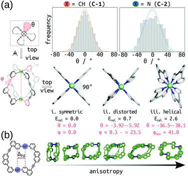 | ||
| Fig. 10 (a) (top) Twist angle (Θ) frequency for C-1 and C-2 calculated in explicit DCM solvent, over 30 ns of cumulative MD simulations. (bottom) local minima for C-1 (i–iii) calculated at the PBE0-D3BJ/def2-SVP level of theory. Relative energies (Erel) in kcal mol−1. Adapted with permission from ref. 143. Copyright 2020 American Chemical Society. (b) Geometrical measure of anisotropy (ΔPd) used in ref. 99 with example cage structures of increasing anisotropy. | ||
6.2 Calculating guest binding affinity and mapping encapsulation dynamics
Calculating the binding energy of host–guest systems is an open challenge. The SAMPL blind challenges highlight multiple issues in a summary of “SAMPL7: Host–Guest challenge” including: charge, method complexity, multimeric systems, solvent/salt type and concentration.148 As stated in ref. 149, several variables guide the prediction of binding affinities: (1) host cavity volume, (2) guest volume, (3) ratio of guest and host volume (packing fraction), (4) involvement of solvent, (5) a combination of all of the above. All of these variables are dynamic and likely to change as a function of binding, where host–guest interactions can modify the cage structure and confinement effects. Even at the state-of-the-art quantum-mechanical level, recent work showed discrepancies between two approaches for large host–guest systems (132 atoms).150 DFT approaches can produce good absolute and relative comparisons to experimental free association enthalpies for relatively small organic host–guest complexes.151 However, quantitative insight from DFT still requires an expert touch, long compute times and some assumed conformational rigidity. Spicher et al. reported benchmarks for small molecule binding evaluation in MOFs, MOCs and porous organic cages using GFNn-xTB/GFN-FF.152 Importantly, the low-cost GFNn-xTB methods performed well throughout (including charged systems) and present generally-applicable methods. Löffler et al. used DFT and simplified cluster models to explore neutral guest binding (studying 50 guests) in interpenetrated Pd2L4 cages.144 Young et al. found good agreement between experimental and computed Pd2L4-quinone binding affinities when using geometries optimised at the DFT-level but found a system and geometry optimisation-method dependence on model performance.143 They find that the impact of the metal (Pd(II)) in these systems mostly results in polarisation of the ortho-pyridine hydrogen atoms, leading to favourable quinone binding, which highlights the benefit of applying a quantum mechanical representation to the system because polarisation is not modelled in most classical approaches.For the high-throughput evaluation of many candidates and large, dynamic systems, classical FF approaches are ideal, which has been shown continuously in their use in docking studies for protein–ligand binding. However, FF approaches are limited by chemical scope, especially for metal-containing species, and are less accurate models of nonbonded interactions (e.g., lacking polarisation or context dependant parameters). Multiple recent papers149,153–156 explored the dynamics of encapsulation for a variety of MOCs and guests using FF approaches. In these examples, the benefit of considering dynamics of the host and guest are made clear; MOC flexibility is critical to the guest binding process, where the MOC often adapts to the guest. Classical simulations provide access to free energy landscapes, which provide structure–property relationships throughout dynamic processes. By combining NMR experiments and MD simulations, García-Simón et al. reconstruct the encapsulation of fullerenes into a Zn–porphyrin Pd-based MOC (Fig. 11).156 Additionally, the modifiable or “toy” nature of FF parameters allows for the study of implicit structure–property relationships. For example, Pesce et al. extracted design principles by artificially modifying the size of the guest: e.g., host–guest binding energy or extent of crowding correlates with guest release rate and isomerisation rate.154 Importantly, each of the above papers required FF parametrisation for at least one metal species and used enhanced sampling to access the time-scales relevant to complexation.
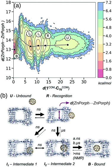 | ||
| Fig. 11 (a) Reconstructed free energy landscape of the spontaneous encapsulation process of C70 in the Zn and Pd-based tetragonal prismatic nanocapsule obtained from an accumulated simulation time of 75 μs of MD simulations. The landscape has been reconstructed using the host centre-of-mass to C70 centre-of-mass distance (d(1COM–C70COM)) and Zn⋯Zn distances (shown schematically by a purple arrow in (b)). (b) Molecular representation of five relevant metastable states: unbound (U), recognition (R), intermediate 1 (I1), intermediate 2 (I2), and bound (B) states. The width of the arrows in (b) indicates the most frequent events observed and the time scales implied from MD simulations and NMR experiments. Adapted with permission from ref. 156. Copyright 2020 American Chemical Society. | ||
Borrowing from the organic drug-discovery field, the Ward group49 implemented a docking approach to find candidate guests for their M8L12 MOC. Their capabilities hinge on the data obtained from their many experimental studies into this MOC.157 They initially trained a scoring function for rigid host and guest molecules on 54 data points (using the GOLD software158).159 Importantly, they only achieved good agreement when they accounted for the loss of conformational freedom due to binding in the scoring function. They support their findings by predicting (and experimentally validating) new guests from a screen of 3000 candidates. Building on this, Taylor et al. studied the effect of flexibility on guest binding in the same MOC.160 Based on new experimental data on flexible guests they retrained and improved their scoring function. Fig. 12 shows the cage structure and parity plots of the experimental vs. calculated binding constants from these two works. There are two limitations to this work: (1) they assume rigidity in their host complex and (2) a scoring function must be developed for each new host. However, their approach allows for the translation of protein–drug binding methods to the design of host–guest complexes with this MOC and other MOCs, given sufficient training/similar host–guest interactions.
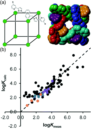 | ||
| Fig. 12 (a) (left) Sketch and (right) crystal structure of host cages Co8L12 studied in ref. 159 and 160 (R = H for crystallographic studies, R = CH2OH for measuring binding constants of guests in water). Comparison of experimental binding constants for the training set (Kexpt) with calculated binding constants (Kcalc) in ref. 160. Black data points are the same molecule set as in ref. 159. Orange, blue and purple data points are flexible molecules. Adapted from ref. 160. | ||
6.3 Catalysis
The design of MOCs for catalysis focuses on tuning of the cavity microenvironment to optimise reaction conditions, akin to designing synthetic enzymes.48,161,162 The role of a MOC in catalysing a reaction is often linked to their affinity for the reactant(s), transition state, or product(s). MOC catalysis can be the result of internal or external chemistry, and/or confinement effects.4,147,163–165 There are many reviews on the topic of MOC-based or supramolecular catalysis,7,8,166–168 and in silico (transition metal) catalyst design.76 To completely capture the catalytic activity of MOCs requires detailed models (including solvent, counter/co-ions), which are costly and complex to implement. However, simplified models and heuristics for catalytic activity have been successfully uncovered, and subsequently applied. For example, through multiple computational studies into the catalytic activity of Raymond's Ga4L6 MOC,169 multiple design principles have been uncovered. Frushiceva et al. highlight the complexity of the potential paths of catalysis in this system and show the importance of the electrostatic stabilisation of the transition state.170 Welborn et al. show that the electric field, and how it changes upon confinement, provides a descriptor of catalytic activity.171,172 Multiple examples173–177 show the importance of transition-state stabilisation and solvent reorganisation under confinement to catalytic performance of this cage over multiple reactions.Extending to multiple cage and substrate combinations, Young et al. developed an efficient DFT-based protocol for predicting the catalytic activity of Pd2L4 cages for Diels–Alder reactions based on quinone substrates.143 They begin by computationally confirming the catalytic activity of two isostructural Pd2L4 cages, explored experimentally by the Lusby group.162 Their protocol for calculating binding affinity and catalyic activity allows them to confirm the experimental rationalisation for the differing cage catalytic activity, highlighting the effect of sterics and flexibility. Given this rationalisation for a single reaction, they look to using their method on new substrates and testing cost-reducing assumptions toward high-throughout methods. Their approach achieves 80% accuracy with a ten-fold decrease in computation time. Coupling this with their recent work in software for metallocage construction,101 automated reaction-energy profile calculations178 and reactive FF learning (applied to Pd2L4 MOCs),179 they outline significant steps toward automated MOC design for catalysis. However, calculating host-based catalytic activity remains difficult to generalise to other cage/substrate systems and perform at low-cost.
7 Summary and outlook
We have outlined the recent progress in applying computational design processes and methods to MOCs. Much of this progress includes the development of software for tackling the structure generation and diversity (regarding the metal centre/geometry/electronic structure and the chemical diversity of organic components) of metal-containing structures. In many examples, FF/model parametrisation specific to the cage of interest was required, which limits transferability over chemical space. The development of “best-practice” guidelines for handling MOCs and metal-containing structures is pertinent to the use of design workflows in this field. An interesting approach to solving this process looks at using computational models to help design/monitor the design workflow by scoring the “safety” of calculation methods (based on DFT).180 Automated approaches, like ours in stk,95,99 and those of the Duarte,101,143 and Hay groups80 show progress in developing generalisable design workflows to explore MOCs. Overall, the development of low-cost cheminformatic, semiempirical and DFT approaches using large and diverse benchmark sets can provide robust and broadly applicable methods for studying MOCs with reasonable accuracy, which is crucial for high-throughput design processes.Computational design workflows can be envisaged as feedback loops, where they are informed by and then inform design principles. Design principles are extracted by exploring chemical space and are vital for improving computational predictions. Unfortunately, many existing MOC design principles rely on a rigid picture, which quickly becomes insufficient; it is the flexibility of MOCs that provides much of their capability. Even for seemingly rigid structures, the binding of guests was shown to alter the MOC structure. Therefore, computational design must go toward dynamic pictures of MOCs while maintaining high-throughput efficiency. Advances in enhanced sampling approaches and coarse-grained models make it possible to explore potential energy surfaces of large systems, while capturing changes in structure and properties. Such a complete map can help understand the evolving and complex behaviour of functional MOCs. Additionally, the increased configurational flexibility arising from heteroleptic or anisotropic MOCs quickly results in a combinatorial explosion when attempting structure prediction. Therefore, generalisable and efficient methods serve the present and future needs of MOC chemists.
Translating tools from the solid-state materials and pharmaceuticals fields provides potential solutions. For example, we saw the power of training docking software for predicting host–guest binding affinities.159,160 However, this work was based on many years of experimental studies on a single cage system,49 which leads to a significant challenge in MOC property prediction: the collation and standardisation of experimental data for validating against. As of yet, there are no published databases of MOCs (including structures or properties) like there are for drug-like molecules and inorganic materials, which would be necessary for training robust models for property evaluation.
Providing structure and property databases allows for the application of data-science techniques and the use of machine-learning or artificial intelligence. Indeed, the flexibility of machine-learning approaches is well fit to the complexity of predicting properties of transition metals.181 Recent work by the Kulik group, and others, has focussed on cheminformatic-inspired approaches to transition-metal complex discovery aimed at mimicking the success of organic drug discovery platforms.75 Similarly, structure–property relationships can quickly find new applications for existing MOCs and help design new MOCs. Advances in artificial intelligence methods allow for the design of new molecules/materials while optimising multi-objective functions. Therefore, robust structure generation and property prediction methods are needed to allow their application to MOCs. Putting this all together will provide the generation and application of data at significantly faster rates than available in the lab and provides new insight into future design processes and decisions.
Finally, the full potential of computational tools can only be unlocked if they are usable and understandable by chemists with ranging programming or computational backgrounds. Open-source and easy-to-use software facilitates uptake by other research groups and avoids wasted development efforts, and much of our focus in software development for materials design has been to simplify the user-experience to this end. This means that rudimentary or initial calculations can be undertaken by chemists with limited computational expertise. Even where calculations do remain the domain of the expert computational chemist, the input of experimental chemists is crucial for decision-making during the process. An improved understanding of computational tools, their possibilities and limitations, helps to improve communication between collaborators. Therefore, by ensuring these steps, we expect to see more fruitful joint computational and experimental research.
Conflicts of interest
There are no conflicts of interest to declare.Acknowledgements
K. E. J. acknowledges the Royal Society for a University Research Fellowship and a Royal Society Enhancement Award 2018, and the ERC through Agreement No. 758370 (ERC-StG-PE5-CoMMaD). We thank Drs Jamie Lewis and Emma Wolpert for commenting on drafts of the manuscript.Notes and references
- P. Muller, Pure Appl. Chem., 1994, 66, 1077–1184 Search PubMed.
- H. Vardhan, M. Yusubov and F. Verpoort, Coord. Chem. Rev., 2016, 306, 171–194 CrossRef CAS.
- D. Zhang, T. K. Ronson and J. R. Nitschke, Acc. Chem. Res., 2018, 51, 2423–2436 CrossRef CAS PubMed.
- F. J. Rizzuto, L. K. S. von Krbek and J. R. Nitschke, Nat. Rev. Chem., 2019, 3, 204–222 CrossRef.
- N. Ahmad, H. A. Younus, A. H. Chughtai and F. Verpoort, Chem. Soc. Rev., 2015, 44, 9–25 RSC.
- K. Suzuki, M. Kawano, S. Sato and M. Fujita, J. Am. Chem. Soc., 2007, 129, 10652–10653 CrossRef CAS PubMed.
- Y. Fang, J. A. Powell, E. Li, Q. Wang, Z. Perry, A. Kirchon, X. Yang, Z. Xiao, C. Zhu, L. Zhang, F. Huang and H.-C. Zhou, Chem. Soc. Rev., 2019, 48, 4707–4730 RSC.
- G. Olivo, G. Capocasa, D. D. Giudice, O. Lanzalunga and S. D. Stefano, Chem. Soc. Rev., 2021, 50, 7681–7724 RSC.
- D. Zhang, T. K. Ronson, Y.-Q. Zou and J. R. Nitschke, Nat. Rev. Chem., 2021, 5, 168–182 CrossRef CAS.
- N. Hosono and S. Kitagawa, Acc. Chem. Res., 2018, 51, 2437–2446 CrossRef CAS PubMed.
- Y. Sun, C. Chen and P. J. Stang, Acc. Chem. Res., 2019, 52, 802–817 CrossRef CAS PubMed.
- S. Saha, I. Regeni and G. H. Clever, Coord. Chem. Rev., 2018, 374, 1–14 CrossRef CAS.
- S. Pullen, J. Tessarolo and G. H. Clever, Chem. Sci., 2021, 12, 7269–7293 RSC.
- A. E. Martín Díaz and J. E. M. Lewis, Front. Chem., 2021, 9, 456 Search PubMed.
- D. Bardhan and D. K. Chand, Chem. – Eur. J., 2019, 25, 12241–12269 CrossRef CAS PubMed.
- J. D. Evans, K. E. Jelfs, G. M. Day and C. J. Doonan, Chem. Soc. Rev., 2017, 46, 3286–3301 RSC.
- J. D. Evans, G. Fraux, R. Gaillac, D. Kohen, F. Trousselet, J.-M. Vanson and F.-X. Coudert, Chem. Mater., 2017, 29, 199–212 CrossRef CAS.
- A. Sturluson, M. T. Huynh, A. R. Kaija, C. Laird, S. Yoon, F. Hou, Z. Feng, C. E. Wilmer, Y. J. Colón, Y. G. Chung, D. W. Siderius and C. M. Simon, Mol. Simul., 2019, 45, 1082–1121 CrossRef CAS PubMed.
- R. Pollice, G. dos Passos Gomes, M. Aldeghi, R. J. Hickman, M. Krenn, C. Lavigne, M. Lindner-D'Addario, A. Nigam, C. T. Ser, Z. Yao and A. Aspuru-Guzik, Acc. Chem. Res., 2021, 54, 849–860 CrossRef CAS PubMed.
- R. L. Greenaway and K. E. Jelfs, Adv. Mater., 2021, 2004831 CrossRef CAS PubMed.
- E. O. Pyzer-Knapp, H. P. G. Thompson, F. Schiffmann, K. E. Jelfs, S. Y. Chong, M. A. Little, A. I. Cooper and G. M. Day, Chem. Sci., 2014, 5, 2235–2245 RSC.
- M. Bernabei, R. Pérez-Soto, I. G. Garcia and M. Haranczyk, Mol. Syst. Des. Eng., 2019, 4, 912–920 RSC.
- L. R. MacGillivray and J. L. Atwood, Angew. Chem., Int. Ed., 1999, 38, 1018–1033 CrossRef CAS PubMed.
- S. R. Seidel and P. J. Stang, Acc. Chem. Res., 2002, 35, 972–983 CrossRef CAS PubMed.
- D. J. Tranchemontagne, Z. Ni, M. O'Keeffe and O. M. Yaghi, Angew. Chem., Int. Ed., 2008, 47, 5136–5147 CrossRef CAS PubMed.
- R. Chakrabarty, P. S. Mukherjee and P. J. Stang, Chem. Rev., 2011, 111, 6810–6918 CrossRef CAS PubMed.
- M. M. J. Smulders, I. A. Riddell, C. Browne and J. R. Nitschke, Chem. Soc. Rev., 2013, 42, 1728–1754 RSC.
- M. Han, D. M. Engelhard and G. H. Clever, Chem. Soc. Rev., 2014, 43, 1848–1860 RSC.
- N. Ahmad, A. H. Chughtai, H. A. Younus and F. Verpoort, Coord. Chem. Rev., 2014, 280, 1–27 CrossRef CAS.
- T. R. Cook and P. J. Stang, Chem. Rev., 2015, 115, 7001–7045 CrossRef CAS PubMed.
- N. B. Debata, D. Tripathy and H. S. Sahoo, Coord. Chem. Rev., 2019, 387, 273–298 CrossRef CAS.
- B. S. Pilgrim and N. R. Champness, ChemPlusChem, 2020, 85, 1842–1856 CrossRef CAS PubMed.
- E.-S. M. El-Sayed and D. Yuan, Chem. Lett., 2020, 49, 28–53 CrossRef CAS.
- S. Lee, H. Jeong, D. Nam, M. S. Lah and W. Choe, Chem. Soc. Rev., 2021, 50, 528–555 RSC.
- A. V. Virovets, E. Peresypkina and M. Scheer, Chem. Rev., 2021, 121, 14485–14554 CrossRef CAS PubMed.
- N. J. Young and B. P. Hay, Chem. Commun., 2013, 49, 1354–1379 RSC.
- T. R. Cook, Y.-R. Zheng and P. J. Stang, Chem. Rev., 2013, 113, 734–777 CrossRef CAS PubMed.
- O. M. Yaghi, M. O'Keeffe, N. W. Ockwig, H. K. Chae, M. Eddaoudi and J. Kim, Nature, 2003, 423, 705–714 CrossRef CAS PubMed.
- D. L. Caulder and K. N. Raymond, Acc. Chem. Res., 1999, 32, 975–982 CrossRef CAS.
- K. Harris, D. Fujita and M. Fujita, Chem. Commun., 2013, 49, 6703–6712 RSC.
- J. Bunzen, J. Iwasa, P. Bonakdarzadeh, E. Numata, K. Rissanen, S. Sato and M. Fujita, Angew. Chem., Int. Ed., 2012, 51, 3161–3163 CrossRef CAS PubMed.
- D. Fujita, Y. Ueda, S. Sato, H. Yokoyama, N. Mizuno, T. Kumasaka and M. Fujita, Chem, 2016, 1, 91–101 CAS.
- D. Fujita, Y. Ueda, S. Sato, N. Mizuno, T. Kumasaka and M. Fujita, Nature, 2016, 540, 563–566 CrossRef CAS PubMed.
- R.-J. Li, F. Fadaei-Tirani, R. Scopelliti and K. Severin, Chem. – Eur. J., 2021, 27, 9439–9445 CrossRef CAS PubMed.
- D. Fujita, R. Suzuki, Y. Fujii, M. Yamada, T. Nakama, A. Matsugami, F. Hayashi, J.-K. Weng, M. Yagi-Utsumi and M. Fujita, Chem, 2021, 7, 2672–2683 CAS.
- W. M. Bloch, J. J. Holstein, W. Hiller and G. H. Clever, Angew. Chem., Int. Ed., 2017, 56, 8285–8289 CrossRef CAS PubMed.
- E. O. Bobylev, D. A. Poole, B. de Bruin and J. N. H. Reek, Chem. – Eur. J., 2021, 27, 12667–12674 CrossRef CAS PubMed.
- V. Martí-Centelles, F. Duarte and P. J. Lusby, Isr. J. Chem., 2019, 59, 257–266 CrossRef.
- M. D. Ward, C. A. Hunter and N. H. Williams, Acc. Chem. Res., 2018, 51, 2073–2082 CrossRef CAS PubMed.
- P. Li and K. M. Merz, Chem. Rev., 2017, 117, 1564–1686 CrossRef CAS PubMed.
- F. Fracchia, G. Del Frate, G. Mancini, W. Rocchia and V. Barone, J. Chem. Theory Comput., 2018, 14, 255–273 CrossRef CAS PubMed.
- S. O. Odoh, C. J. Cramer, D. G. Truhlar and L. Gagliardi, Chem. Rev., 2015, 115, 6051–6111 CrossRef CAS PubMed.
- F.-X. Coudert and A. H. Fuchs, Coord. Chem. Rev., 2016, 307, 211–236 CrossRef CAS.
- Y. J. Colón and R. Q. Snurr, Chem. Soc. Rev., 2014, 43, 5735–5749 RSC.
- C. J. Cramer and D. G. Truhlar, Phys. Chem. Chem. Phys., 2009, 11, 10757–10816 RSC.
- A. K. Rappe, C. J. Casewit, K. S. Colwell, W. A. Goddard and W. M. Skiff, J. Am. Chem. Soc., 1992, 114, 10024–10035 CrossRef CAS.
- M. A. Addicoat, N. Vankova, I. F. Akter and T. Heine, J. Chem. Theory Comput., 2014, 10, 880–891 CrossRef CAS PubMed.
- D. E. Coupry, M. A. Addicoat and T. Heine, J. Chem. Theory Comput., 2016, 12, 5215–5225 CrossRef CAS PubMed.
- S. Spicher and S. Grimme, Angew. Chem., Int. Ed., 2020, 59, 15665–15673 CrossRef CAS PubMed.
- C. Bannwarth, E. Caldeweyher, S. Ehlert, A. Hansen, P. Pracht, J. Seibert, S. Spicher and S. Grimme, Wiley Interdiscip. Rev.: Comput. Mol. Sci., 2021, 11, e1493 CAS.
- N. M. O'Boyle, M. Banck, C. A. James, C. Morley, T. Vandermeersch and G. R. Hutchison, J. Cheminform., 2011, 3, 1–14 CrossRef PubMed.
- M. D. Hanwell, D. E. Curtis, D. C. Lonie, T. Vandermeersch, E. Zurek and G. R. Hutchison, J. Cheminform., 2012, 4, 17 CrossRef CAS PubMed.
- J. D. Gale, J. Chem. Soc., Faraday Trans., 1997, 93, 629–637 RSC.
- J. D. Gale and A. L. Rohl, Mol. Simul., 2003, 29, 291–341 CrossRef CAS.
- P. Li and K. M. Merz, J. Chem. Inf. Model., 2016, 56, 599–604 CrossRef CAS PubMed.
- J. Aaqvist and A. Warshel, J. Am. Chem. Soc., 1990, 112, 2860–2868 CrossRef CAS.
- F. Duarte, P. Bauer, A. Barrozo, B. A. Amrein, M. Purg, J. Åqvist and S. C. L. Kamerlin, J. Phys. Chem. B, 2014, 118, 4351–4362 CrossRef CAS PubMed.
- D. Yuan, Y. Li, W. Li and S. Li, Phys. Chem. Chem. Phys., 2018, 20, 28894–28902 RSC.
- C. Bannwarth, S. Ehlert and S. Grimme, J. Chem. Theory Comput., 2019, 15, 1652–1671 CrossRef CAS PubMed.
- M. Bursch, H. Neugebauer and S. Grimme, Angew. Chem., Int. Ed., 2019, 58, 11078–11087 CrossRef CAS PubMed.
- J. G. Brandenburg, C. Bannwarth, A. Hansen and S. Grimme, J. Chem. Phys., 2018, 148, 064104 CrossRef PubMed.
- S. Grimme, A. Hansen, S. Ehlert and J.-M. Mewes, J. Chem. Phys., 2021, 154, 064103 CrossRef CAS PubMed.
- M. Bursch, A. Hansen, P. Pracht, J. T. Kohn and S. Grimme, Phys. Chem. Chem. Phys., 2021, 23, 287–299 RSC.
- A. J. Gosselin, C. A. Rowland and E. D. Bloch, Chem. Rev., 2020, 120, 8987–9014 CrossRef CAS PubMed.
- A. Nandy, C. Duan, M. G. Taylor, F. Liu, A. H. Steeves and H. J. Kulik, Chem. Rev., 2021, 121, 9927–10000 CrossRef CAS PubMed.
- M. Foscato and V. R. Jensen, ACS Catal., 2020, 10, 2354–2377 CrossRef CAS.
- B. P. Hay, C. Jia and J. Nadas, Comput. Theor. Chem., 2014, 1028, 72–80 CrossRef CAS.
- S. Bennett, F. T. Szczypiński, L. Turcani, M. E. Briggs, R. L. Greenaway and K. E. Jelfs, J. Chem. Inf. Model., 2021, 61, 4342–4356 CrossRef CAS PubMed.
- B. P. Hay and J. R. Rustad, J. Am. Chem. Soc., 1994, 116, 6316–6326 CrossRef CAS.
- B. P. Hay and T. K. Firman, Inorg. Chem., 2002, 41, 5502–5512 CrossRef CAS PubMed.
- B. P. Hay, T. K. Firman, G. J. Lumetta, B. M. Rapko, P. A. Garza, S. I. Sinkov, J. E. Hutchison, B. W. Parks, R. D. Gilbertson and T. J. R. Weakley, J. Alloys Compd., 2004, 374, 416–419 CrossRef CAS.
- B. P. Hay, T. K. Firman and B. A. Moyer, J. Am. Chem. Soc., 2005, 127, 1810–1819 CrossRef CAS PubMed.
- V. S. Bryantsev and B. P. Hay, J. Am. Chem. Soc., 2006, 128, 2035–2042 CrossRef CAS PubMed.
- B. P. Hay, Chem. Soc. Rev., 2010, 39, 3700–3708 RSC.
- S. Vukovic and B. P. Hay, Inorg. Chem., 2013, 52, 7805–7810 CrossRef CAS PubMed.
- B. W. McCann, N. D. Silva, T. L. Windus, M. S. Gordon, B. A. Moyer, V. S. Bryantsev and B. P. Hay, Inorg. Chem., 2016, 55, 5787–5803 CrossRef CAS PubMed.
- J. E. Sutton, S. Roy, A. U. Chowdhury, L. Wu, A. K. Wanhala, N. De Silva, S. Jansone-Popova, B. P. Hay, M. C. Cheshire, T. L. Windus, A. G. Stack, A. Navrotsky, B. A. Moyer, B. Doughty and V. S. Bryantsev, ACS Appl. Mater. Interfaces, 2020, 12, 16327–16341 CrossRef CAS PubMed.
- R. Custelcean, J. Bosano, P. V. Bonnesen, V. Kertesz and B. P. Hay, Angew. Chem., Int. Ed., 2009, 121, 4085–4089 CrossRef.
- C. Jia, B. P. Hay and R. Custelcean, Inorg. Chem., 2014, 53, 3893–3898 CrossRef CAS PubMed.
- C. E. Wilmer, M. Leaf, C. Y. Lee, O. K. Farha, B. G. Hauser, J. T. Hupp and R. Q. Snurr, Nat. Chem., 2012, 4, 83–89 CrossRef CAS PubMed.
- P. G. Boyd and T. K. Woo, CrystEngComm, 2016, 18, 3777–3792 RSC.
- Y. J. Colón, D. A. Gómez-Gualdrón and R. Q. Snurr, Cryst. Growth Des., 2017, 17, 5801–5810 CrossRef.
- J. Keupp and R. Schmid, Faraday Discuss., 2018, 211, 79–101 RSC.
- M. A. Addicoat, D. E. Coupry and T. Heine, J. Phys. Chem. A, 2014, 118, 9607–9614 CrossRef CAS PubMed.
- L. Turcani, A. Tarzia, F. Szczypiński and K. E. Jelfs, J. Chem. Phys., 2021, 154, 214102 CrossRef CAS PubMed.
- S. Bennett, A. Tarzia and L. Turcani, Stko:Stk-Optimizers, https://github.com/JelfsMaterialsGroup/stko, (accessed February 18, 2021).
- G. A. Landrum, RDKit: Open-Source Cheminformatics, http://www.rdkit.org/, (accessed March 1, 2020).
- Schrödinger, Schrödinger Release 2021-1: MacroModel, Schrödinger, 2021 Search PubMed.
- A. Tarzia, J. E. M. Lewis and K. E. Jelfs, Angew. Chem., Int. Ed., 2021, 60, 20879–20887 CrossRef CAS PubMed.
- K. K. G. Wong, N. H. Pérez, A. J. P. White and J. E. M. Lewis, Chem. Commun., 2020, 56, 10453–10456 RSC.
- T. A. Young, R. Gheorghe and F. Duarte, J. Chem. Inf. Model., 2020, 60, 3546–3557 CrossRef CAS PubMed.
- P. Ertl and A. Schuffenhauer, J. Cheminform., 2009, 1, 8–18 CrossRef PubMed.
- Y. Chu, W. Heyndrickx, G. Occhipinti, V. R. Jensen and B. K. Alsberg, J. Am. Chem. Soc., 2012, 134, 8885–8895 CrossRef CAS PubMed.
- M. Foscato, V. Venkatraman and V. R. Jensen, J. Chem. Inf. Model., 2019, 59, 4077–4082 CrossRef CAS PubMed.
- E. I. Ioannidis, T. Z. H. Gani and H. J. Kulik, J. Comput. Chem., 2016, 37, 2106–2117 CrossRef CAS PubMed.
- J.-G. Sobez and M. Reiher, J. Chem. Inf. Model., 2020, 60, 3884–3900 CrossRef CAS PubMed.
- S. Riniker and G. A. Landrum, J. Chem. Inf. Model., 2015, 55, 2562–2574 CrossRef CAS PubMed.
- S. Wang, J. Witek, G. A. Landrum and S. Riniker, J. Chem. Inf. Model., 2020, 60, 2044–2058 CrossRef CAS PubMed.
- B. Kilbas, S. Mirtschin, R. Scopelliti and K. Severin, Chem. Sci., 2012, 3, 701–704 RSC.
- B. Hasenknopf, J.-M. Lehn, B. O. Kneisel, G. Baum and D. Fenske, Angew. Chem., Int. Ed. Engl., 1996, 35, 1838–1840 CrossRef CAS.
- W. Wang, Y.-X. Wang and H.-B. Yang, Chem. Soc. Rev., 2016, 45, 2656–2693 RSC.
- P. J. Stang and B. Olenyuk, Acc. Chem. Res., 1997, 30, 502–518 CrossRef CAS.
- K. Uehara, K. Kasai and N. Mizuno, Inorg. Chem., 2010, 49, 2008–2015 CrossRef CAS PubMed.
- D. A. Poole, E. O. Bobylev, S. Mathew and J. N. H. Reek, Chem. Sci., 2020, 11, 12350–12357 RSC.
- E. O. Bobylev, D. A. P. Iii, B. de Bruin and J. N. H. Reek, Chem. Sci., 2021, 12, 7696–7705 RSC.
- W. M. Bloch and G. H. Clever, Chem. Commun., 2017, 53, 8506–8516 RSC.
- J. K. Clegg, J. Cremers, A. J. Hogben, B. Breiner, M. M. J. Smulders, J. D. Thoburn and J. R. Nitschke, Chem. Sci., 2012, 4, 68–76 RSC.
- Y.-Q. Zou, D. Zhang, T. K. Ronson, A. Tarzia, Z. Lu, K. E. Jelfs and J. R. Nitschke, J. Am. Chem. Soc., 2021, 143, 9009–9015 CrossRef CAS PubMed.
- R.-J. Li, A. Marcus, F. Fadaei-Tirani and K. Severin, Chem. Commun., 2021, 57, 10023–10026 RSC.
- H. Yu, J. Li, C. Shan, T. Lu, X. Jiang, J. Shi, L. Wojtas, H. Zhang and M. Wang, Angew. Chem., Int. Ed., 2021, 60, 26523–26527 CrossRef CAS PubMed.
- J. E. M. Lewis, A. Tarzia, A. J. P. White and K. E. Jelfs, Chem. Sci., 2020, 11, 677–683 RSC.
- Y. Yoshida, S. Iuchi and H. Sato, Phys. Chem. Chem. Phys., 2021, 23, 866–877 RSC.
- C.-A. Palma, M. Cecchini and P. Samorì, Chem. Soc. Rev., 2012, 41, 3713–3730 RSC.
- S. Hiraoka, Isr. J. Chem., 2019, 59, 151–165 CrossRef CAS.
- S. Hiraoka, S. Takahashi and H. Sato, Chem. Rec., 2021, 21, 443–459 CrossRef CAS PubMed.
- Y. Matsumura, S. Hiraoka and H. Sato, Phys. Chem. Chem. Phys., 2017, 19, 20338–20342 RSC.
- S. Takahashi, Y. Sasaki, S. Hiraoka and H. Sato, Phys. Chem. Chem. Phys., 2019, 21, 6341–6347 RSC.
- T. Tateishi, S. Takahashi, A. Okazawa, V. Martí-Centelles, J. Wang, T. Kojima, P. J. Lusby, H. Sato and S. Hiraoka, J. Am. Chem. Soc., 2019, 141, 19669–19676 CrossRef CAS PubMed.
- M. Yoneya, T. Yamaguchi, S. Sato and M. Fujita, J. Am. Chem. Soc., 2012, 134, 14401–14407 CrossRef CAS PubMed.
- M. Yoneya, S. Tsuzuki, T. Yamaguchi, S. Sato and M. Fujita, ACS Nano, 2014, 8, 1290–1296 CrossRef CAS PubMed.
- Y. Tachi, S. Sato, M. Yoneya, M. Fujita and Y. Okamoto, Chem. Phys. Lett., 2019, 714, 185–189 CrossRef CAS.
- A. V. Zhukhovitskiy, M. Zhong, E. G. Keeler, V. K. Michaelis, J. E. P. Sun, M. J. A. Hore, D. J. Pochan, R. G. Griffin, A. P. Willard and J. A. Johnson, Nat. Chem., 2016, 8, 33–41 CrossRef CAS PubMed.
- S. S. Mishra, S. V. K. Kompella, S. Krishnaswamy, S. Balasubramanian and D. K. Chand, Inorg. Chem., 2020, 59, 12884–12894 CrossRef CAS PubMed.
- Y. Jiang, H. Zhang, Z. Cui and T. Tan, J. Phys. Chem. Lett., 2017, 8, 2082–2086 CrossRef CAS PubMed.
- M. Yoneya, S. Tsuzuki and M. Aoyagi, Phys. Chem. Chem. Phys., 2015, 17, 8649–8652 RSC.
- Y. Jiang, H. Zhang, W. Feng and T. Tan, J. Chem. Inf. Model., 2015, 55, 2575–2586 CrossRef CAS PubMed.
- Y. Jiang, H. Zhang and T. Tan, J. Chem. Theory Comput., 2016, 12, 3250–3260 CrossRef CAS PubMed.
- S. Mecozzi and J. R. Jr, Chem. – Eur. J., 1998, 4, 1016–1022 CrossRef CAS.
- M. Miklitz and K. E. Jelfs, J. Chem. Inf. Model., 2018, 58, 2387–2391 CrossRef CAS PubMed.
- I. G. García, M. Bernabei and M. Haranczyk, J. Chem. Theory Comput., 2019, 15, 787–798 CrossRef PubMed.
- G. J. Kleywegt and T. A. Jones, Acta Crystallogr., Sect. D: Biol. Crystallogr., 1994, 50, 178–185 CrossRef CAS PubMed.
- F. J. Rizzuto, J. P. Carpenter and J. R. Nitschke, J. Am. Chem. Soc., 2019, 141, 9087–9095 CrossRef CAS PubMed.
- T. A. Young, V. Martí-Centelles, J. Wang, P. J. Lusby and F. Duarte, J. Am. Chem. Soc., 2020, 142, 1300–1310 CrossRef PubMed.
- S. Löffler, A. Wuttke, B. Zhang, J. J. Holstein, R. A. Mata and G. H. Clever, Chem. Commun., 2017, 53, 11933–11936 RSC.
- M. Yamashina, Y. Tanaka, R. Lavendomme, T. K. Ronson, M. Pittelkow and J. R. Nitschke, Nature, 2019, 574, 511–515 CrossRef CAS PubMed.
- V. Abet, F. T. Szczypiński, M. A. Little, V. Santolini, C. D. Jones, R. Evans, C. Wilson, X. Wu, M. F. Thorne, M. J. Bennison, P. Cui, A. I. Cooper, K. E. Jelfs and A. G. Slater, Angew. Chem., Int. Ed., 2020, 132, 16898–16906 CrossRef.
- C. G. P. Taylor, A. J. Metherell, S. P. Argent, F. M. Ashour, N. H. Williams and M. D. Ward, Chem. – Eur. J., 2020, 26, 3065–3073 CrossRef CAS PubMed.
- M. Amezcua, L. El Khoury and D. L. Mobley, J. Comput. Aided Mol. Des., 2021, 35, 1–35 CrossRef CAS PubMed.
- G. Norjmaa, P. Vidossich, J.-D. Maréchal and G. Ujaque, J. Chem. Inf. Model., 2021, 61, 4370–4381 CrossRef CAS PubMed.
- Y. S. Al-Hamdani, P. R. Nagy, A. Zen, D. Barton, M. Kállay, J. G. Brandenburg and A. Tkatchenko, Nat. Commun., 2021, 12, 3927 CrossRef CAS PubMed.
- S. Grimme, Chem. – Eur. J., 2012, 18, 9955–9964 CrossRef CAS PubMed.
- S. Spicher, M. Bursch and S. Grimme, J. Phys. Chem. C, 2020, 124, 27529–27541 CrossRef CAS.
- S. Juber, S. Wingbermühle, P. Nuernberger, G. H. Clever and L. V. Schäfer, Phys. Chem. Chem. Phys., 2021, 23, 7321–7332 RSC.
- L. Pesce, C. Perego, A. B. Grommet, R. Klajn and G. M. Pavan, J. Am. Chem. Soc., 2020, 142, 9792–9802 CrossRef CAS PubMed.
- M. Canton, A. B. Grommet, L. Pesce, J. Gemen, S. Li, Y. Diskin-Posner, A. Credi, G. M. Pavan, J. Andréasson and R. Klajn, J. Am. Chem. Soc., 2020, 142, 14557–14565 CrossRef CAS PubMed.
- C. García-Simón, C. Colomban, Y. A. Çetin, A. Gimeno, M. Pujals, E. Ubasart, C. Fuertes-Espinosa, K. Asad, N. Chronakis, M. Costas, J. Jiménez-Barbero, F. Feixas and X. Ribas, J. Am. Chem. Soc., 2020, 142, 16051–16063 CrossRef PubMed.
- S. Turega, W. Cullen, M. Whitehead, C. A. Hunter and M. D. Ward, J. Am. Chem. Soc., 2014, 136, 8475–8483 CrossRef CAS PubMed.
- G. Jones, P. Willett, R. C. Glen, A. R. Leach and R. Taylor, J. Mol. Biol., 1997, 267, 727–748 CrossRef CAS PubMed.
- W. Cullen, S. Turega, C. A. Hunter and M. D. Ward, Chem. Sci., 2015, 6, 2790–2794 RSC.
- C. G. P. Taylor, W. Cullen, O. M. Collier and M. D. Ward, Chem. – Eur. J., 2017, 23, 206–213 CrossRef CAS PubMed.
- V. V. Welborn and T. Head-Gordon, Chem. Rev., 2019, 119, 6613–6630 CrossRef PubMed.
- V. Martí-Centelles, A. L. Lawrence and P. J. Lusby, J. Am. Chem. Soc., 2018, 140, 2862–2868 CrossRef PubMed.
- W. Cullen, M. C. Misuraca, C. A. Hunter, N. H. Williams and M. D. Ward, Nat. Chem., 2016, 8, 231–236 CrossRef CAS PubMed.
- W. Cullen, A. J. Metherell, A. B. Wragg, C. G. P. Taylor, N. H. Williams and M. D. Ward, J. Am. Chem. Soc., 2018, 140, 2821–2828 CrossRef CAS PubMed.
- C. M. Hong, M. Morimoto, E. A. Kapustin, N. Alzakhem, R. G. Bergman, K. N. Raymond and F. D. Toste, J. Am. Chem. Soc., 2018, 140, 6591–6595 CrossRef CAS PubMed.
- H. Vardhan and F. Verpoort, Adv. Synth. Catal., 2015, 357, 1351–1368 CrossRef CAS.
- I. Sinha and P. S. Mukherjee, Inorg. Chem., 2018, 57, 4205–4221 CrossRef CAS PubMed.
- X. Li, J. Wu, C. He, Q. Meng and C. Duan, Small, 2019, 15, 1804770 CrossRef PubMed.
- D. L. Caulder, C. Brückner, R. E. Powers, S. König, T. N. Parac, J. A. Leary and K. N. Raymond, J. Am. Chem. Soc., 2001, 123, 8923–8938 CrossRef CAS PubMed.
- M. P. Frushicheva, S. Mukherjee and A. Warshel, J. Phys. Chem. B, 2012, 116, 13353–13360 CrossRef CAS PubMed.
- V. V. Welborn, L. Ruiz Pestana and T. Head-Gordon, Nat. Catal., 2018, 1, 649–655 CrossRef.
- V. V. Welborn and T. Head-Gordon, J. Phys. Chem. Lett., 2018, 9, 3814–3818 CrossRef PubMed.
- V. V. Welborn, W.-L. Li and T. Head-Gordon, Nat. Commun., 2020, 11, 415 CrossRef CAS PubMed.
- Y. Ootani, Y. Akinaga and T. Nakajima, J. Comput. Chem., 2015, 36, 459–466 CrossRef CAS PubMed.
- G. Norjmaa, J.-D. Maréchal and G. Ujaque, J. Am. Chem. Soc., 2019, 141, 13114–13123 CrossRef CAS PubMed.
- G. Norjmaa, J.-D. Maréchal and G. Ujaque, Chem. – Eur. J., 2020, 26, 6988–6992 CrossRef CAS PubMed.
- G. Norjmaa, J.-D. Maréchal and G. Ujaque, Chem. – Eur. J., 2021, 27, 15973–15980 CrossRef CAS PubMed.
- T. A. Young, J. J. Silcock, A. J. Sterling and F. Duarte, Angew. Chem., Int. Ed., 2021, 60, 4266–4274 CrossRef CAS PubMed.
- T. A. Young, T. Johnston-Wood, V. L. Deringer and F. Duarte, Chem. Sci., 2021, 12, 10944–10955 RSC.
- C. Duan, S. Chen, M. G. Taylor, F. Liu and H. J. Kulik, Chem. Sci., 2021, 12, 13021–13036 RSC.
- A. Nandy, C. Duan, J. P. Janet, S. Gugler and H. J. Kulik, Ind. Eng. Chem. Res., 2018, 57, 13973–13986 CrossRef CAS.
| This journal is © The Royal Society of Chemistry 2022 |


