 Open Access Article
Synthesis and characterization of a core–shell BiVO4@g-C3N4 photo-catalyst with enhanced photocatalytic activity under visible light irradiation†
Zisheng Zhangac,
Miao Wanga,
Wenquan Cui *b and
Hong Sui*ad
aSchool of Chemical Engineering and Technology, Tianjin University, Tianjin, 300072, PR China. E-mail: suihong@tju.edu.cn; Tel: +86-022-27404701
bCollege of Chemical Engineering, Hebei Key Laboratory for Environment Photocatalytic and Electrocatalytic Materials, North China University of Science and Technology, Tangshan, 063009, PR China. E-mail: wkcui@163.com; Tel: +86-315-2592169
cDepartment of Chemical and Biological Engineering, University of Ottawa, Ottawa, Canada
dNational Engineering Research Centre for Distillation Technology, 300072, Tianjin, PR China
First published on 23rd January 2017
Abstract
Novel core–shell structured ellipsoid-like BiVO4@g-C3N4 composites, with different amounts of g-C3N4, have been successfully prepared by a simple hydrothermal-chemisorption method. Their performance as photocatalysts was systematically evaluated during RhB degradation under visible light irradiation. The composite with 7 wt% g-C3N4 was found to be 7 times more efficient as a photocatalyst than pristine BiVO4. Its core–shell structure and activity were also found to be highly stable after it was used for 5 times in RhB degradation. The new composites were examined by various characterization techniques. The core–shell structure enhanced the contact area between the BiVO4 core and g-C3N4 nano-sheet shell, which provided more active sites and strengthened the chemical band interaction. The thin g-C3N4 nano-sheets reduced the charge carrier transfer distance, which further suppressed the recombination of the photo-induced electron–hole pairs and therefore enhanced the photocatalytic activity of the composites. A reaction mechanism of the photocatalytic RhB degradation was proposed and discussed in detail.
1. Introduction
Photocatalytic technology has attracted the interest of many researchers since Fujishima and Honda1 decomposed water into H2 on a TiO2 electrode in 1972. It2–4 can serve as a solution to the global energy crisis and environmental pollution. Semiconductor photo-catalysts,5 such as metal oxides, sulfides, and ternary materials with appropriate band gaps and high activity as well as stability, have attracted worldwide attention. However, some of them are only active when illuminated with ultra-violet (UV) light,6,7 which only makes up 4% of solar-light, thus limiting their applications in reality. In addition, some photo-generated charge carriers go through recombination instead of leading to reactions, resulting in low photocatalytic activity.8 At present, the critical research area in photo-catalysis is to develop a visible-light responsive, highly efficient, and chemically stable photo-catalyst.Among the numerous semiconductor photo-catalysts examined so far, Bi-based compounds such as BiOX (X = Cl, Br, I),9–13 BiWO6,14 and BiVO4 have received the most attention. Bismuth vanadate (BiVO4) was identified as one of the most promising photo-catalysts under visible light irradiation because of its nontoxicity, narrow bandgap energy (Eg = 2.40 eV), and chemical stability.15 Pure BiVO4 had different morphologies and crystal forms.16,17 However, all of them are in fact relatively poor in absorbing visible lights. There have been many attempts by researchers to achieve better performance of pollution degradation with BiVO4. BiVO4 with double crystal phases was obtained for more reactive species during photo-degradation,18 in addition to studies on different morphologies.19 Several reports demonstrate that Cu2O/BiVO4 p–n junction photo-catalyst,20 Ag3PO4/BiVO4,21 BiVO4/rGO,22 core–shell BiVO4@Bi2O3 (ref. 23) and BiVO4@MoS2,24 achieved better stability and higher photocatalytic degradation efficiency. However, according to previous studies, the increase of photo-catalysis activity was limited and the morphology of composites was rarely changed.
g-C3N4 (graphene-like carbon nitride) has become one of the most promising novel photocatalytic materials. It is a π-conjugate 2D layered material that is non-toxic, metal-free, has a desirable band gap position as well as excellent thermal and chemistry stability, and a simple product synthesis.25,26 It was first studied to split water for hydrogen production by Wang et al.27 Unfortunately, pure g-C3N4 has a high recombination rate of photo-excited charges, resulting in limited photo-degradation efficiency. Many reports have combined g-C3N4 with other suitable semiconductors to produce novel composite photo-catalysts. TiO2/g-C3N4,28,29 CdS/g-C3N4,30,31 AgX/g-C3N4 (X = Br, I),32 g-C3N4/AgVO3,33 CeO2/g-C3N4 (ref. 34) and g-C3N4/Bi-based composites35–37 have been studied and all had higher photocatalytic efficiency both in pollution degradation and hydrogen production. g-C3N4 nano-sheets38 had better performance when compared with g-C3N4 polymer. With the protection of g-C3N4 nano-sheets, novel core–shell Ag3PO4@g-C3N4,39 CdS@g-C3N4 nanowire, ZnO/g-C3N4 (ref. 40) photo-catalyst showed enhanced photocatalytic activity.
Several reports have shown various combinations of BiVO4 and g-C3N4 including BiVO4/g-C3N4 Z-scheme photo-catalyst,41 sulfur-doped g-C3N4/BiVO4,42 and g-C3N4/BiVO4.43–45 These compositions had impressive activity in water oxidation, pollution degradation, and CO2 reduction. Many attempts have been made to produce composite photo-catalysts with improved degradation efficiency including Z-scheme photo-catalysts, heterojunctions, and core–shell structures.46 As far as we know, there are no reports on the synthesis and application of core–shell BiVO4@g-C3N4 for pollution degradation. Herein, we coated thin g-C3N4 nano-sheets onto ellipsoid BiVO4 by simple stirring-chemisorption while varying the wt% of g-C3N4 to prepare different BiVO4@g-C3N4 (x wt%). The photocatalytic activity is assessed by decomposing rhodamine B under visible light. The influence of g-C3N4 content is investigated and discussed. A possible photo-degradation mechanism is investigated based on the results of characterization and activity evaluation.
2. Experimental
All chemicals used in the experiments are analytical grade and were used without further purification.2.1. Synthesis of g-C3N4 and g-C3N4 nano-sheets
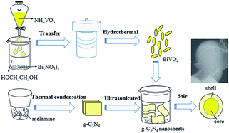
g-C3N4 was synthesized through thermal condensation.47 5 g of melamine were put into an aluminum crucible with a cover on and subsequently heated in a muffle furnace at a rate of 5 °C min−1 until the temperature reached 550 °C where it was maintained for 4 hours. After cooling down to the room temperature, the light-yellow g-C3N4 products were ground and collected.To prepare the g-C3N4 nano-sheets, 0.2 g g-C3N4 powder was ultra-sonicated in 1000 mL distilled water for 24 hours followed by centrifugation to remove the un-exfoliated g-C3N4, resulting in g-C3N4 nano-sheets dispersed solution. The concentration of the g-C3N4 nano-sheet suspension is about 0.07 g L−1.
2.2. Synthesis of BiVO4
BiVO4 was synthesized through a hydrothermal method.48 In this process, bismuth nitrate (Bi(NO3)3·5H2O) and ammonium vanadate (NH4VO3) were used as the bismuth and vanadate sources. 1.98 g Bi(NO3)3·5H2O were dissolved in 40 mL ethylene glycol, forming a homogeneous milk-white solution under magnetic stirring. Then, 0.98 g of NH4VO3 were dissolved in 40 mL hot water, forming an orange-yellow transparent solution. The above NH4VO3 solution was added into the Bi(NO3)3 solution dropwise under vigorous stirring and incubated for 30 min. The resulting solution was then transferred to 100 mL Teflon-lined stainless steel autoclave and maintained at 100 °C for 12 h. After cooling the reactor down to room temperature, the yellow precipitates were collected and washed three times with distilled water and ethyl alcohol. Finally, the products were dried at 80 °C in electric oven for 6 h and a yellowish BiVO4 powder was obtained.2.3. Synthesis of BiVO4@g-C3N4 core–shell composite photo-catalyst
BiVO4@g-C3N4 core–shell composite photo-catalysts were synthesized by vigorous-stirring chemisorption (Fig. 1). 0.2 g BiVO4 were added into measured amounts of g-C3N4 nano-sheets suspension (0.07 g L−1) followed by ultra-sonication for 60 minutes and stirring for 24 h. Various weight ratios of g-C3N4 to BiVO4@g-C3N4 (x wt%) (x = 1, 3, 5, 7, 10) were prepared by tuning the volume of g-C3N4 nano-sheets between 40 mL, 90 mL, 150 mL, 200 mL, and 300 mL, respectively.2.4. Characterization
The crystal structures and phase data for the prepared BiVO4@g-C3N4 composite samples were detected by X-ray diffraction (XRD) using a Rigaku D/MAX2500 PC diffractometer with Cu-Kα radiation and an operating voltage and current of 40 kV and 100 mA, respectively. The morphology of the core–shell BiVO4@g-C3N4 samples was investigated by scanning electron microscope (SEM) (Hitachi, S-4800) and transmission electron microscopy (TEM) (JEOL Ltd., JEM-2010). Energy dispersive X-ray spectroscopy (EDX) displayed the distribution of the composed elements. UV-vis light (UV-vis) diffuse reflectance spectra were recorded on a UV-vis spectrometer (Puxi, UV1901) with BaSO4 used as the reference, based on the data, the band-gap energy of the samples could be concluded. A similar trend occurs when calculating the band-gap energy (Eg) according to the follow formula:| (αhν)n = A(hν − Eg) |
2.5. Photocatalytic activity evaluation
The photocatalytic reaction of BiVO4@g-C3N4 composite photo-catalyst under visible light was carried out by photodegradation of RhB. RhB is a very stable dye and has been used widely in evaluating the performance of numerous photo-catalysts under visible light irradiation. The photocatalytic reactions were carried out in quartz tubes (Nanjing, Xujiang), with a 3 cm distance from the light source. Visible light was supplied by a 400 W halogen lamp with cut-off filters for λ ≥ 420 nm. 100 mg of the catalyst powder was dispersed into 50 mL of 10 mg L−1 RhB solution. The temperature of the reaction mixture was maintained at 25 ± 2 °C using a recirculating cooling water system. The suspension was stirred for 30 min in the dark to make ensure that the absorption–desorption equilibrium between the photo-catalyst and the RhB had been reached, at which point the light was turned on. 5 mL of the sample were taken out at constant time intervals during the reaction process over the course of 60 minutes. The samples were then centrifuged for 6 minutes at 10![[thin space (1/6-em)]](https://www.rsc.org/images/entities/char_2009.gif) 000 rpm to remove the photo-catalyst powder. The supernatant was analyzed by UV-vis (TU-1901, Puxi) spectroscopy and the absorbance (A) was used to determine the concentration of RhB according to the Beer–Lambert law. The degradation efficiency of RhB was calculated by the following formula:
000 rpm to remove the photo-catalyst powder. The supernatant was analyzed by UV-vis (TU-1901, Puxi) spectroscopy and the absorbance (A) was used to determine the concentration of RhB according to the Beer–Lambert law. The degradation efficiency of RhB was calculated by the following formula:where C0 represents the original concentration of RhB and C represents the concentration of RhB at time “t”.
3. Result and discussion
3.1. XRD
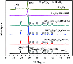
XRD analysis was applied to evaluate the crystal phase of BiVO4 and BiVO4@g-C3N4 composites. Fig. 2 shows the XRD patterns of g-C3N4, BiVO4, and BiVO4@g-C3N4 with different coated amounts of g-C3N4 nano-sheets. For the pure g-C3N4, it can be clearly seen that the peaks at 12.8° and 27.8° correspond to the (100) and (002) diffraction planes (JCPDS 87-1526), respectively, which are characteristic of graphitic materials and fit well with reported literatures.49 Where the (100) diffraction peak at 12.8° represents the in-plane structural packing motif of tri-s-triazine units, and the peak at 27.8° is indexed as (002) peak of the stacking of conjugated aromatic system, and the distance of interlayer spacing is 0.320 nm.50 The XRD pattern of g-C3N4 nano-sheet obtained by ultra-sonicated shows only one obvious peak of (002), and the (002) diffraction peak of g-C3N4 nano-sheet is wider and weaker, indicating the stacking of interlayer structure is broken and the exfoliated g-C3N4 nano-sheet is obtained.39,51 As for BiVO4, the observed peaks at 18.67°, 28.82°, 30.55°, 35.22°, 39.78°, 47.31°, 50.31°, 53.31° and 58.53° correspond to the (011), (121), (040), (002), (211), (042), (202), (161) and (123) crystal planes of m-BiVO4 (JCPDS 14-0688).17,48,52,53 The characteristic diffraction peaks were sharp, proving the better purity and crystallinity of BiVO4. However, for the BiVO4@g-C3N4 (x wt%) (x < 10) samples, only diffraction peaks of BiVO4 were observed with no evidence of the existence of g-C3N4. This is likely due to small amounts of g-C3N4 nano-sheets being coated as well as the low diffraction intensity22 of g-C3N4 in the composites. The existence of g-C3N4 can be shown through EDS, FT-IR and XPS, which is discussed later.3.2. SEM & TEM analysis
The morphology and structure of the as-synthesized photo-catalysts were characterized by both scanning electron microscopy (SEM) and transmission electron microscopy (TEM). As shown in Fig. 3(a), bulk g-C3N4 had a layered structure, and the average size was about 2–3 μm, while the g-C3N4 nano-sheets treated by ultrasonication were much looser (Fig. 3(b)). The BiVO4 precursor was a regular ellipsoid about 500 nm in diameter and 1–2 μm in length (Fig. 3(c)). For the BiVO4@g-C3N4 (7 wt%) composites seen in Fig. 3(d) and (e), the thinner g-C3N4 nano-sheets can be seen coated on the ellipsoid-like BiVO4, the core–shell structure enlarges the contact area between the BiVO4 and g-C3N4 nano-sheet, which benefits the transfer of photo-excited charge and enlarges the light absorption areas. More details about the core–shell structure will be discussed in the TEM images. The EDS analysis (shown in Fig. 3(f)) proves the existence of the elements Bi, V, O, C and N, which supports the existence of g-C3N4.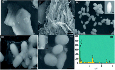 | ||
| Fig. 3 SEM images of (a) g-C3N4; (b) g-C3N4 nano-sheets; (c) BiVO4; (d) and (e) BiVO4@g-C3N4; (f) the EDS for BiVO4@g-C3N4 (7 wt%). | ||
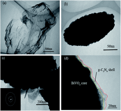
TEM characterization of the prepared samples was performed in order to further study the details of the morphology and microstructure of the pure g-C3N4, the BiVO4 and the BiVO4@g-C3N4 (Fig. 4). The g-C3N4 exfoliated by ultrasound had a thin nano-sheet morphology, just like the thin film with the soft edges, the wrinkled layer with some stacking layers represents the soft nanosheets (Fig. 4(a)). Fig. 4(b) shows that the pure BiVO4 was ellipsoid-like with tiny bulges on its rough surface, the average size is 500 nm in diameter. The TEM images of the BiVO4@g-C3N4 samples are shown in Fig. 4(c) and (d). The dark black area surrounded by a gray edge represents the BiVO4 core protected by the g-C3N4 nano-sheet shell. The thickness of g-C3N4 shell was about 7 nm (light-yellow lined areas). The obtained core–shell structure strengthens the tight contact between BiVO4 and g-C3N4 nano-sheets, differs from the point contact of the loaded composites, the surface contact of core@shell structure enlarges the contact area, more contact areas does help to strengthen the synergetic effect between the π-conjugated g-C3N4 and inner BiVO4. This not only benefits the area of light absorption, but also improves the chemical band interaction of BiVO4 and g-C3N4, enhancing the separation efficiency of photo-induced charge, with the higher photo-degradation efficiency, this will be studied in the following discussion. The SAED pattern of BiVO4 core indicates high crystallinity of BiVO4 and is in agreement with the XRD analysis.
3.3. FT-IR spectra analysis
FT-IR spectra were used to characterize the special chemical bands of the prepared samples. Fig. 5 shows the FT-IR spectra of g-C3N4, BiVO4 and BiVO4@g-C3N4 (7 wt%). For the pure BiVO4, the peak at 698 cm−1 represents the Bi–O bond while the 733 cm−1 stretching peak corresponds to ν3(VO4).54 Both of them are typical peaks of BiVO4.55 The peaks at around 1400 cm−1 can be attributed to the absorption of atmospheric carbon dioxide, while the peak at 1650 cm−1 is characteristic of residual water on the surface.53 The FT-IR spectra of g-C3N4 shows the molecular structure of the compound: there is a peak at 808 cm−1 that is attributed to the C–N hetero-cycle, there are bands at 1237 cm−1, 1315 cm−1, 1406 cm−1 representing the aromatic C–N stretching peaks, and a peak at 1640 cm−1 representing the C![[double bond, length as m-dash]](https://www.rsc.org/images/entities/char_e001.gif) N stretching. These peaks are consistent with those previously reported in literature.25 The FT-IR spectra of core–shell BiVO4@g-C3N4 shows both the typical stretching peaks of BiVO4 and g-C3N4. The bands of BiVO4 appear at 694 cm−1 and 731 cm−1 and are slightly red shifted when compared with pure BiVO4. Likewise, the peaks of g-C3N4 appear at their typical positions but with a slight red shift, as seen in the enlarged portion of the FT-IR spectra in Fig. 5(b). The band strengths are weakened in the composite photocatalyst, which indicates the increased stretching of the C–N, C
N stretching. These peaks are consistent with those previously reported in literature.25 The FT-IR spectra of core–shell BiVO4@g-C3N4 shows both the typical stretching peaks of BiVO4 and g-C3N4. The bands of BiVO4 appear at 694 cm−1 and 731 cm−1 and are slightly red shifted when compared with pure BiVO4. Likewise, the peaks of g-C3N4 appear at their typical positions but with a slight red shift, as seen in the enlarged portion of the FT-IR spectra in Fig. 5(b). The band strengths are weakened in the composite photocatalyst, which indicates the increased stretching of the C–N, C![[double bond, length as m-dash]](https://www.rsc.org/images/entities/char_e001.gif) N, Bi–O and V–O bonds and a more widely π-conjugated system appears between the g-C3N4 nano-sheets and BiVO4 core.40,56 The core–shell structure induced modified interactions between chemical bands, a covalent bond between g-C3N4 and BiVO4 was formed, which in turn resulted in an improvement in the transfer and separation efficiency of photo-induced charges and increased photo-catalytic degradation efficiency.
N, Bi–O and V–O bonds and a more widely π-conjugated system appears between the g-C3N4 nano-sheets and BiVO4 core.40,56 The core–shell structure induced modified interactions between chemical bands, a covalent bond between g-C3N4 and BiVO4 was formed, which in turn resulted in an improvement in the transfer and separation efficiency of photo-induced charges and increased photo-catalytic degradation efficiency.
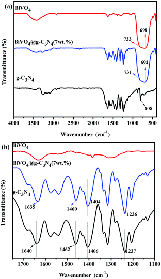 | ||
| Fig. 5 (a) FTIR spectra of the prepared g-C3N4, BiVO4 and BiVO4@g-C3N4 photo-catalysts; (b) partial enlarged details of FTIR spectra for g-C3N4, BiVO4 and BiVO4@g-C3N4 between 1100–1750 cm−1. | ||
3.4. UV-vis analysis
UV-vis (ultraviolet-visible) absorption spectra were acquired in order to study the optical properties of the prepared samples and to further prove their photo-catalytic activity under visible light. The UV-vis of g-C3N4, BiVO4 and BiVO4@g-C3N4 are shown in Fig. 6(a). For pure g-C3N4, the edge of the absorption spectra is at about 470 nm and shows strong absorption both in the ultraviolet and partial visible regions. The UV-vis absorption spectra of the g-C3N4 nano-sheets shows a blue shift of about 10–20 nm in the absorption edge. As for pure BiVO4, a stronger and wider absorbency is seen in visible light range. For the BiVO4@g-C3N4 composites photo-catalyst, the absorption edge is red shifted significantly compared to g-C3N4, and wider light absorption is seen in the visible region. This indicates that BiVO4@g-C3N4 may be able to absorb more light to generate electron–hole pairs. However, there was no obvious change in absorbance range between the BiVO4 and the composite photo-catalysts with differing g-C3N4 coating amounts. BiVO4@g-C3N4 is a direct-gap semiconductor and uses a value of n = 2. According to the transformed Kubelka–Munk function, the band-gap energy can be estimated by the intercept of the tangent to the plot of (αhν)2 vs. (hν). The results obtained from these plots are shown in Fig. 6(b). The band-gap energy of g-C3N4 was found to be 2.78 eV, whereas g-C3N4 nano-sheet has a larger energy of 2.82 eV which might the effect of quantum confinement between the tiny nano-sheets and the larger light absorption area of the nano-sheet. The calculated band-gap energies of BiVO4 and BiVO4@g-C3N4 (3, 5, 7, 10 wt%) are both 2.45 eV, because of the little change of the edge of the absorption spectra among the samples. The effects of core@shell structure on composites photo-catalyst activity will be discussed further.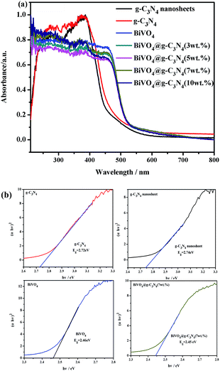 | ||
| Fig. 6 (a) UV-vis diffuse reflectance spectra of prepared photo-catalysts; (b) plot of (αhν)2 vs. energy (hν) and band-gap energy of the g-C3N4, g-C3N4 nano-sheet, BiVO4, BiVO4@g-C3N4 samples. | ||
3.5. XPS spectra analysis
X-ray photoelectron spectroscopy (XPS) was performed to detect the surface chemical composition and chemical states of the prepared BiVO4 and BiVO4@g-C3N4 (7 wt%) samples. Fig. 7(a) shows the survey scan XPS spectrum of the two samples. Bi 4f, V 2p, O 1s, as well as C 1s, N 1s for the composite photo-catalyst are seen, proving that the photo-catalyst included all of the elemental components, which is in agreement with the EDS analysis results. In the core–shell BiVO4@g-C3N4, the XPS spectra showed C 1s (Fig. 7(b)), and the binding energies of 284.8 eV and 288.05 eV are representative of the absorbed carbon on the surface and the C atom of sp2-hybridized N–C![[double bond, length as m-dash]](https://www.rsc.org/images/entities/char_e001.gif) N bond,57 respectively. Three peaks in the N 1s binding energy area are clearly seen (Fig. 7(c)). The peak at 397.43 eV is due to C
N bond,57 respectively. Three peaks in the N 1s binding energy area are clearly seen (Fig. 7(c)). The peak at 397.43 eV is due to C![[double bond, length as m-dash]](https://www.rsc.org/images/entities/char_e001.gif) N–C bonds, and the other two peaks at about 398.92 eV and 401.11 eV attributed to the N atoms of N–(C)3 bond and H–N–C bond,25 respectively. For the composite photo-catalyst, the binding energies of these C 1s and N 1s peaks are typical in g-C3N4. In order to further study the interaction between the chemical states and core–shell structure, the XPS spectra of Bi, V and O were obtained and are depicted in Fig. 7(d)–(f). For bismuth, the typical peaks at 158.78 eV and 164.08 eV were the binding energies of Bi 4f7/2 and Bi 4f5/2, respectively, which indicates the existence of Bi3+ in BiVO4. As for BiVO4@g-C3N4 (7 wt%), the binding energy of Bi3+ was found to be slightly increased (158.81 eV and 164.25 eV). For V 2p orbital, the binding energy peaks at 523.8 eV and 516.43 eV of V 2p1/2 and V 2p3/2 represent the V5+ in BiVO4. Similarity, the peaks of V 2p1/2 and V 2p3/2 for BiVO4@g-C3N4 (7 wt%) shift to higher binding energy at 524.16 eV and 516.75 eV (Fig. 7(e)). The XPS spectra of O 1s show three main peaks: the peak at 529.42 eV can be assigned to the lattice oxygen in BiVO4, while the peaks at 530.14 eV and 532.25 eV are signals from hydroxyl groups and absorbed water on the surface of the sample. In addition, three forms of oxygen are found in the composite, the binding energies of O 1s of BiVO4@g-C3N4 (7 wt%) are larger than those found in pure BiVO4. The interaction of shell g-C3N4 nano-sheets and core BiVO4 is confirmed by these increased binding energies,40 the inner interaction between shell and core induces to the shift of Bi 4f, V 2p and O 1s orbitals.58 The positive shift of binding energy means the increase of the electron density around the Bi, V, O, indicating a stronger chemical band of core–shell photo-catalyst,45 not the simple physical mixture of BiVO4 and g-C3N4. The π-conjugated shell g-C3N4 nano-sheets strengthens the chemical bonds of BiVO4. The synergetic effect between the core@shell structure forms a wider π-conjugated system, the chemical interaction is strong enough to promote better separation of photo-excited electron–hole pairs, also the larger contact area does help to transfer the separated charge, effectively increasing the photo-catalysis degradation efficiency. This results support the conclusion of the FT-IR analysis.
N–C bonds, and the other two peaks at about 398.92 eV and 401.11 eV attributed to the N atoms of N–(C)3 bond and H–N–C bond,25 respectively. For the composite photo-catalyst, the binding energies of these C 1s and N 1s peaks are typical in g-C3N4. In order to further study the interaction between the chemical states and core–shell structure, the XPS spectra of Bi, V and O were obtained and are depicted in Fig. 7(d)–(f). For bismuth, the typical peaks at 158.78 eV and 164.08 eV were the binding energies of Bi 4f7/2 and Bi 4f5/2, respectively, which indicates the existence of Bi3+ in BiVO4. As for BiVO4@g-C3N4 (7 wt%), the binding energy of Bi3+ was found to be slightly increased (158.81 eV and 164.25 eV). For V 2p orbital, the binding energy peaks at 523.8 eV and 516.43 eV of V 2p1/2 and V 2p3/2 represent the V5+ in BiVO4. Similarity, the peaks of V 2p1/2 and V 2p3/2 for BiVO4@g-C3N4 (7 wt%) shift to higher binding energy at 524.16 eV and 516.75 eV (Fig. 7(e)). The XPS spectra of O 1s show three main peaks: the peak at 529.42 eV can be assigned to the lattice oxygen in BiVO4, while the peaks at 530.14 eV and 532.25 eV are signals from hydroxyl groups and absorbed water on the surface of the sample. In addition, three forms of oxygen are found in the composite, the binding energies of O 1s of BiVO4@g-C3N4 (7 wt%) are larger than those found in pure BiVO4. The interaction of shell g-C3N4 nano-sheets and core BiVO4 is confirmed by these increased binding energies,40 the inner interaction between shell and core induces to the shift of Bi 4f, V 2p and O 1s orbitals.58 The positive shift of binding energy means the increase of the electron density around the Bi, V, O, indicating a stronger chemical band of core–shell photo-catalyst,45 not the simple physical mixture of BiVO4 and g-C3N4. The π-conjugated shell g-C3N4 nano-sheets strengthens the chemical bonds of BiVO4. The synergetic effect between the core@shell structure forms a wider π-conjugated system, the chemical interaction is strong enough to promote better separation of photo-excited electron–hole pairs, also the larger contact area does help to transfer the separated charge, effectively increasing the photo-catalysis degradation efficiency. This results support the conclusion of the FT-IR analysis.
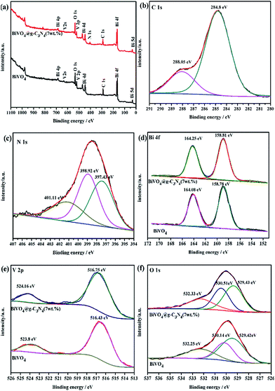 | ||
| Fig. 7 (a) All XPS spectra of BiVO4 and BiVO4@g-C3N4; XPS spectra of BiVO4@g-C3N4 (b) C 1s; (c) N 1s; XPS spectra of BiVO4 and BiVO4@g-C3N4 (d) Bi 4f; (e) V 2p; (f) O 1s. | ||
3.6. Photocatalytic activity evaluation
Rhodamine B was employed in order to investigate the photocatalytic degradation rate of the BiVO4@g-C3N4 samples under visible light radiation (λ ≥ 420 nm). A blank experiment without any photocatalyst powder was carried out in order to quantify background degradation of RhB. The results of all experiments under irradiation for 60 min are shown in Fig. 8(a), including the blank and dark experiments as well as the RhB photo-degradation by g-C3N4, BiVO4, and BiVO4@g-C3N4 (x wt%). The highest degradation activity is seen when the composite contains 7% g-C3N4. An increase in activity is seen as the g-C3N4 concentration increases up to 7%, but a decrease is seen beyond this concentration at 10%. The BiVO4@g-C3N4 (7 wt%) degraded about 90% of the RhB, a result that is 9 times greater than pure BiVO4 (9%) and 1.3 times greater than pure g-C3N4 nano-sheets. When the g-C3N4 content was increased to 10%, the degradation efficiency of BiVO4@g-C3N4 (10 wt%) decreased to 80%. The kinetic constants for the different compositions of BiVO4@g-C3N4 were calculated (Fig. 8(b)) by assuming that the degradation rate fit the pseudo-first-order reaction model (ln(C0/Ct) = kt). When the g-C3N4 amounts were 1%, 3%, 5%, 7%, 10%, the values of k were 0.00435 min−1, 0.00761 min−1, 0.00996 min−1, 0.03971 min−1 and 0.02661 min−1, respectively. The coated amount of g-C3N4 nano-sheets had a great effect on the photocatalytic activity. When the g-C3N4 nano-sheet content was less than 7 wt%, the contact area of the core–shell structure was not large enough to promote photo-degradation. However, excessive coating with g-C3N4 nano-sheet might lead to resistance for the separation of electron–hole pairs and transfer. With the optimal coating amount of 7%, the larger light absorption area and π-conjugation promoted the best photocatalytic degradation efficiency, which agrees with the FT-IR and XPS results shown previously.To further prove the effectiveness of the composite photocatalyst, a comparison of BiVO4@g-C3N4 (7 wt%) and mechanically mixed BiVO4/g-C3N4 (7 wt%) was performed and the results are shown in Fig. 8(c). The M-BiVO4/g-C3N4 (7 wt%) had a similar photocatalytic performance as pure g-C3N4 nano-sheets, and a lower performance than BiVO4@g-C3N4 (7 wt%). This result shows that the core–shell structure plays an important role in promoting photocatalytic activity. Fig. 8(d) shows the whole spectra scan of RhB during the photocatalytic degradation progress using BiVO4@g-C3N4 (7 wt%), the descending peaks of RhB for other photocatalyst samples are shown in the ESI (Fig. S1†), the inner line of Fig. 8(d) is the wavelength shift of the RhB spectra under the photo irradiation of Fig. 8(d). As the symbols in red shows, the major absorption peaks of the RhB showed a blue shift from 553 nm to 497 nm gradually, the blue shift of 56 nm indicating that the RhB was mineralized by de-ethylation. De-ethylation of RhB (N,N,N′,N′-tetra-ethylated rhodamine molecule, λmax = 554 nm) has the characteristic peak shifted to the blue region, rhodamine, λmax = 497 nm, the conjugated structure of stable RhB was destroyed59,60 photocatalytically.
3.7. Trapping experiment & repeating experiment
It is well known that photo-excited electrons and holes have strong reduction and oxidation properties. This allows them to react with absorbed O2 on the catalyst surface and generate reactive species during the photo-degradation process, such as ·O2−, h+ and ·OH. In order to investigate the photocatalytic mechanism of BiVO4@g-C3N4, a trapping experiment was designed to detect and quantify these reactive species. Benzoquinone (BQ) was added to the reaction system as a scavenger of ·O2−, isopropanol (IPA) was added to trap the ·OH radicals, and the ethylene diamine tetra-acetic acid disodium salt (EDTA-2Na) was used as a h+ scavenger. The trapping experiments were maintained under the same reaction conditions as the photocatalytic activity evaluation. As seen in Fig. 9(a), the presence of IPA had little effect on the degradation rate of RhB, indicating that the ·OH radical was not the main reactive species. The degradation rate was greatly suppressed with the addition of EDTA-2Na, indicating that h+ was an important species in the degradation of RhB. O2− also played an assistant role in RhB degradation. These results provide the framework for a possible photo-degradation mechanism.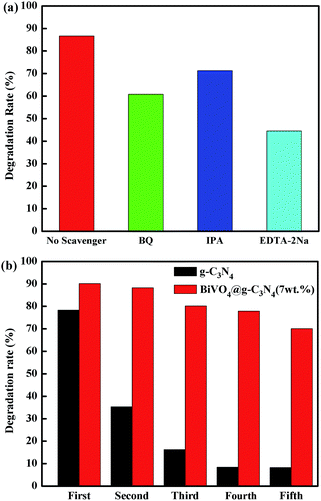 | ||
| Fig. 9 (a) The comparison of degradation rate with addition of different scavengers; (b) five cycle running of photo-degradation RhB over g-C3N4 and BiVO4@g-C3N4 (7 wt%). | ||
As a high-performance photo-catalyst, it is important to evaluate the stability of prepared core–shell BiVO4@g-C3N4 composite under visible light irradiation. In order to better study the stability and recyclability of the composite photo-catalyst, a repeating experiment of photo-degradation of RhB was carried out for five cycles. Fig. 9(b) shows the experimental degradation rate of the sample after five cycles. The pure g-C3N4 sample showed a great deal of instability, with the photo-degradation efficiency decreasing from 78% to 8%. Conversely, the BiVO4@g-C3N4 (7 wt%) photocatalyst was quite stable, and the degradation rate only decreased to 75% after five recycling runs. The core–shell BiVO4@g-C3N4 composite photo-catalyst demonstrated pretty good stability and reusability. The core–shell structure promoted chemical band interaction and stability of the composite photo-catalyst while enlarging the reaction contact area.
3.8. Photoluminescence (PL) spectra & photocurrent & EIS analysis
Photoluminescence emission spectra were obtained in order to further study the separation efficiency of electron–hole pairs. Higher intensities in the emission spectra of the sample indicate quicker recombination of photo-generated charges, thus leading to reduced photo-catalytic activity. The PL spectra of g-C3N4, BiVO4 and BiVO4@g-C3N4 under excitation at 320 nm are shown in Fig. 10(a). It can be clearly seen that the pure BiVO4 produced strong emission peaks around 520 nm.61 The relative intensity of BiVO4 was much greater than that of BiVO4@g-C3N4, and the PL intensity of g-C3N4 was also greater, indicating that coating with g-C3N4 nano-sheets played an important role in suppressing the recombination of electrons and holes. The core–shell structure resulted in an improvement in the separation efficiency of photo-generated charges. Fig. 10(b) shows a magnified view of the PL spectra of BiVO4@g-C3N4 (x wt%) (x = 3, 5, 7, 10). With increasing g-C3N4 content, the intensities of PL decrease until the content reaches 7%, after which the intensity increases. This may be due to an excess in g-C3N4 nano-sheets on the surface resulting in a gradual disappearance of the π-conjugated synergetic effect. These results are in agreement with the photo-catalytic activity results.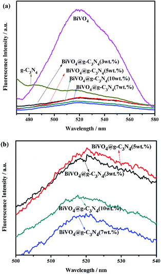 | ||
| Fig. 10 (a) Photoluminescence spectra of as-prepared g-C3N4, BiVO4, BiVO4@g-C3N4; (b) partial enlarged PL spectra of BiVO4@g-C3N4 with different amounts of g-C3N4 nano-sheets. | ||
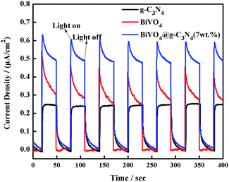
In order to provide more evidence of photoelectron and hole separation, a transient photocurrent response experiment was performed under visible light irradiation every 30 seconds. A higher photocurrent response value indicates lower recombination and more efficient separation of electron–hole pairs.62 As the results in Fig. 11 show, the semiconductor electrodes modified by the BiVO4, g-C3N4 and BiVO4@g-C3N4 samples show quick photocurrent response under the light irradiation, and decrease to zero immediately as soon as the light off. The BiVO4@g-C3N4 composite conducts the most photocurrent when compared with both pure BiVO4 and g-C3N4. Namely, more electron–hole pairs can be separated efficiently over the BiVO4@g-C3N4 sample, and the longer lifetime of the photo-excited charge carrier than that of pure BiVO4, g-C3N4. In this case, the core–shell structure resulted in a larger contact area which contributed to a higher photocurrent response and inhibited the recombination rate of photo-excited reactive electrons and holes.
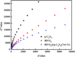
Electrochemical impedance spectroscopy (EIS) of pure g-C3N4, BiVO4 and BiVO4@g-C3N4 was performed in order to investigate the charge transfer resistance and assess the separation efficiency of electron–hole pairs, which is a crucial factor for photocatalytic degradation. In the Nyquist diagram of EIS, a smaller radius is evidence of smaller charge transfer resistance and a faster charge transfer rate.63 Fig. 12 shows that the arc radius of BiVO4@g-C3N4 (7 wt%) is the smallest among the three samples. The core–shell structure formed between BiVO4 and the g-C3N4 nano-sheets changed the chemical bands and altered the resistance on the electrode surface, resulting in higher separation efficiency and a faster transfer rate of photo-generated charges. As the widely conjugated system developed, just as the FT-IR and XPS analysis, the interaction between g-C3N4 nano-sheets shell and BiVO4 core can provide an effective path for the transfer of photo-induced charges. These datas also support the results from the photocatalytic activity, PL, and photocurrent results.
3.9. The proposed mechanism of photocatalytic degradation
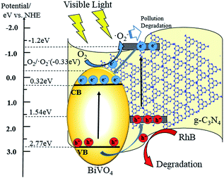
Based on the analysis and characterization of the experimental results above, a possible photocatalytic mechanism for core–shell BiVO4@g-C3N4 is proposed and discussed below. The layered g-C3N4 nano-sheets coated on the ellipsoid-like BiVO4 provide a larger contact area and interface between the core and shell, resulting in strengthening of the π-conjugated system and promotion of the separation of photo-generated electron–hole pairs. This enables a higher photo-degradation efficiency under light irradiation. Proper band gap position of the photo-catalyst is one of the key factors to promote separation of electron–hole pairs and is a result of the composite's properties. According to the data from the UV-vis experiments, the band-gap energy of BiVO4 is 2.46 eV (Fig. 5(b)). The band gap edge positions of the conduction band and valence band can be calculated by the formulas:| ECB = X − Ee − 0.5Eg, EVB = ECB + Eg |
4. Conclusions
Ellipsoid-like BiVO4 and core–shell structured BiVO4@g-C3N4 were successfully synthesized through a hydrothermal and ultra-sonicated-chemisorption method. Ellipsoid-like BiVO4 was prepared through the addition of ethylene glycol. The performance of the composite photo-catalyst was accessed by evaluating its ability to degrade RhB pollution in water. The highest photo-degradation efficiency occurred when the content of g-C3N4 nano-sheet was 7% and was 9 times greater than that of pure BiVO4. In addition, the core–shell BiVO4@g-C3N4 showed high stability after five cycles of light irradiation. The stable core–shell structure of the composite photo-catalyst not only enlarged the contact area, but also strengthened the interaction of chemical bands, effectively enhancing the π-conjugation. This resulted in efficient separation of the photo-excited electron–hole pairs and a high rate of photo-degradation of RhB (90% degradation in 60 min). This promising novel core–shell composite photo-catalyst provides an exciting area for further application and study.Acknowledgements
This work was funded by the National Natural Science Foundation of China (grant No. 21476161), Key Program of Natural Science of Hebei Province (B2016209375), Hebei Provincial Foundation for International Cooperation (No. 15391403D) and National Science and Engineering Research Council of Canada (Discovery).Notes and references
- A. Fujishima and K. Honda, Nature, 1972, 238, 37–38 CrossRef CAS PubMed.
- H. Tong, S. Ouyang, Y. Bi, N. Umezawa, M. Oshikiri and J. Ye, Adv. Mater., 2012, 24, 229–251 CrossRef CAS PubMed.
- C. McCullagh, N. Skillen, M. Adams and P. K. J. Robertson, J. Chem. Technol. Biotechnol., 2011, 86, 1002–1017 CrossRef CAS.
- D. Chatterjee and S. Dasgupta, J. Photochem. Photobiol., C, 2005, 6, 186–205 CrossRef CAS.
- X. Chen, Y. Dai and X. Wang, J. Alloys Compd., 2015, 649, 910–932 CrossRef CAS.
- M. Pelaez, N. T. Nolan, S. C. Pillai, M. K. Seery, P. Falaras, A. G. Kontos, P. S. M. Dunlop, J. W. J. Hamilton, J. A. Byrne, K. O'Shea, M. H. Entezari and D. D. Dionysiou, Appl. Catal., B, 2012, 125, 331–349 CrossRef CAS.
- M. Ni, M. K. H. Leung, D. Y. C. Leung and K. Sumathy, Renewable Sustainable Energy Rev., 2007, 11, 401–425 CrossRef CAS.
- Z. Yi, J. Ye, N. Kikugawa, T. Kako, S. Ouyang, H. Stuart-Williams, H. Yang, J. Cao, W. Luo, Z. Li, Y. Liu and R. L. Withers, Nat. Mater., 2010, 9, 559–564 CrossRef CAS PubMed.
- X. Zhang, X. B. Wang, L. W. Wang, W. K. Wang, L. L. Long, W. W. Li and H. Q. Yu, ACS Appl. Mater. Interfaces, 2014, 6, 7766–7772 CAS.
- J. Xia, S. Yin, H. Li, H. Xu, Y. Yan and Q. Zhang, Langmuir, 2011, 27, 1200–1206 CrossRef CAS PubMed.
- J. Zhang, F. Shi, J. Lin, D. Chen, J. Gao, Z. Huang, X. Ding and C. Tang, Chem. Mater., 2008, 20, 2937–2941 CrossRef CAS.
- H. Huang, X. Han, X. Li, S. Wang, P. K. Chu and Y. Zhang, ACS Appl. Mater. Interfaces, 2015, 7, 482–492 CAS.
- H. Huang, K. Xiao, Y. He, T. Zhang, F. Dong, X. Du and Y. Zhang, Appl. Catal., B, 2016, 199, 75–86 CrossRef CAS.
- S. Guo, X. Li, H. Wang, F. Dong and Z. Wu, J. Colloid Interface Sci., 2012, 369, 373–380 CrossRef CAS PubMed.
- D. Sánchez-Martínez, D. B. Hernández-Uresti, L. M. Torres-Martinez and S. Mejia-Rosales, Res. Chem. Intermed., 2015, 41, 8839–8854 CrossRef.
- B.-X. Lei, L.-L. Zeng, P. Zhang, Z.-F. Sun, W. Sun and X.-X. Zhang, Adv. Powder Technol., 2014, 25, 946–951 CrossRef CAS.
- T. Saison, N. Chemin, C. Chanéac, O. Durupthy, L. Mariey, F. Maugé, V. Brezová and J.-P. Jolivet, J. Phys. Chem. C, 2015, 119, 12967–12977 CAS.
- O. F. Lopes, K. T. G. Carvalho, A. E. Nogueira, W. Avansi and C. Ribeiro, Appl. Catal., B, 2016, 188, 87–97 CrossRef CAS.
- S. Obregón, A. Caballero and G. Colón, Appl. Catal., B, 2012, 117–118, 59–66 CrossRef.
- W. Wang, X. Huang, S. Wu, Y. Zhou, L. Wang, H. Shi, Y. Liang and B. Zou, Appl. Catal., B, 2013, 134–135, 293–301 CrossRef CAS.
- C. Li, P. Zhang, R. Lv, J. Lu, T. Wang, S. Wang, H. Wang and J. Gong, Small, 2013, 9, 3951–3956 CrossRef CAS PubMed.
- S. Dong, Y. Cui, Y. Wang, Y. Li, L. Hu, J. Sun and J. Sun, Chem. Eng. J., 2014, 249, 102–110 CrossRef CAS.
- M. L. Guan, D. K. Ma, S. W. Hu, Y. J. Chen and S. M. Huang, Inorg. Chem., 2011, 50, 800–805 CrossRef CAS PubMed.
- W. Zhao, Y. Liu, Z. Wei, S. Yang, H. He and C. Sun, Appl. Catal., B, 2016, 185, 242–252 CrossRef CAS.
- X.-S. Zhang, J.-Y. Hu and H. Jiang, Chem. Eng. J., 2014, 256, 230–237 CrossRef CAS.
- T. Zhu, Y. Song, H. Ji, Y. Xu, Y. Song, J. Xia, S. Yin, Y. Li, H. Xu, Q. Zhang and H. Li, Chem. Eng. J., 2015, 271, 96–105 CrossRef CAS.
- X. Wang, K. Maeda, A. Thomas, K. Takanabe, G. Xin, J. M. Carlsson, K. Domen and M. Antonietti, Nat. Mater., 2009, 8, 76–80 CrossRef CAS PubMed.
- H. Yan and H. Yang, J. Alloys Compd., 2011, 509, L26–L29 CrossRef CAS.
- K. Sridharan, E. Jang and T. J. Park, Appl. Catal., B, 2013, 142–143, 718–728 CrossRef CAS.
- L. Ge, F. Zuo, J. Liu, Q. Ma, C. Wang, D. Sun, L. Bartels and P. Feng, J. Phys. Chem. C, 2012, 116, 13708–13714 CAS.
- X. Dai, M. Xie, S. Meng, X. Fu and S. Chen, Appl. Catal., B, 2014, 158–159, 382–390 CrossRef CAS.
- H. Xu, J. Yan, Y. Xu, Y. Song, H. Li, J. Xia, C. Huang and H. Wan, Appl. Catal., B, 2013, 129, 182–193 CrossRef CAS.
- H. Shi, C. Zhang and C. Zhou, RSC Adv., 2015, 5, 50146–50154 RSC.
- N. Tian, H. Huang, C. Liu, F. Dong, T. Zhang, X. Du, S. Yua and Y. Zhang, J. Mater. Chem. A, 2015, 3, 17120–17129 CAS.
- L. Ge, C. Han and J. Liu, Appl. Catal., B, 2011, 108–109, 100–107 CrossRef CAS.
- L. Liu, Y. Qi, J. Lu, S. Lin, W. An, J. Hu, Y. Liang and W. Cui, RSC Adv., 2015, 9, 99339–99346 RSC.
- C. Liu, H. Huang, X. Du, T. Zhang, N. Tian, Y. Guo and Y. Zhang, J. Phys. Chem. C, 2015, 119, 17156–17165 CAS.
- P. Niu, L. Zhang, G. Liu and H.-M. Cheng, Adv. Funct. Mater., 2012, 22, 4763–4770 CrossRef CAS.
- L. Liu, Y. Qi, J. Lu, S. Lin, W. An, Y. Liang and W. Cui, Appl. Catal., B, 2016, 183, 133–141 CrossRef CAS.
- S. Kumar, A. Baruah, S. Tonda, B. Kumar, V. Shanker and B. Sreedhar, Nanoscale, 2014, 6, 4830–4842 RSC.
- N. Tian, H. Huang, Y. He, Y. Guo, T. Zhang and Y. Zhang, Dalton Trans., 2015, 44, 4297–4307 RSC.
- H. J. Kong, D. H. Won, J. Kim and S. I. Woo, Chem. Mater., 2016, 28, 1318–1324 CrossRef CAS.
- Y. Ji, J. Cao, L. Jiang, Y. Zhang and Z. Yi, J. Alloys Compd., 2014, 590, 9–14 CrossRef CAS.
- C. Li, S. Wang, T. Wang, Y. Wei, P. Zhang and J. Gong, Small, 2014, 10, 2783–2790 CrossRef CAS PubMed.
- M. Ou, Q. Zhong and S. Zhang, J. Sol-Gel Sci. Technol., 2014, 72, 443–454 CrossRef CAS.
- Z. Li, M. Li, Z. Bian, Y. Kathiraser and S. Kawi, Appl. Catal., B, 2016, 188, 324–341 CrossRef CAS.
- S. W. Hu, L. W. Yang, Y. Tian, X. L. Wei, J. W. Ding, J. X. Zhong and P. K. Chu, Appl. Catal., B, 2015, 163, 611–622 CrossRef CAS.
- M. Ge, L. Liu, W. Chen and Z. Zhou, CrystEngComm, 2012, 14, 1038–1044 RSC.
- L. Ge, C. Han, J. Liu and Y. Li, Appl. Catal., A, 2011, 409–410, 215–222 CrossRef CAS.
- G. Liao, S. Chen, X. Quan, H. Yu and H. Zhao, J. Mater. Chem., 2012, 22, 2721–2726 RSC.
- X. Zhang, X. Xie, H. Wang, J. Zhang, B. Pan and Y. Xie, J. Am. Chem. Soc., 2013, 135, 18–21 CrossRef CAS PubMed.
- H. Li, K. Yu, X. Lei, B. Guo, H. Fu and Z. Zhu, J. Phys. Chem. C, 2015, 119, 22681–22689 CAS.
- J. Liu, H. Wang, S. Wang and H. Yan, Mater. Sci. Eng., B, 2003, 104, 36–39 CrossRef.
- M. Yang and X. Jin, J. Wuhan Univ. Technol., Mater. Sci. Ed., 2015, 30, 217–222 CrossRef CAS.
- M. Gotić, S. Musić, M. Ivanda, M. Šoufek and S. Popović, J. Mol. Struct., 2005, 744–747, 535–540 CrossRef.
- Y. Wang, R. Shi, J. Lin and Y. Zhu, Energy Environ. Sci., 2011, 4, 2922 CAS.
- S. C. Yan, Z. S. Li and Z. G. Zou, Langmuir, 2010, 26, 3894–3901 CrossRef CAS PubMed.
- S. Wang, D. Li, C. Sun, S. Yang, Y. Guan and H. He, Appl. Catal., B, 2014, 144, 885–892 CrossRef CAS.
- T. Wu, G. Liu and J. Zhao, J. Phys. Chem. B, 1998, 102, 5845–5851 CrossRef CAS.
- M. Yan, Y. Wu, Y. Yan, X. Yan, F. Zhu, Y. Hua and W. Shi, ACS Sustainable Chem. Eng., 2016, 4, 757–766 CrossRef CAS.
- D. K. Ma, M. L. Guan, S. S. Liu, Y. Q. Zhang, C. W. Zhang, Y. X. He and S. M. Huang, Dalton Trans., 2012, 41, 5581–5586 RSC.
- Y. Xu, H. Xu, L. Wang, J. Yan, H. Li, Y. Song, L. Huang and G. Cai, Dalton Trans., 2013, 42, 7604–7613 RSC.
- J. Kim, S. Byun, A. J. Smith, J. Yu and J. Huang, J. Phys. Chem. Lett., 2013, 4, 1227–1232 CrossRef CAS PubMed.
- J. Zhang, F. Ren, M. Deng and Y. Wang, Phys. Chem. Chem. Phys., 2015, 17, 10218–10226 RSC.
- J. Kim, C. W. Lee and W. Choi, Environ. Sci. Technol., 2010, 44, 6849–6854 CrossRef CAS PubMed.
Footnote |
| † Electronic supplementary information (ESI) available. See DOI: 10.1039/c6ra27766g |
| This journal is © The Royal Society of Chemistry 2017 |

