 Open Access Article
Creative Commons Attribution 3.0 Unported Licence
A ternary composite with manganese dioxide nanorods and graphene nanoribbons embedded in a polyaniline matrix for high-performance supercapacitors†
Tong Wua,
Chaonan Wangb,
Yao Moa,
Xinran Wanga,
Jinchen Fan *a,
Qunjie Xu*a and
Yulin Min*a
aShanghai Key Laboratory of Materials Protection and Advanced Materials in Electric Power, College of Environmental and Chemical Engineering, Shanghai University of Electric Power, Shanghai 200090, People's Republic of China. E-mail: Jinchen.fan@shiep.edu.cn; xuqunjie@shiep.edu.cn; minyulin@shiep.edu.cn; Fax: +86 21 35303544; Tel: +86 21 35303544
bCollege of Materials Science and Engineering, Guizhou Minzu University, Guiyang 550025, People's Republic of China
First published on 3rd July 2017
Abstract
A new ternary composite of manganese dioxide (MnO2), polyaniline (PANI) and graphene nanoribbons (GNRs) has been fabricated through a two-step polymerization process. With manganese dioxide nanorods and graphene nanoribbons embedded in the PANI matrix, the MnO2/GNRs/PANI ternary composites with 3-dimensional porous structures exhibited higher specific capacitance and better charge–discharge cycling performance than that of MnO2 and MnO2/GNRs binary composites in supercapacitors. The specific capacitance of the MnO2/PANI/GNRs ternary composite can be achieved at 472 F g−1. After 5000 cycles, the specific capacitance with 79.7% of the initial capacitance can be preserved. The enhanced specific capacitance and cycle life implies the structural stability of MnO2/GNRs/PANI ternary composites and the synergistic effect between MnO2, GNRs and PANI.
1. Introduction
Supercapacitors, also called ultracapacitors, have attracted considerable attention, owing to their high power density, long-cycle performance, optimal operational safety and rapid charge–discharge rates.1 In general, supercapacitors can be classified into two types depending on the charge storage mechanism and the corresponding active materials were used. Electrical double-layer capacitances (EDLCs), which store charges by reversible ion absorption between the electrode and electrolyte interface, mostly use carbon materials with high accessible surface area.2,3 Conventional carbon materials such as activated carbon, carbon nanotubes and carbon fiber usually exhibit good stability due to their special structures and large surface area.4–7 Nevertheless, their specific capacitance is limited due to the low theoretical capacity derived from EDLCs.8–10 The other type, known as pseudocapacitors, is based on redox reactions that occur largely on material surfaces to store charges.11,12 Typical pseudocapacitive materials include transition metal oxides, such as RuO2, MnO2, NiO,13,14 MoS2 (ref. 15) and conducting polymers like polyaniline (PANI), polypyrrole, and polythiophene.16–18 However, they usually display poor cycle performance with structural deformation during the charge and discharge processes.19 Undoubtedly, the capacitive performance of supercapacitors depend strongly on the performance of the electrode materials including their structures, surface area, conductivity and electrochemical stability.20 Therefore, increasing interest has been focused on the development of novel composites to enhance its capacitive performance.21Graphene nanoribbons (GNRs), thin elongated strips of graphene with a high length-to-width ratio and straight edges, can be successfully synthesized via longitudinal unzipping of MWCNTs by a chemical oxidation route. In recent years, GNRs-based materials have been extensively studied due to the high available surface area, extraordinary mechanical strength and outstanding electrical conductivity.22–24 The excellent electronic properties make them attractive especially as supporting materials for the fabrication of composites, and as so far, it has been studied in a wide range of applications such as batteries, supercapacitors and fuel cells.25–28
Nowadays, great interests are shown by researches on pseudocapacitance materials with excellent electrochemical characteristics such as metal oxides and conducting polymers. Among the metal oxides electrode materials, MnO2 has been studied extensively because of its advantages of low cost, natural abundance, environmental safety and high theoretical specific capacitance. However, the capacitance of MnO2 is limited by its poor electrical conductivity, which hinders the practical application in supercapacitors. On the other hand, among different kind of conducting polymers, PANI have been widely studied due to their controllable electrical conductivity and environmental stability. However, the drawbacks of the PANI electrode is also obvious, that is, a serious problem of typical volumetric swelling and shrinking happens during the charge–discharge process, which severely influence the cycle performance, limiting its practical usage in supercapacitors.
In recent years, binary or ternary composites of carbon materials, conducting polymers and metal oxides have been investigated to make full use of their advantages and overcome their disadvantages of each component. For example, multi-walled carbon nanotube/PANI/MnO2 ternary coaxial nanostructures,29 graphene/MnO2/PANI ternary composite,30 manganese ferrite/graphene/PANI nanostructure31 have been prepared to further enhance its capacitive performance. These researches have shown that it is an effective way by immobilizing carbon materials with pseudocapacitive conducting polymers and metal oxides. Because of the unique synergistic effects between carbon materials and pseudocapacitance materials may greatly improve the electrochemical properties of the hybrid composite.
In this paper, we report unique MnO2/GNRs/PANI ternary composites with GNRs and MnO2 nanorods embedded in PANI matrix. The introduction of PANI can not only prohibit the stacking of GNRs, but also fastens all of them directly interconnected with MnO2 nanorods to form ideal conductive three-dimensional networks. Therefore, the electron transfers between GNRs and MnO2 has been improved due to the electrical conductivity of PANI. On the other hand, GNRs provide mechanical structures which significantly reduce the volumetric change during the charge–discharge process. The MnO2/GNRs/PANI ternary composites exhibit outstanding capacitive performance and excellent cycle performance with a highest specific capacitance of 472 F g−1 at a current density of 1 A g−1 and the capacitive retention of as high as 85% observed after 1000 cycles at a current density of 10 A g−1.
2. Experimental
2.1 Materials
MWCNTs (purity, >95%; length, ∼10 μm; diameter, >30 nm) were purchased from Chengdu Organic Chemistry Co., Ltd (China). Potassium permanganate (KMnO4), manganese(II) chloride tetrahydrate (MnCl2·4H2O), ammonium persulfate ((NH4)2S2O8), aniline, concentrated sulfuric acid (H2SO4), and hydrogen peroxide (30% water solution, H2O2) were purchased from Shanghai Aladdin Bio-chem Technology Co., Ltd. All chemicals were used as received without further purification. All solutions were prepared with deionized (DI) water.2.2 Preparation of MnO2 nanorods32
In a typical procedure, 0.32 g of KMnO4 and 0.6 g of MnCl2·4H2O were added to 40 mL of deionized water with vigorously stirring for 30 min until formed the homogeneous solution. And then, the precursor mixture solution was further transferred into a 50 mL of Teflon-lined autoclave and subsequently heated at 160 °C for 12 h. Then, it was cooled to room temperature naturally. The precipitates were obtained by centrifugation and sequentially washing with deionized water for several times, and then dried in vacuum at 80 °C for 6 h. Finally, the brown-colored powder of the MnO2 nanorods was obtained.2.3 Preparation of GNRs
GNRs were synthesized according to the method described by Tour et al.22 Briefly, 150 mg of MWCNTs was first dispersed in 200 mL of H2SO4 by stirring for 1 h. Then, 2.0 g of KMnO4 was then slowly added into the MWCNTs/H2SO4 mixture under a bath of mixture of ice water. Afterward, the mixture was stirred at room temperature for 1 h and then heated to 60 °C for 1 h. After that, the reacted products were pour into 1000 mL of deionized water, and then adding 10 mL of H2O2 under ice water bath. The products of GNRs were harvested by centrifugation and washed with 10% (v/v) hydrochloric acid and deionized water for several times, and finally dried at 50 °C.2.4 Preparation of MnO2/PANI/GNRs ternary composites
The MnO2/PANI/GNRs ternary composites were prepared by two-step in situ polymerization. 0.1 g of as-prepared GNRs were first added into 100 mL of water and sonicated for 1 h to form a yellow-brown GNRs/water dispersion. By then, 0.12 g of aniline was slowly added into the GNRs/water dispersion under vigorously stirred to obtain the stable GNRs/aniline suspension. After, 10 mL of mixture solution of hydrochloric acid and APS was slowly added into GNRs/aniline dispersion with magnetically stirring. The molar ratio of aniline, hydrochloric acid and APS was 1![[thin space (1/6-em)]](https://www.rsc.org/images/entities/char_2009.gif) :
:![[thin space (1/6-em)]](https://www.rsc.org/images/entities/char_2009.gif) 1
1![[thin space (1/6-em)]](https://www.rsc.org/images/entities/char_2009.gif) :
:![[thin space (1/6-em)]](https://www.rsc.org/images/entities/char_2009.gif) 1. When the reaction was conducted in ice bath for 10 minutes, 0.6 g of MnO2 nanorods dispersed in 50 mL of 1 M HCl water solution was added to the above reacting dispersion. Almost simultaneously, 0.12 g of aniline were added again and stirred for 4 h. Finally, the deep-green MnO2/PANI/GNRs ternary composites were obtained by filtration and washed with deionized water and ethanol in sequence and dried at 60 °C under vacuum.
1. When the reaction was conducted in ice bath for 10 minutes, 0.6 g of MnO2 nanorods dispersed in 50 mL of 1 M HCl water solution was added to the above reacting dispersion. Almost simultaneously, 0.12 g of aniline were added again and stirred for 4 h. Finally, the deep-green MnO2/PANI/GNRs ternary composites were obtained by filtration and washed with deionized water and ethanol in sequence and dried at 60 °C under vacuum.
2.5 Instruments and characterization
The morphologies of the products were investigated by a scanning electron microscope (SEM, JSM-7800F JEOL Co., Japan) and a transmission electron microscope (TEM, JEM-2100 JEOL Co., Japan), respectively. Infrared spectra were recorded on a Varian 3100 FT-IR spectrometer by using pressed KBr pellets. X-ray diffraction (XRD) patterns of the composites were measured on a XRD, Cu Kα radiation, Bruker D8 Advance, Germany. X-ray photoelectron spectroscopy (XPS) analysis was carried out on an ECSALAN 250 electron spectrometer using a monochromatized Al KR X-ray source (1486.71 eV photons).3. Results and discussion
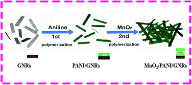
As shown Fig. 1, MnO2/PANI/GNRs composites were fabricated by two-step polymerization. By step-oxidation, there are lots of oxygen-containing groups, such as epoxy, hydroxyl and carboxyl groups in the structure of GNRs.26 These functional groups, acting as anchor sites, enable the aniline units subsequent in situ formation of PANI attaching on the surfaces and edges of GNRs.24 After first step polymerization, since the MnO2 nanorods can be acted as oxidant reactive template for oxidative polymerization of aniline, the aniline monomers absorbed on the surfaces of GNRs can be oxidized to PANI polymer around the surfaces of the MnO2 nanorods, accompanied by the reduction of MnO2 to soluble Mn2+ ions. Therefore, the MnO2/GNRs/PANI ternary composites with MnO2 and GNRs dispersed in the PANI matrix were obtained after second-step polymerization.FT-IR spectra were first used to characterize the formation of MnO2/PANI/GNRs composites. From Fig. 2a, regarding FT-IR spectrum of GNRs, there are characteristic peaks located at 1721, 1238 and 1040 cm−1 which are attributed to the vibration of carbonyl, epoxy and hydroxyl groups, respectively. The peak of 1610 cm−1 is assigned to the stretching vibration of C![[double bond, length as m-dash]](https://www.rsc.org/images/entities/char_e001.gif) C group.24,26 Towards to PANI, the absorption peaks located at 1570 and 1492 cm−1 are ascribed to the C
C group.24,26 Towards to PANI, the absorption peaks located at 1570 and 1492 cm−1 are ascribed to the C![[double bond, length as m-dash]](https://www.rsc.org/images/entities/char_e001.gif) C stretching deformation of the quinoid ring and benzenoid rings in the emeraldine salt. The peaks corresponding to the C–N stretching of secondary aromatic amine and C
C stretching deformation of the quinoid ring and benzenoid rings in the emeraldine salt. The peaks corresponding to the C–N stretching of secondary aromatic amine and C![[double bond, length as m-dash]](https://www.rsc.org/images/entities/char_e001.gif) N stretching appear at 1302 and 1152 cm−1, respectively.33–35 It is worth noting that the FTIR spectra of MnO2/PANI/GNRs almost shows similar peaks as PANI, which indicates the PANI were successfully introduced into the MnO2/PANI/GNRs.
N stretching appear at 1302 and 1152 cm−1, respectively.33–35 It is worth noting that the FTIR spectra of MnO2/PANI/GNRs almost shows similar peaks as PANI, which indicates the PANI were successfully introduced into the MnO2/PANI/GNRs.
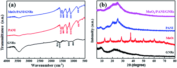 | ||
| Fig. 2 (a) FT-IR spectra of GNRs, PANI and MnO2/PANI/GNR, (b) XRD of GNRs, MnO2, PANI and MnO2/PANI/GNR. | ||
The XRD patterns were also demonstrated the formation of MnO2/PANI/GNRs. For MnO2 nanorods, significant XRD peaks were recorded at 2θ = 12.98°, 18.24°, 25.72°, 28.86°, 37.66°, 41.90°, 49.80°, 56.28°, 60.32°, 65.60° and 69.24°, which could be well-assigned to the (100), (200), (220), (310), (211), (301), (411), (600), (521), (002) and (541) crystal planes of a pure tetragonal the α-MnO2 phase.32,36 For pure polymer of PANI, the diffraction peaks were located at 2θ = 8.62°, 16.34°, 20.41°, 25.32° and 26.92°, illustrating that the in situ polymerized PANI are in highly doped emeraldine salt form.33,34 As for MnO2/PANI/GNRs, a board peak is centered at 2θ = 26.92°, showing similar peaks as PANI except for that the characteristic peaks are becoming obscure, which reveals that the degree of crystallinity of PANI in MnO2/PANI/GNRs become weak owing to the addition of GNRs and MnO2 nanorods. Moreover, no obvious diffraction peaks of GNRs were observed in MnO2/PANI/GNRs indicating that the regular stacks of GNRs are separated by the incorporated MnO2 and PANI, which is beneficial to its final electrochemical property.
Further, SEM and TEM images provided the structure and morphologies of MnO2/PANI/GNRs. As shown in Fig. 3a, there is no tubulous structure and internal and external walls for GNRs, instead, ribbon-like thin graphene layer with crimped edges. From Fig. 3b, the as-prepared MnO2 nanoparticles exhibit rod-like structure. The mean width and length for the MnO2 nanorods are 103.74 nm and 1.95 μm, respectively (Fig. S1 and S2, ESI†). After combination of PANI with two-step polymerization, the GNRs and MnO2 nanorods were filled into the PANI matrix. From Fig. 3c–e, there are distinct MnO2 nanorods embed in PANI. Due to the ultra-thin ribbon-like structure of GNRs, there is almost no GNRs presented in the SEM images of MnO2/PANI/GNRs composites. As pointed in Fig. 3e, there are some curved GNRs inserted into the PANI matrix. As shown in Fig. 3f, the MnO2 nanorods exhibits well crystallized with interplanar distance is 0.49 nm, corresponding to the (200) crystal plane. Brunauer–Emmett–Teller (BET) measurement was also conducted to characterize the structure of MnO2/PANI/GNRs ternary composite. As shown in Fig. S3a (ESI†), the nitrogen adsorption–desorption isotherms of MnO2/GNRs/PANI ternary composite showed a typical type IV with a hysteresis loop at relative pressure (P/P0) of 0.4–1, demonstrating the presence of porous structure of MnO2/GNRs/PANI ternary composite. The Brunauer–Emmett–Teller (BET) specific surface area of the NDPC was estimated as 326.7 m2 g−1. The pore size distribution curve of MnO2/GNRs/PANI ternary composite estimated by Barrett–Joyner–Halenda (BJH), is illustrated in Fig. S3b (ESI†). The MnO2/GNRs/PANI ternary composite is meso-pores with an intensive pore size distribution of ∼4.07 nm. The three-dimensional porous MnO2/GNRs/PANI ternary composite with high specific surface can accommodate the volume change and facilitate penetration of electrolyte and fast diffusion of ions.37–40
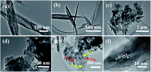 | ||
| Fig. 3 TEM images of (a) GNRs, (b) MnO2 nanorods, (c–e) MnO2/PANI/GNRs composites, (f) HRTEM image of MnO2/PANI/GNRs composites. | ||
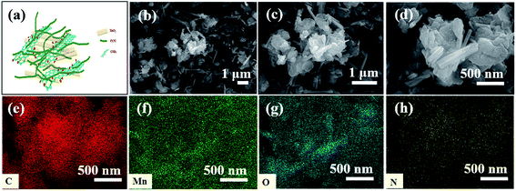
Obviously, as illustrated in Fig. 4a, utilizing the interaction between the GNRs and aniline monomers, the GNRs were first wrapped with PANI polymer chains after first polymerization. Afterward, due to the introduction of MnO2 nanorods, the structures of composites were turned out to be a 3D porous structure with the GNRs interconnected with MnO2, together embedding into PANI matrix, which we can believe this unique structure provides an efficient path for electron and ion transport.35 As observed in Fig. 4b–d, the MnO2/PANI/GNRs show the loose and porous 3D structure with embedding with MnO2 nanorods and GNRs. The elements mapping images in Fig. 4e–h shows the uniform distributions of MnO2 and GNRs in PANI matrix.
To further understanding the composition of MnO2/PANI/GNRs, XPS was carried out and the results are shown in Fig. 5. As for GNRs, the carbon and oxygen signals were observed at 284.6 and 531.9 eV.24 Obviously, after combination, the existences of C, N, O, Mn elements in MnO2/PANI/GNRs can be confirmed from the wide range as shown in Fig. 5b. The XPS spectra of N 1s can be decomposed into three distinct curves, related to 398.6 eV (–N![[double bond, length as m-dash]](https://www.rsc.org/images/entities/char_e001.gif) ), 399.7 eV (–NH–) and 400.1 eV (–N+–). More specifically, the peak located at 400.1 eV is assigned to the quinoid amine and nitrogen cationic radical (–N
), 399.7 eV (–NH–) and 400.1 eV (–N+–). More specifically, the peak located at 400.1 eV is assigned to the quinoid amine and nitrogen cationic radical (–N![[double bond, length as m-dash]](https://www.rsc.org/images/entities/char_e001.gif) ) and the one at 398.6 eV (–N
) and the one at 398.6 eV (–N![[double bond, length as m-dash]](https://www.rsc.org/images/entities/char_e001.gif) ) is due to benzenoid amine.35 The Mn 2p XPS spectrum exhibits two characteristic peaks, Mn 2p3/2 at 643.2 eV and Mn 2p1/2 peak at 654.8 eV, which are attributed to the spin–orbit peaks of α-MnO2. The peak-to-peak separation between Mn 2p1/2 and Mn 2p3/2 level is 11.6 eV, which is approximately the same value as that literature for MnO2,28,32,35 confirming the presence of MnO2 in composites. From the XPS data of MnO2/PANI/GNRs composite, the atomic ratios of C, N, O, Mn elements are 68.86%, 8.31%, 10.51% and 12.32%, respectively.
) is due to benzenoid amine.35 The Mn 2p XPS spectrum exhibits two characteristic peaks, Mn 2p3/2 at 643.2 eV and Mn 2p1/2 peak at 654.8 eV, which are attributed to the spin–orbit peaks of α-MnO2. The peak-to-peak separation between Mn 2p1/2 and Mn 2p3/2 level is 11.6 eV, which is approximately the same value as that literature for MnO2,28,32,35 confirming the presence of MnO2 in composites. From the XPS data of MnO2/PANI/GNRs composite, the atomic ratios of C, N, O, Mn elements are 68.86%, 8.31%, 10.51% and 12.32%, respectively.
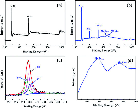 | ||
| Fig. 5 XPS surveys of (a) GNRs and (b) MnO2/PANI/GNRs, high-resolution N 1s (c) and Mn 2p (d) core-level XPS spectra of MnO2/PANI/GNRs. | ||
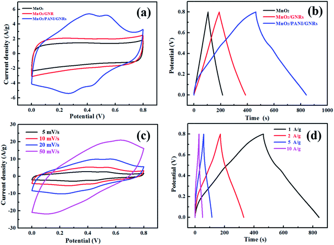
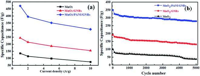
The wrapped PANI with MnO2 and GNRs can not only offer significant capacitance because of it pseudocapacitance character but can also enhance the contact between GNRs and MnO2 nanorods, thus, improving the capacitive performance. For understanding the electrochemical property and qualify the specific capacitance of the MnO2/PANI/GNRs composites, the cyclic voltammograms (CV) measurements of electrode materials for MnO2, MnO2/GNRs and MnO2/PANI/GNRs composites were performed in a 1 M Na2SO4 aqueous solution using a three-electrode system. As shown in Fig. 6a, under the electrochemical window from 0 to 0.8 V with a low scan rate of 5 mV s−1, the MnO2 electrode exhibits rectangular and symmetric CV curves, indicating the ideal pseudocapacitance feature of MnO2. Incorporating with GNR, the increased area of CV curves is probably due to the combined electric double-layer and pseudocapacitive contribution to the total capacitance.25 After introduction of PANI, the CV curve for MnO2/PANI/GNRs ternary composites is different from that of MnO2 and MnO2/GNRs. There are two pairs redox peaks appeared for MnO2/PANI/GNRs. It is attributed to the leucoemeraldine–emeraldine transition and the emeraldine–pernigraniline transition. Consequently, the capacitance of MnO2/PANI/GNRs composites partially comes from faradaic reactions of PANI at the electrode/electrolyte surface, which is different from that of the electric double-layer capacitance of GNRs and pseudocapacitance of MnO2.35,36 Fig. 6c shows the CV curves of MnO2/PANI/GNRs at different scan rates. The current density of the MnO2/PANI/GNRs composites increased with the scan rate and the curve shape is stable. The results demonstrated that the MnO2/PANI/GNRs has good electrochemical stability. Galvanostatic charge/discharge plots (1 A g−1) of MnO2, MnO2/GNRs and MnO2/PANI/GNRs composites were presented in Fig. 6b. During the charging and discharging steps, all the curves exhibit an equilateral triangle shape, indicating high reversibility of the hybrid materials during charge/discharge process. The specific capacitance can be calculated according to Cm = I × Δt/(ΔV × m) from the discharge curves, where Cm is the specific capacitance (F g−1), I is the constant discharge current (A), Δt is the discharge time (s), ΔV is the potential window (V), m is the mass of active material in the working electrode (g).32,35 The gravimetric specific capacitances of MnO2, GNRs/MnO2 and MnO2/PANI/GNRs were 136, 245 and 472 F g−1 at the current density of 1 A g−1, respectively. Obviously, the specific capacitance of MnO2/PANI/GNRs ternary composite is higher than that of MnO2 and GNRs/MnO2, indicating the synergistic effect among GNRs, MnO2 and PANI. From Fig. 6d, the specific capacitance for MnO2/PANI/GNRs ternary composite at 1, 2, 5 and 10 A g−1 were 472, 385, 347 and 306 F g−1. From Table 1, the specific capacitance for MnO2/PANI/GNRs ternary composite was higher than those of other reported previous reported GNR–MnO2 (18%),41 GNR/MnO2,42 PANI–MnO2 nanowires,43 PANI/MnO2,44 and PANI–GNRs-40.45 From Fig. 7a, generally, the specific capacitance decreases with the increase of current density because the diffusion of ions from the electrolyte can gain access to almost all available area of the electrode at low current density, therefore, reaching a higher capacitance. As the current density increases, the capacitance decreases because of the effective interaction between the ion and the electrode is greatly reduced and the deep inside the material does not actually contribute to the capacitance.32 The specific capacitance of MnO2/PANI/GNRs is 472 F g−1 at 1 A g−1 and as high as 306 F g−1 even at 10 A g−1, with a capacitance retention of 65%. While the specific capacitance of MnO2 and MnO2/GNRs reaches 136 F g−1 and 245 F g−1 at a current density of 1 A g−1 and remains at 75 F g−1 and 163 F g−1 at 10 A g−1 with a capacitance retention of 55% and 63%, respectively. The MnO2/PANI/GNRs hybrids not only exhibit high capacitance but also high stable electrochemical performance at high current densities. This may because the special composite structure of MnO2/PANI/GNRs provides numerous porous which can effectively facilitate the ions access to the inside of the composites.14,17,35 On the other hand, the synergist effect between GNRs, MnO2 and PANI significantly reduce the interval conductivity of the composites. As a result, the MnO2/PANI/GNRs composites exhibit high capacity retention at a high current density.
| Materials | C (F g−1) | EI | R | T | Ref |
|---|---|---|---|---|---|
| a El: electrolyte type; R: current density; T: testing method. | |||||
| GNR–MnO2 (18%) | 305 | PAAK/KCl | 0.5 A g−1 | 2-electrode GCD | 41 |
| GNR/MnO2 | 266 | 1 M Na2SO4 | 1 A g−1 | 3-electrode GCD | 42 |
| PANI–MnO2 nanowires | 256 | 1 M KOH | 1 A g−1 | 3-electrode GCD | 43 |
| PANI/MnO2 | 320 | 1 M Na2SO4 | 1 A g−1 | 3-electrode GCD | 44 |
| PANI–GNRs-40 | 340 | 1 M H2SO4 | 0.25 A g−1 | 3-electrode GCD | 45 |
| CGNR/PANI/MnO2 | 496 | 1 M H2SO4 | 1 A g−1 | 3-electrode GCD | 46 |
| MnO2/PANI/GNRs | 472 | 1 M Na2SO4 | 1 A g−1 | 3-electrode GCD | This work |
Due to the synergistic effect of GNRs, MnO2 and PANI, MnO2/PANI/GNRs also exhibits good cyclic electrochemical performance. As shown in Fig. 7b, the galvanostatic charging–discharging cycles for MnO2, MnO2/GNRs and MnO2/PANI/GNRs were carried out at a current density of 10 A g−1 within a voltage range from 0.0 to 0.8 V for 5000 cycles. After 5000 cycles, the MnO2 and MnO2/GNRs-based electrode performed only 35.5% and 68.4% capacitance retention after 1000 cycles. But for MnO2/PANI/GNRs, there is a minor degradation of the specific capacitance with 79.7% of the initial capacitance preserved after 5000 charge–discharge cycles. The improved cycle stability may be deprived from the outstanding stability of the 3D structure constituted by MnO2 nanorods and GNRs, which exhibits excellent mechanical properties. And it effectively prevents the swelling and shrinking of MnO2/PANI/GNRs nanostructure during the long-term cycle test. In addition, the 3D porous structure can greatly reduce the diffusion and migration length of the electrolyte ions during the fast charge/discharge process, and increases the electrochemical utilization of all the active sites.47
To further understand the improvement of electrochemical performance of the MnO2/PANI/GNRs ternary composite electrode, electrochemical impedance spectroscopy (EIS) was carried out within a frequency range from 100 kHz down to 0.01 Hz. The observed semicircle corresponds to a higher-frequency region, whereas the inclined straight line corresponds to the low-frequency. The depression in the semicircle is modeled as the parallel combination of an interfacial charge transfer resistance and double-layer capacitance.48 The inclined straight line at low-frequency represents the ion diffusion and transport due to the pseudocapacitance.49 Fig. 8 represents the Nyquist plots for MnO2, MnO2/GNRs and MnO2/PANI/GNRs electrodes. It is known that the charge transfers resistance (Rct) can be directly measured by the semicircular diameter.11 It can be observed that MnO2/PANI/GNRs exhibits a smaller arc diameter than MnO2 and MnO2/GNRs, indicating that MnO2/PANI/GNRs has low charge transfers resistance with faster ion diffusion rate in Na2SO4 solution. Compared to MnO2/PANI/GNRs, the MnO2/GNRs with a larger arc diameter exhibited slower diffusion rate due to the introduction of GNRs. While the MnO2 presents a larger arc diameter, which might be attributed to the poor conductivity of MnO2. The lowest charge transfer resistance in ternary MnO2/PANI/GNRs implied the excellent rate capability. In addition, in the low frequency region, the slope of the curve shows the Warburg impedance, representing the diffusion and transport of ions in the electrode.47 MnO2/PANI/GNRs shows the most vertical line at lower frequencies, further indicating its high capacitive behavior.
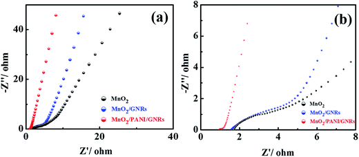 | ||
| Fig. 8 (a) Nyquist plots of MnO2, MnO2/GNRs and MnO2/PANI/GNRs ternary composites and (b) partial enlarged Nyquist plots of MnO2, MnO2/GNRs and MnO2/PANI/GNRs. | ||
4. Conclusion
In summary, unique MnO2/PANI/GNRs composite have been successfully synthesized via a two-step in situ process. The as-prepared composites electrode exhibits an excellent specific capacitance of 472 F g−1 at the current density of 1 A g−1 in 1 M Na2SO4 aqueous solution. In addition, the MnO2/PANI/GNRs show high electrochemical stability in cycling stability with 79.7% capacitance retention after 5000 cycles. Such intriguing electrochemical performance was because of the unique 3D porous structure constituted by MnO2 and GNRs, leading to an excellent rate performance and cycling stability. On the other hand, the synergistic effects of GNRs, PANI and MnO2 have overcome the disadvantages of each component to some extent, therefore, resulting in a robust capacitive performance. The facile and effective synthetic strategy, we believe, can not only be employed for the fabrication of robust high-performance energy storage material containing carbon materials, metal oxide and conducting polymers, but also can be extended to other material preparation for the development of advanced electrode materials, which may pave an avenue for the practical applications of supercapacitors.Acknowledgements
This research was supported by leading talent program of Shanghai, Sailing program of Shanghai Science and Technology Commission (15YF1404700), Startup Fund for New Talent, Shanghai University of Electric Power (K-2014-046), National Nature Science Foundation of China (No. 21604051) and Science and Technology Commission of Shanghai Municipality (No. 14JC1402500). The study was also sponsored by “Chenguang Program” supported by Shanghai Education Development Foundation and Shanghai Municipal Education Commission (14CG54). Additionally, the authors are greatly indebted to the financial supports from the Projects of Science and Technology Department of Guizhou Province (No. [2016]7079), the Projects of Education Department of Guizhou Province ([2016]162). Finally, we thank the International Joint Laboratory on Resource Chemistry (IJLRC).References
- G. Wang, L. Zhang and J. Zhang, Chem. Soc. Rev., 2012, 41, 797–828 RSC.
- M. Salanne, B. Rotenberg, K. Naoi, K. Kaneko, P. L. Taberna, C. P. Grey, B. Dunn and P. Simon, Nat. Energy, 2016, 1, 16070 CrossRef CAS.
- W. Chen, R. B. Rakhi, L. Hu, X. Xie, Y. Cui and H. N. Alshareef, Nano Lett., 2011, 11, 5165–5172 CrossRef CAS PubMed.
- P. Simon and Y. Gogotsi, Nat. Mater., 2008, 7, 845–854 CrossRef CAS PubMed.
- B. Fang, A. Bonakdarpour, M.-S. Kim, J. H. Kim, D. P. Wilkinson and J.-S. Yu, Microporous Mesoporous Mater., 2013, 182, 1–7 CrossRef CAS.
- B. Fang, J. H. Kim, M.-S. Kim, A. Bonakdarpour, A. Lam, D. P. Wilkinson and J.-S. Yu, J. Mater. Chem., 2012, 22, 19031–19038 RSC.
- B. Fang and L. Binder, J. Power Sources, 2006, 163, 616–622 CrossRef CAS.
- H. Ji, X. Zhao, Z. Qiao, J. Jung, Y. Zhu, Y. Lu, L. L. Zhang, A. H. MacDonald and R. S. Ruoff, Nat. Commun., 2014, 5, 3317 Search PubMed.
- F. Bonaccorso, L. Colombo, G. Yu, M. Stoller, V. Tozzini, A. C. Ferrari, R. S. Ruoff and V. Pellegrini, Science, 2015, 347, 1246501 CrossRef PubMed.
- L. Q. Mai, A. Minhas-Khan, X. Tian, K. M. Hercule, Y. L. Zhao, X. Lin and X. Xu, Nat. Commun., 2013, 4, 2923 Search PubMed.
- Y. Liu, D. Yan, R. Zhuo, S. Li, Z. Wu, J. Wang, P. Ren, P. Yan and Z. Geng, J. Power Sources, 2013, 242, 78–85 CrossRef CAS.
- B. Brown, I. A. Cordova, C. B. Parker, B. R. Stoner and J. T. Glass, Chem. Mater., 2015, 27, 2430–2438 CrossRef CAS.
- C. Yuan, H. B. Wu, Y. Xie and X. W. Lou, Angew. Chem., 2014, 53, 1488–1504 CrossRef CAS PubMed.
- C. Pan, H. Gu and L. Dong, J. Power Sources, 2016, 303, 175–181 CrossRef CAS.
- D. Wang, Y. Xiao, X. Luo, Z. Wu, Y.-J. Wang and B. Fang, ACS Sustainable Chem. Eng., 2017, 5, 2509–2515 CrossRef CAS.
- M. Kim, C. Lee and J. Jang, Adv. Funct. Mater., 2014, 24, 2489–2499 CrossRef CAS.
- H. Cao, X. Zhou, Y. Zhang, L. Chen and Z. Liu, J. Power Sources, 2013, 243, 715–720 CrossRef CAS.
- N. Ashok Kumar and J. B. Baek, Chem. Commun., 2014, 50, 6298–6308 RSC.
- M. N. Hyder, R. Kavian, Z. Sultana, K. Saetia, P.-Y. Chen, S. W. Lee, Y. Shao-Horn and P. T. Hammond, Chem. Mater., 2014, 26, 5310–5318 CrossRef CAS.
- L. Wang, X. Lu, S. Lei and Y. Song, J. Mater. Chem. A, 2014, 2, 4491–4509 CAS.
- Y. Huang, J. Liang and Y. Chen, Small, 2012, 8, 1805–1834 CrossRef CAS PubMed.
- D. V. Kosynkin, A. L. Higginbotham, A. Sinitskii, J. R. Lomeda, A. Dimiev, B. K. Price and J. M. Tour, Nature, 2009, 458, 872–876 CrossRef CAS PubMed.
- L. Jiao, L. Zhang, X. Wang, G. Diankov and H. Dai, Nature, 2009, 458, 877–880 CrossRef CAS PubMed.
- D. K. James and J. M. Tour, Macromol. Chem. Phys., 2012, 213, 1033–1050 CrossRef CAS.
- L. Li, A. R. Raji, H. Fei, Y. Yang, E. L. Samuel and J. M. Tour, ACS Appl. Mater. Interfaces, 2013, 5, 6622–6627 CAS.
- F.-H. Hsu and T.-M. Wu, Synth. Met., 2014, 198, 188–195 CrossRef CAS.
- V. Sahu, S. Shekhar, R. K. Sharma and G. Singh, ACS Appl. Mater. Interfaces, 2015, 7, 3110–3116 CAS.
- L. Li, A. R. Raji and J. M. Tour, Adv. Mater., 2013, 25, 6298–6302 CrossRef CAS PubMed.
- Q. Li, J. Liu, J. Zou, A. Chunder, Y. Chen and L. Zhai, J. Power Sources, 2011, 196, 565–572 CrossRef CAS.
- G. Wang, Q. Tang, H. Bao, X. Li and G. Wang, J. Power Sources, 2013, 241, 231–238 CrossRef CAS.
- P. Xiong, C. Hu, Y. Fan, W. Zhang, J. Zhu and X. Wang, J. Power Sources, 2014, 266, 384–392 CrossRef CAS.
- K. Dai, L. Lu, C. Liang, J. Dai, Q. Liu, Y. Zhang, G. Zhu and Z. Liu, Electrochim. Acta, 2014, 116, 111–117 CrossRef CAS.
- M. Kim, C. Lee, Y. D. Seo, S. Cho, J. Kim, G. Lee, Y. K. Kim and J. Jang, Chem. Mater., 2015, 27, 6238–6248 CrossRef CAS.
- Q. Hao, X. Xia, W. Lei, W. Wang and J. Qiu, Carbon, 2015, 81, 552–563 CrossRef CAS.
- G. Han, Y. Liu, L. Zhang, E. Kan, S. Zhang, J. Tang and W. Tang, Sci. Rep., 2014, 4, 4824 CrossRef PubMed.
- H.-M. Lee, G. H. Jeong, D. W. Kang, S.-W. Kim and C.-K. Kim, J. Power Sources, 2015, 281, 44–48 CrossRef CAS.
- B. Fang, Y. Xing, A. Bonakdarpour, S. Zhang and D. P. Wilkinson, ACS Sustainable Chem. Eng., 2015, 3, 2381–2388 CrossRef CAS.
- B. Fang, A. Bonakdarpour, K. Reilly, Y. Xing, F. Taghipour and D. P. Wilkinson, ACS Appl. Mater. Interfaces, 2014, 6, 15488–15498 CAS.
- B. Fang, J. H. Kim, M.-S. Kim and J.-S. Yu, Acc. Chem. Res., 2013, 46, 1397–1406 CrossRef CAS PubMed.
- H. Xia, Y. Wang, J. Lin and L. Lu, Nanoscale Res. Lett., 2012, 7, 33 CrossRef PubMed.
- M. Liu, W. W. Tjiu, J. Pan, C. Zhang, W. Gao and T. Liu, Nanoscale, 2014, 6, 4233–4242 RSC.
- M.-S. Wu and Y.-H. Fu, Carbon, 2013, 60, 236–245 CrossRef CAS.
- L. Chen, Z. Song, G. Liu, J. Qiu, C. Yu, J. Qin, L. Ma, F. Tian and W. Liu, J. Phys. Chem. Solids, 2013, 74, 360–365 CrossRef CAS.
- M. Liu, Y.-E. Miao, C. Zhang, W. W. Tjiu, Z. Yang, H. Peng and T. Liu, Nanoscale, 2013, 5, 7312–7320 RSC.
- L. Li, A.-R. O. Raji, H. Fei, Y. Yang, E. L. G. Samuel and J. M. Tour, ACS Appl. Mater. Interfaces, 2013, 5, 6622–6627 CAS.
- Z. Yin, H. Zhou, C. Fu, N. Zhang, D. Liu and Y. Kuang, RSC Adv., 2016, 6, 41142–41150 RSC.
- X. Sun, M. Gan, L. Ma, H. Wang, T. Zhou, S. Wang, W. Dai and H. Wang, Electrochim. Acta, 2015, 180, 977–982 CrossRef CAS.
- Y. Liu, Y. Ma, S. Guang, F. Ke and H. Xu, Carbon, 2015, 83, 79–89 CrossRef CAS.
- H. Li, Y. He, V. Pavlinek, Q. Cheng, P. Saha and C. Li, J. Mater. Chem. A, 2015, 3, 17165–17171 CAS.
Footnote |
| † Electronic supplementary information (ESI) available. See DOI: 10.1039/c7ra05443b |
| This journal is © The Royal Society of Chemistry 2017 |

