A general strategy to simulate osmotic energy conversion in multi-pore nanofluidic systems†
Feilong
Xiao‡
a,
Danyan
Ji‡
b,
Hao
Li
a,
Jialiang
Tang
a,
Yaping
Feng
b,
Liping
Ding
c,
Liuxuan
Cao
*a,
Ning
Li
a,
Lei
Jiang
 b and
Wei
Guo
 *b
*b
aCollege of Energy, Xiamen University, Xiamen, Fujian 361005, P. R. China. E-mail: caoliuxuan@xmu.edu.cn
bCAS Key Laboratory of Bio-inspired Materials and Interfacial Science, Technical Institute of Physics and Chemistry, Chinese Academy of Sciences, Beijing 100190, P. R. China. E-mail: wguo@iccas.ac.cn
cCenter for Physiochemical Analysis and Measurement, Institute of Chemistry, Chinese Academy of Sciences, Beijing 100190, P. R. China
First published on 19th February 2018
Abstract
As a type of clean energy resource, salinity gradient power between seawater and river water is important to satisfy the ever-growing energy demand on earth. In the recent years, the use of reverse electrodialysis in biomimetic nanofluidic systems has become a promising way for large-scale and high-efficiency harvesting of the salinity gradient power and surpasses the conventional polymeric ion-exchange membrane-based process. With regard to practical applications, significant efforts have been made towards the design and fabrication of high-performance and economically viable materials and devices. However, while extrapolating from single nanopores to multi-pore membrane materials, the commonly used linear amplification method causes severe deviation from the actual experimental value obtained on nanoporous membranes, particularly at a high pore density. An appropriate simulation method is therefore highly demanded and a great challenge. Herein, we present a general strategy for multi-pore nanofluidic systems by taking the influence of neighbouring nanopores into consideration. We have found that the fourth nearest-neighbor approximation is sufficiently precise for simulation in nanoporous systems. The simulation data are in good agreement with the experimental results. The simulation method provides insights for understanding the pore–pore interaction in porous nanofluidic systems and for the design of high-performance devices.
Introduction
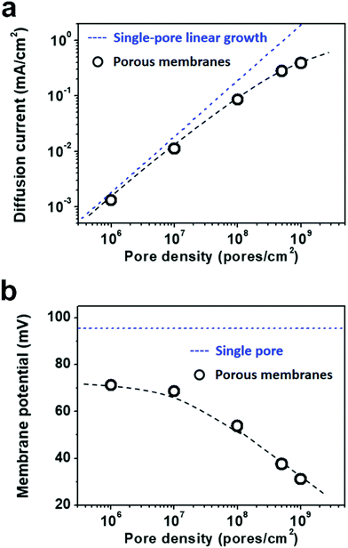
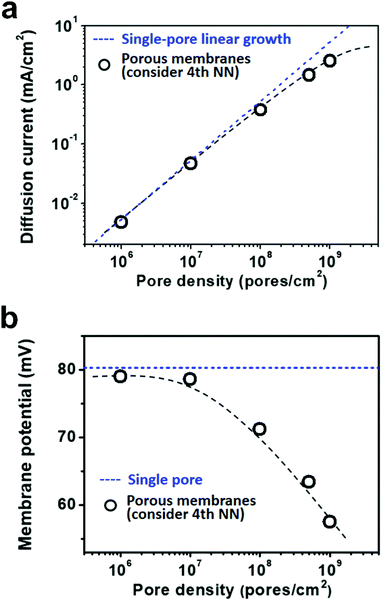
Due to the global energy shortage and the environmental problems caused by the burning of fossil fuels, development of a clean energy technology is crucial for the sustainable development of human civilization.1–4 Salinity gradient power between seawater and river water, a type of clean energy resource, is a potential candidate of energy source to satisfy the ever-growing energy demand on earth.5 Inspired by the biological ion channels on cell membranes, biomimetic nanofluidic systems in solid-state materials are used for osmotic energy conversion as effectively as the electrogenic cells.6–8 In 2010, we have demonstrated the proof-of-concept nanofluidic reverse electrodialysis system (NREDS) that converts salinity gradient energy into electric power with track-etched single nanopores in polymer membranes.9 We achieved a maximum power output of 26 pW from single-pore devices. It is also the first time that the energy conversion mechanism in artificial nanofluidic systems is connected with the ultra-strong bioelectrogenetic capability found in electric eels.10 Besides polymeric membranes,11,12 the NREDS has been widely realized in silicon-based materials,13,14 alumina membranes,15 and monolayer or restacked 2D materials.16–20 Recently, Gao et al. reported a mesoporous carbon-capped alumina membrane, termed ionic diode membrane, showing superior performance in harvesting the salinity gradient power.21 The output power density approaches 3.46 W m−2, which outperforms that of the commercial ion-exchange membranes.With regard to practical applications, significant efforts have been made towards extrapolating single-pore nanofluidic devices to multi-pore membrane materials.22 In literature, a linear amplification method is widely used to estimate the performance of multi-pore membrane materials based on the experimental measurements on single-pore devices.23,24 This assumption may cause severe deviation from the actual value obtained on nanoporous membranes, particularly at a high pore density. For example, we have experimentally observed that once the pore density in the polymer membrane increases to above 1 × 10⁸ pores per cm2, both the diffusion current and the membrane potential obviously deviate from the trend of single-pore linear growth or the value measured on a single-pore device (Fig. 1a and b). At a high pore density, the pore–pore interaction becomes non-negligible.25 Thus, the single-pore-based linear approximation may eventually lead to severe overestimation in the overall performance.
From the theoretical aspects, the continuum model based on the coupled Poisson and Nernst–Planck (PNP) equations has been widely proven to be the most effective and convenient method to investigate the ion-transport phenomena through ion-selective nanopores.26–30 However, these existing PNP models deal with single nanopores. An appropriate simulation method for the multi-pore nanofluidic systems becomes highly demanded and challenging.
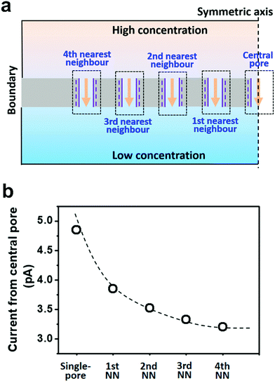
Herein, we presented a general strategy to simulate the osmotic energy conversion in multi-pore nanofluidic systems. Besides the investigated nanopore (the central pore, Fig. 2a), we considered diffusive ion transport through its n-th nearest neighbouring nanopores. The calculated region therefore includes 2n + 1 parallel nanopores (Fig. 2a). In this way, the influence of the adjacent nanopores can be involved in the model as environmental conditions for the central pore. We have found that the fourth nearest-neighbor approximation is sufficiently precise to meet the experimental results. The simulation method provides an insight for understanding the performance degradation due to pore–pore interactions and guidance for the design of high-performance nanofluidic energy devices.
Experimental
Nanopore fabrication
Polyethylene terephthalate (PET, Hostaphan RN12 Hoechst, 12 μm-thick) films were irradiated with swift heavy ions (Au) of 11.4 MeV per nucleon at the linear accelerator UNILAC (GSI, Darmstadt, Germany). The irradiated PET films were treated with UV light (λ = 365 nm, 4 mW cm−2) for 1 hour per face. Then, the PET films were chemically etched with a sodium hydroxide solution (2 M) at 50 °C on both sides. The size of the nanopores is controlled by the etching time.31 After etching, the PET films were first immersed in a hydrochloric acid solution (0.1 M) for ten minutes to neutralize the residual alkaline solution, and then, they were thoroughly washed with pure water. The geometry of the resulting nanopores was determined by conducting scanning electron microscopy (SEM) on the surface and cross section of the membrane (Fig. S1, ESI†). The mean diameter of the cylindrical nanopores used in this study was about 22 nm.Electrical measurement
A piece of single-pore or porous PET film was sandwiched between two solution reservoirs.32–34 The pore density varied from 1 × 10⁶ to 1 × 10⁹ pores per cm2. A fixed concentration difference of 100|1 mM KCl solution was applied across the membrane. Current recordings were carried out using a Keithley 6487 picoammeter/voltage source through Ag/AgCl electrodes (Fig. S2, ESI†). The potential difference at the electrode/electrolyte interface was calibrated with a saturated calomel reference electrode.11 The diffusion current and membrane potential were then determined by the intercepts on the current and voltage axes, respectively.Numerical simulation methods
The salinity-gradient-driven ion-transport through the multi-pore nanofluidic systems was investigated by numerical simulation based on the Poisson and Nernst–Planck (PNP) equations.35 The finite element method was employed to solve the coupled partial differential equations with proper boundary conditions.36 The computational domain was discretized into non-uniform triangular elements. The maximum element size of the boundary mesh was set as 1 × 10⁻¹⁰ m. The diffusion current was calculated by integrating the current density over the cross-section of the nanopores.In the model, the size of the reservoirs is set as a0 = 5 μm and b = 2 μm. 2a1 is the distance between the axes of adjacent pores, corresponding to the pore density in a 2D planar model (Fig. 3a). By changing the value of a1, the pore density can be adjusted from 1 × 10⁶ to 1 × 10⁹ pores per cm2 (Table S1, ESI†). The pore length (L), the pore diameter (D), and the surface charge density (σ) were set to 1 μm, 10 nm, and −0.06 C m−2, respectively. The concentration difference across the model nanopore was set as 100|1 mM. Details of the numerical simulation method are presented in ESI† and references therein.
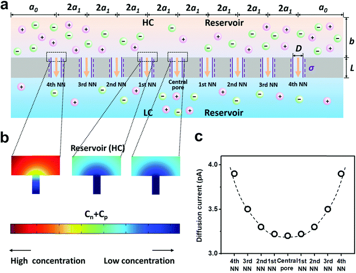 | ||
| Fig. 3 Diffusive ion transport under the 4th nearest-neighbor approximation. (a) Schematic of the model (ESI†). (b) The local ion concentration at the high-concentration end of the central, the first nearest neighboring, and the fourth nearest neighboring nanopores. (c) Diffusion current through individual nanopores was calculated separately. The applied concentration difference was 100|1 mM. a0 = 5 μm, b = 2 μm, and a1 = 300 nm, corresponding to the numeric pore density of 3 × 10⁸ pores per cm2. The pore length (L) was 1 μm. The pore diameter (D) was 10 nm, and the surface charge density (σ) was −0.06 C m−2. | ||
Results and discussion
To take the pore–pore interactions into consideration, in addition to the investigated nanopore (the central pore, Fig. 2a), we also calculated the diffusive ion-transport through its adjacent nanopores, termed the nth nearest-neighbor approximation. In a 2-D planar model (with mirror symmetry), high-(100 mM) and low-concentration (1 mM) electrolyte solutions were placed at the two ends of the cylindrical nanopore array. The calculated region included 2n + 1 parallel nanopores. The inter-pore distance was set as 600 nm. However, the final diffusion current and membrane potential were extracted from the central pore. In this way, the influence of the surrounding nanopores was involved in the model as environmental conditions for the central pore.As shown in Fig. 2b, if the calculated region contains only one pore (the single-pore condition), the resulting diffusion current approaches 4.9 pA. With an increase in the number of considered nearest neighbors, the diffusion current gradually drops down to 3.2 pA and eventually reaches a plateau when the 4th nearest-neighbor approximation is considered (totally nine nanopores have been considered in the model). The decrement in the diffusion current through the central pore results from degradation in the effective concentration difference when the neighboring nanopores are taken into consideration (Fig. S3, ESI†). To balance the computation scale of high-order approximation, we proposed that the 4th nearest-neighbor approximation was sufficiently precise to reach convergent results in multi-pore nanofluidic systems.
Furthermore, we separately calculated the ion concentration distribution and the resulting diffusive ionic current through the nine nanopores under the 4th nearest-neighbor approximation (Fig. 3a). At the high-concentration (HC) end, the ion concentration distribution near the central pore orifice is very similar to that of its first nearest neighboring (1st NN) pores, but it is in sharp contrast to that of the fourth nearest neighboring (4th NN) pores near the boundary (Fig. 3b). This trend can also be observed in the diffusion current from individual nanopores (Fig. 3c). The inner pores, which are far away from the boundary, are less influenced by the boundary conditions, but are more sensitive to the presence of neighbouring nanopores. However, the pores close to the reservoir boundary are more affected by the boundary conditions. In porous materials, the number of inner pores (proportional to the membrane area) is far more than that of the boundary pores (proportional to the lateral size). Therefore, the influence of the neighboring pores becomes important in the simulation. In addition, the pore–pore interactions induce more severe ion concentration polarization (ICP) at the inner pores (Fig. S4, ESI†),37,38 leading to the degradation of the effective concentration difference and eventually resulting in a lower diffusion current.
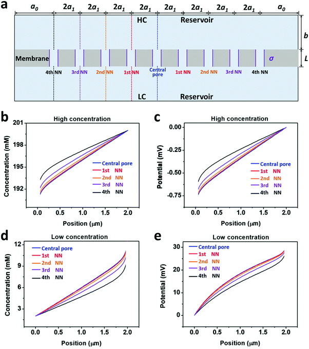
From the governing equations (ESI†), the ion transport behavior through the nanopores is co-determined by the local ion concentration (c) and the local electric potential (Φ). Under the 4th nearest-neighbor approximation, we compared the local ion concentration and electric field distribution near the two ends of the central pore and its neighboring nanopores (Fig. 4a). At both the high- and low-concentration ends, the ion concentration and electric potential distribution near the central pore and its first nearest-neighbor (1st NN) pores are almost identical (Fig. 4b–d). However, their divergences become remarkable when the pore is located closer to the boundary such as the cases of the third and fourth nearest-neighbor pores (3rd NN and 4th NN). These evidences verify that higher orders of nearest-neighbor approximation would not further improve the accuracy of the simulation result. In this regard, we think that the 4th nearest-neighbor approximation is therefore sufficient to obtain convergent results.
Finally, we used the 4th nearest-neighbor approximation to simulate the osmotic energy conversion with high-density nanoporous membranes. The pore density is controlled by adjusting the inter-pore distance in a 2D configuration (ESI†). The pore density varies from 1 × 10⁶ to 1 × 10⁹ pores per cm2, corresponding to the experimental parameters. The relationship between the pore density and the inter-pore distance is listed in Table S1 (ESI†). The length and diameter of the individual model nanopore were 1 μm and 10 nm, respectively. The surface charge density was fixed to −0.06 C m−2, which was consistent with the value used in literature.39
As shown in Fig. 5a, the diffusion current density grows non-linearly with pore density, particularly at a high pore density. In the low pore density region (<107 pores per cm2), the increment of diffusion current generally obeys the predicted trend of single-pore linear growth. However, when the pore density further increases to above 1 × 10⁷ pores per cm2, the inter-pore distance shortens down to less than 3000 nm. There is no sufficient room outside the nanopores for ion migration from the bulk to the near-pore region. Thus, the pore–pore interactions become important in this crowded region, and the diffusion current density begins to deviate from the linear growth. This trend is generally consistent with the experimental data shown in Fig. 1a.
 | ||
| Fig. 5 Simulation results of diffusion current (a) and membrane potential (b) with respect to the pore density under the fourth nearest-neighbor approximation. (a) In the low pore density (<107 pores per cm2) range, the diffusion current density generally obeys the single-pore linear growth. But remarkable divergence emerges in the high pore density range. (b) Taking the influence of adjacent pores into consideration once, the degradation in membrane potential can also be found in the high pore density (>107 pores per cm2) range. These simulation results coincide with the experimental data shown in Fig. 1. | ||
Similarly, by considering the influence of adjacent nanopores, the membrane potential in porous model systems also falls down with the increasing pore density (Fig. 5b). This trend is in accordance with the experimental results shown in Fig. 1b. Considering the symmetry of multiple parallel cylindrical nanopores, we used a 2D planar model in the simulation, not the 2D model with axial symmetry.11 Therefore, the simulation results might be somewhat lower than the experimental value. The ICP effect in nanopores can also be influenced by the pore size, surface charge distribution, pore length etc. However, in the present study, we focused mainly on the pore-density dependence. This modelling strategy qualitatively simulates performance degradation when the nanopores become over-crowded in the membrane. Thus, it can be further used to study ion transport in multi-pore nanofluidic systems.
Conclusions
In conclusion, we have experimentally found that with the increasing pore density, the commonly used single-pore-based linear amplification method leads to severe overestimation in the overall performance in the osmotic energy conversion. To faithfully reflect this degradation in the simulation process, we proposed a general strategy to take the influence of adjacent nanopores into consideration by involving the diffusive ion transport through the nearest neighbouring nanopores in our model. We have found that the fourth nearest-neighbor approximation is sufficient to obtain convergent results while balancing the computational scale. The simulation results agree well with the experimental data. The linear amplification may have its meaning when the numeric pore density is lower than 107 pores per cm2. Otherwise, it would cause severe overestimation in the overall performance. This method can be further employed to understand the fundamental ion-transport properties in porous membranes and provide insights for the design and optimization of the device.Conflicts of interest
There are no conflicts of interest to declare.Acknowledgements
This work was financially supported by the National Natural Science Foundation of China (11405143, 21522108, 11335003) and the Fundamental Research Funds for the Central Universities of China, Grant No. 20720170050.Notes and references
- S. Pacala and R. Socolow, Science, 2004, 305, 968 CrossRef CAS PubMed.
- D. Lindley, Nature, 2009, 458, 138 CrossRef CAS PubMed.
- L. Xia, L. Yu, D. Hu and G. Z. Chen, Mater. Chem. Front., 2017, 1, 584 RSC.
- K. Liu, H. Zhong, F. Meng, X. Zhang, J. Yan and Q. Jiang, Mater. Chem. Front., 2017, 1, 2155 RSC.
- B. E. Logan and M. Elimelech, Nature, 2012, 488, 313 CrossRef CAS PubMed.
- W. Guo, Y. Tian and L. Jiang, Acc. Chem. Res., 2013, 46, 2834 CrossRef CAS PubMed.
- W. Guo and L. Jiang, Sci. China Mater., 2014, 57, 2 CrossRef.
- Y. Feng, W. Zhu, W. Guo and L. Jiang, Adv. Mater., 2017, 29, 1702773 CrossRef PubMed.
- W. Guo, L. Cao, J. Xia, F. Q. Nie, W. Ma, J. Xue, Y. Song, D. Zhu, Y. Wang and L. Jiang, Adv. Funct. Mater., 2010, 20, 1339 CrossRef CAS.
- J. Xu and D. A. Lavan, Nat. Nanotechnol., 2008, 3, 666 CrossRef CAS PubMed.
- L. Cao, W. Guo, W. Ma, L. Wang, F. Xia, S. Wang, Y. Wang, L. Jiang and D. Zhu, Energy Environ. Sci., 2011, 4, 2259 CAS.
- K. Kwon, S. J. Lee, L. Li, C. Han and D. Kim, Int. J. Energy Res., 2014, 38, 530 CrossRef CAS.
- D. K. Kim, C. Duan, Y. F. Chen and A. Majumdar, Microfluid. Nanofluid., 2010, 9, 1215 CrossRef CAS.
- L. Sang, H. Kim and D. K. Kim, Energies, 2016, 9, 49 CrossRef.
- J. Kim, S. J. Kim and D. K. Kim, Energy, 2013, 51, 413 CrossRef CAS.
- R. C. Rollings, A. T. Kuan and J. A. Golovchenko, Nat. Commun., 2016, 7, 11408 CrossRef CAS PubMed.
- J. Feng, M. Graf, K. Liu, D. Ovchinnikov, D. Dumcenco, M. Heiranian, V. Nandigana, N. R. Aluru, A. Kis and A. Radenovic, Nature, 2016, 536, 197 CrossRef CAS PubMed.
- L. Wang, Y. Feng, Y. Zhou, M. Jia, G. Wang, W. Guo and L. Jiang, Chem. Sci., 2017, 8, 4381 RSC.
- H. Cheng, Y. Zhou, Y. Feng, W. Geng, Q. Liu, W. Guo and L. Jiang, Adv. Mater., 2017, 29, 1700177 CrossRef PubMed.
- J. Gao, W. Guo, H. Geng, X. Hou, Z. Shuai and L. Jiang, Nano Res., 2012, 5, 99 CrossRef CAS.
- J. Gao, W. Guo, D. Feng, H. Wang, D. Zhao and L. Jiang, J. Am. Chem. Soc., 2014, 136, 12265 CrossRef CAS PubMed.
- A. Siria, M.-L. Bocquet and L. Bocquet, Nat. Rev. Chem., 2017, 1, 0091 CrossRef.
- A. Siria, P. Poncharal, A.-L. Biance, R. Fulcrand, X. Blase, S. T. Purcell and L. Bocquet, Nature, 2013, 494, 455 CrossRef CAS PubMed.
- J. D. Feng, M. Graf, K. Liu, D. Ovchinnikov, D. Dumcenco, M. Heiranian, V. Nandigana, N. R. Aluru, A. Kis and A. Radenovic, Nature, 2016, 536, 197 CrossRef CAS PubMed.
- A. Gadaleta, C. Sempere, S. Gravelle, A. Siria, R. Fulcrand, C. Ybert and L. Bocquet, Phys. Fluids, 2014, 26, 012005 CrossRef.
- J. Cervera, B. Schiedt and P. Ramírez, Europhys. Lett., 2005, 71, 35 CrossRef CAS.
- I. D. Kosińska, I. Goychuk, M. Kostur, G. Schmid and P. Hänggi, Phys. Rev. E: Stat., Nonlinear, Soft Matter Phys., 2008, 77, 031131 CrossRef PubMed.
- H. I. Jeong, H. J. Kim and D. K. Kim, Energy, 2014, 68, 229 CrossRef.
- Z. P. Zeng, Y. Ai and S. Z. Qian, Phys. Chem. Chem. Phys., 2014, 16, 2465 RSC.
- L. X. Cao, F. L. Xiao, Y. P. Feng, W. W. Zhu, W. X. Geng, J. L. Yang, X. P. Zhang, N. Li, W. Guo and L. Jiang, Adv. Funct. Mater., 2017, 27, 1604302 CrossRef.
- W. Guo, J. Xue, L. Wang and Y. Wang, Nucl. Instrum. Methods Phys. Res., Sect. B, 2008, 266, 3095 CrossRef CAS.
- W. Guo, H. W. Xia, L. X. Cao, F. Xia, S. T. Wang, G. Z. Zhang, Y. L. Song, Y. G. Wang, L. Jiang and D. B. Zhu, Adv. Funct. Mater., 2010, 20, 3561 CrossRef CAS.
- W. Guo, F. Hong, N. N. Liu, J. Y. Huang, B. Y. Wang, R. X. Duan, X. D. Lou and F. Xia, Adv. Mater., 2015, 27, 2090 CrossRef CAS PubMed.
- Y. Jiang, Y. Feng, J. Su, J. Nie, L. Cao, L. Mao, L. Jiang and W. Guo, J. Am. Chem. Soc., 2017, 139, 18739 CrossRef CAS PubMed.
- L. Cao, W. Guo, Y. Wang and L. Jiang, Langmuir, 2012, 28, 2194 CrossRef CAS PubMed.
- H. C. Yeh, C. C. Chang and R. J. Yang, RSC Adv., 2013, 4, 2705 RSC.
- S. J. Kim, Y.-C. Wang, J. H. Lee, H. Jang and J. Han, Phys. Rev. Lett., 2007, 99, 044501 CrossRef PubMed.
- J. Gao, A. R. Koltonow, K. Raidongia, B. Beckerman, N. Boon, E. Luijten, M. Olvera de la Cruz and J. Huang, Mater. Chem. Front., 2018 10.1039/c7qm00620a.
- J. Cervera, A. Alcaraz, B. Schiedt, R. Neumann and P. Ramírez, J. Phys. Chem. C, 2007, 111, 12265 CAS.
Footnotes |
| † Electronic supplementary information (ESI) available. See DOI: 10.1039/c8qm00031j |
| ‡ These authors contribute equally. |
| This journal is © the Partner Organisations 2018 |

