High-efficiency ultrapure green organic light-emitting diodes†
Hirohiko
Fukagawa
 *a,
Taku
Oono
a,
Yukiko
Iwasaki
a,
Takuji
Hatakeyama
 b and
Takahisa
Shimizu
 a
a
aNHK Science & Technology Research Laboratories, Tokyo, 1578510, Japan. E-mail: fukagawa.h-fe@nhk.or.jp
bDepartment of Chemistry, School of Science and Technology, Kwansei Gakuin University, Hyogo, 6691337, Japan
First published on 29th January 2018
Abstract
To expand the color reproduction area of displays as stipulated in the Recommendation ITU-R BT.2020 for ultrahigh-definition displays, quantum dot- and perovskite-based LEDs have been intensively examined. However, it is difficult to satisfy the BT.2020 standard using quantum dot-LEDs, and the efficiency and operational stability of perovskite-based LEDs are insufficient. Herein, we report the first-ever organic LED that can emit ultrapure green light with high efficiency. The key to success is the combined use of a platinum-based pure green emitter and a boron-based host material. The optimized bottom-emitting OLED exhibited the maximum current efficiency of 84 cd A−1 with CIE x–y coordinates of (0.27, 0.67). Furthermore, the CIE x–y coordinates reached (0.18, 0.74) with the use of a top-emitting structure comprising a microcavity structure and an organic capping layer. The optimized top-emitting OLED exhibited a high current efficiency of 98 cd A−1 and CIE color coordinates of (0.18, 0.74) with a small angular color shift of Δxy = 0.03 at viewing angles of 0° to 60°. The newly developed ultrapure green OLED enabled the coverage of 91% of the BT.2020 standard in the CIE 1931 color gamut.
Introduction
In recent years, several researchers have attempted to expand the color reproduction area of displays in accordance with the Recommendation ITU-R BT.2020 (Rec. 2020) for ultrahigh-definition displays.1 In the color gamut of BT.2020, almost all colors in nature can be reproduced.2 However, the BT.2020 standard requires monochromatic RGB primaries with an extremely narrow bandwidth, which particularly poses a significant challenge for green emitters. That is because ultrapure green emission requires a strictly defined peak emission wavelength and narrower spectrum of half width as compared to the other colors.3 In recent years, quantum dot (QD) and perovskite materials have been thought to be promising candidates for LEDs, which achieve a wide color gamut for the BT.2020 standard. Significant improvement in the performance of QD-LEDs, the first study of which was reported in 1995, has been noted.4,5 Recent QD-LEDs reportedly cover 90% of the BT.2020 color space using cadmium-based QDs. In addition, perovskite-LEDs exhibit a sharp emission spectrum.6,7 However, QD and perovskite LEDs exhibit challenges that need to be resolved. For QD-LEDs, it is difficult to demonstrate the ultrapure green emission due to the relatively large emission bandwidth, with a full width at half maximum (FWHM) of about 30 nm.3,6 On the other hand, the efficiency and operational stability of LEDs using perovskites are still low though the feasibility of the ultrapure green emission has been demonstrated.6In contrast to perovskite- and QD-LEDs, organic OLEDs (OLEDs) have been intensively examined as a next-generation display/lighting technology for ∼30 years. Although OLEDs can achieve high efficiency and high operational stability, emission with high color purity has been difficult for OLEDs because of the broad emission spectrum of organic compounds. Although it is difficult to design emitters with high color purity, pure red and blue emissions that are similar to the chromaticity of the BT.2020 standard have been reported in recent years. A pure red emission has been realized by molecular design, which can shift the emission spectrum to long wavelengths.8 A blue OLED with high color purity has also been reported using fluorescent emitter.9 In addition, the strategy for demonstrating pure blue emission has recently been discussed. Recent examples include the use of a thermally activated delayed fluorescence (TADF) emitter and a platinum complex.10–12 A common characteristic between these two emitters is the “rigid” molecular structure, which narrows the emission spectrum. As mentioned above, although it is most difficult to develop a green emitter with high color purity in all types of LEDs, by using this strategy, emitters that can exhibit green emission with high color purity are being developed even in OLEDs.12,13 A green platinum complex named PtN7N has been reported as a good candidate for green light-emitting materials owing to its high-efficiency high color purity emission.13 PtN7N has a rigid molecular structure with a few dominant vibrational stretch modes, with an emission spectrum with additional restricted vibronic features.11 Moreover, the Huang–Rhys factor, which is approximated by the intensity ratio of the first major vibrational transition to the highest energy peak, is reduced, and phosphorescent emitters exhibit a sharp emission spectrum, which is similar to that of QD-LEDs. However, two challenges are still observed for demonstrating efficient pure green emission: to optimize the device configuration to achieve high external quantum efficiency (EQE) and to decrease the effect of vibrational structures in the emission spectrum, which appear at wavelengths longer than that of the main emission peak.
In this study, efficient pure green emissions from phosphorescent OLEDs (PHOLEDs) using PtN7N as the emitter were reported. Two OLEDs that overcome the above-mentioned challenges were described. First, a bottom-emitting (BE) PHOLED was used to select an appropriate host material that enables the combination of high color purity and efficiency. The optimized BE-PHOLED exhibited the maximum EQE of >20% with the Commission Internationale de l’Eclairage (CIE) x–y coordinates of (0.27, 0.67). The color purity of the optimized BE-PHOLED was considerably greater than that of a green BE-PHOLED using conventional iridium complexes with CIE x–y coordinates of (0.33, 0.63).
Second, a top-emitting (TE) PHOLED with a microcavity structure was fabricated via the use of optical resonance between a bottom reflective electrode and a top translucent electrode to suppress the effect of vibrational structures, which is specific to organic compounds. This microcavity structure can lead to efficiency enhancement via the resonance effect, and in several cases, leads to near-saturated high color purity, thus enabling a wide color gamut.14 The CIE x–y coordinates of the optimized TE-PHOLED reached (0.18, 0.74) with a relatively high current efficiency of 98 cd A−1.
Experimental section
Device structure and materials
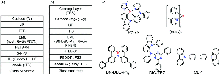
Fig. 1 shows the structure of (a) BE-PHOLEDs and (b) TE-PHOLED. Fig. 1(c) shows the materials used in the emitting layer (EML), namely, 4,4′-bis(carbazol-9-yl)biphenyl (CBP), 2,7-diphenyl-4b-aza-12b-boradibenzo[g,p]chrysene (BN-DBC-Ph2), 2,4-(diphenyl-6-bis(12-phenylindolo)[2,3-a]carbazol-11-yl)-1,3,5-triazine (DIC-TRZ), fac-tris(3-methyl-2-phenylpyridinato-N,C2′-)iridium(III) (Ir(mppy)3) and platinum(II)-2′-(3-methyl-imidazol-1-yl)-9-(pyridine-2-yl)-9H-2,9′-bicarbazole (PtN7N). The other organic materials used in PHOLED are shown as follows: 4,4′-bis[N-(1-naphthyl)-N-phenyl-amino]biphenyl (α-NPD), and 1,3,5-tris(N-phenylbenzimidazol-2-yl)benzene (TPBi). | ||
| Fig. 1 (a) Device structure of BE-PHOLED. (b) Device structure of TE-PHOLED. (c) Molecular structures of materials used in EML. | ||
Device fabrication and measurements
In this study, to evaluate suitable host materials for use in an efficient PHOLED with high color purity, BE-PHOLEDs were fabricated. The TE-PHOLED was fabricated to suppress the effect of vibrational structures of the emitter. First, glass substrates pre-coated with a 100 nm thin ITO layer with a sheet resistance of ∼20 Ω sq−1 were thoroughly cleaned by ultrasonication using some detergents and treated with UV ozone ambient. In BE-PHOLEDs, Clevios HIL 1.5 (∼30 nm) was spun onto the substrate. The film structures in the BE-PHOLEDs were as follows: α-NPD (20 nm)/HTEB-04 (10 nm)/host: 6 wt% PtN7N (20 nm)/TPBi (35 nm). After the formation of the organic layers, LiF (0.8 nm) and Al (100 nm) were deposited as the top electrodes. In the TE-PHOLEDs, a Ag–Pd–Cu (APC) alloy (100 nm, FURUYA METAL Co., Ltd) and ITO (10 nm) as the bottom electrode. Next, spinning on PEDOT: PSS (33 nm) and deposition of HTEB-04 (15 nm)/host: PtN7N (22 nm)/TPBi (20 nm) were carried out. After the formation of the organic layers, LiF (0.8 nm), MgAg (3 nm), and Ag (23 nm) were deposited as the top electrode. Organic layers were sequentially deposited on the substrate without breaking the vacuum at a pressure of approximately 10−5 Pa. Deposition rates for organic materials were 0.03 (dopant)–0.6 Å s−1; 0.1 Å s−1 for the LiF layer, and 1–4 Å s−1 for the top electrode. OLEDs were encapsulated using a UV epoxy resin and a glass cover under nitrogen after the formation of the top electrode. The EL spectra, luminance, and angular distribution characteristics were measured using a Keithley 2400 system equipped with a rotating sample stage and a Konica Minolta CS-2000 electroluminescence (EL) measurement system. The emission from BE-PHOLEDs was assumed to be isotropic such that the luminance was Lambertian, and the EQE was calculated from the luminance, current density, and EL spectra. On the other hand, the luminance of TE-PHOLED was not Lambertian; hence, the luminous efficiency and angular distribution characteristics are recorded at the front of the device.Definition of the parameters of the angular distribution characteristics
Δxy, which is the deviation of the angular color shift in the CIE 1931 (x, y) color coordinate, is defined as follows:Δxymax is the maximal deviation of the angular color shift in the CIE 1931 (x, y) color coordinate (up to 60°).
Results and discussion
PL spectra of PtN7N-doped films
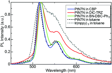
First, we evaluated the photoluminescence (PL) spectrum and quantum yield of the PtN7N-doped film with several hosts to clarify the composition of the EML suitable for demonstrating high-efficiency pure green-emitting devices. In recent years, the device characteristics of PHOLEDs have been reported to strongly depend on the host material. Several host materials suitable for demonstrating efficient green PHOLEDs have been reported, including boron-embedded polycyclic aromatics15,17 and TADF materials.16,18–21 Among these hosts, we selected BN-DBC-Ph215 and DIC-TRZ16 since the co-evaporation of exciplex-host and the dopant is relatively difficult. Table 1 summarizes the physical properties of the host materials and 6 wt% PtN7N-doped films, and Fig. 2 shows the PL spectrum of a 6 wt%-PtN7N-doped film. Also shown in Fig. 2 is the PL spectra of PtN7N and a conventional Ir complex Ir(mppy)3 in solution as reference. We see from Fig. 2 that PtN7N is more suitable for demonstrating pure green emission than Ir(mppy)3 since the PL spectrum of PtN7N is much narrower than that of Ir(mppy)3. However, the PL spectrum of PtN7N strongly depends on the host. Although the film of PtN7N-doped CBP and BN-DBC-Ph2 exhibits a PL spectrum similar to that in toluene, the film of PtN7N-doped DIC-TRZ exhibits a considerably broader emission spectrum. The observed broadening may be caused by the exciplex formation between PtN7N and DIC-TRZ. Su et al. have reported that exciplex emissions can be detected in the emitting layer,22 comprising a phosphorescent emitter and a host material with a small energy gap between the singlet and triplet excited states. Therefore, DIC-TRZ is not suitable for demonstrating PHOLED with high color purity. We fabricated PHOLEDs using CBP and BN-DBC-Ph2 as the host.| Host material | Material properties | PL properties in PtN7N-doped film | ||||
|---|---|---|---|---|---|---|
| μ e | μ h | E T | λ Peak | FWHMd | Φ PL | |
| a μ e and μh represent the electron and hole mobility (cm2 V−1 s−1), respectively. b E T represent the triplet energies (eV). c λ Peak. d FWHM. e Φ PL represent the peak emission wavelength (nm), full-width at half-maximum (nm), and PL quantum yield, respectively. | ||||||
| BN-DBC-Ph2 | 3.2 × 10⁻⁴ | 1.7 × 10⁻⁴ | 2.64 | 521 | 24 | 0.815 |
| CBP | 1.0 × 10⁻³ | 1.0 × 10⁻³ | 2.59 | 518 | 21 | 0.895 |
| DIC-TRZ | 1.4 × 10⁻³ | 1.4 × 10⁻³ | 2.68 | 520 | 50 | 0.430 |
Device performance of BE-PHOLEDs
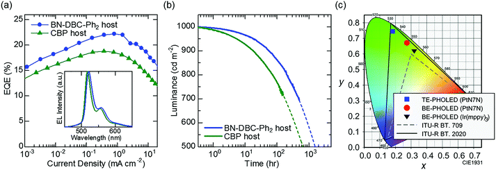
Fig. 3(a) shows the EQE–current density curves of the fabricated BE-PHOLED in each host material. A clear difference in the PHOLEDs is observed. Although the PLQY of PtN7N-doped CBP is higher than that of BN-DBC-Ph2, the EQE of PHOLED using BN-DBC-Ph2 is higher than that of PHOLED using CBP. The maximum EQE is >22%, corresponding to an internal quantum efficiency of ∼100%.23 To clarify the origin of host-dependent EQE, the molecular orientation of PtN7N was examined because the horizontal orientation of the transition dipole moments enhances the light outcoupling efficiency of OLEDs.24 We see from the X-ray absorption spectroscopy that PtN7N are randomly oriented in each host (details are shown in Fig. S1, ESI†). Thus, the difference in EQE between PHOLED using CBP and PHOLED using BN-DBC-Ph2 may originates from the difference in the carrier balance or confinement of the triplet excitons as in the case of Ir-based PHOLEDs.15The inset of Fig. 3(a) shows the EL spectrum of each BE-PHOLED. Spectral widths are similar to the PL spectrum width. A peak wavelength of 518 nm is observed for the BE-PHOLED using CBP, whereas that of 521 nm is observed for the BE-PHOLED using BN-DBC-Ph2. As the BT.2020 green primary is 532 nm, the PHOLED using BN-DBC-Ph2 is more favorable for demonstrating pure green emission. Fig. 3(b) shows the luminance as a function of the operating time of PHOLEDs using two hosts for an initial luminance of 1000 cd m−2. The operational stability of the PHOLED using BN-DBC-Ph2 is greater than that of the PHOLED using CBP, which corresponds to the result reported in a previous study using Ir(ppy)3 as the emitter.15 In addition, the stability of PtN7N is comparable to that of Ir(mppy)3 (Fig. S2, ESI†). Thus, PtN7N demonstrates promise for practical applications via the use of a suitable host and/or surrounding carrier transporting materials. Fig. 3(c) shows the difference in the CIE x–y coordinates between Ir(mppy)3 and PtN7N. An efficient green PHOLED with high color purity is observed using PtN7N and a suitable host material (Fig. 3(a) and (b)). However, the chromaticity of the PtN7N-based BE-PHOLED, with CIE x–y coordinates of (0.27, 0.67), is far from that of BT.2020 owing to the presence of vibrational structures observed at long wavelengths. The color purity of the PHOLED can be significantly improved via the suppression effect of the vibrational structures as the spectral half-width of the BE-PHOLED using BN-DBC-Ph2 is only 24 nm, which is comparable to that of the perovskite-LEDs.6
Improvement in color purity by using TE structures
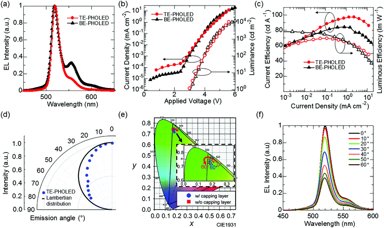
Our second challenge is to suppress the effect of the vibrational structures observed at wavelengths longer than that of the main emission peak (Fig. 3a) by utilizing microcavity resonance.25 However, as a side effect of microcavity resonance, spectral distortion according to change of viewing angles is also observed for the TE-PHOLEDs.26 The introduction of an organic capping layer on the top electrode is a possible solution. The capping layer is useful in that, by changing its optical thickness, the transmittance of the top electrode is changed, and the strength of the Fabry–Perot resonance effect, which is the optical multiple interference between the top and bottom metal electrodes, can be easily tuned.27,28 However, in a device with a strong cavity resonance, in several cases, the performance evaluated by the emission light of the front direction, including EQE or color purity, and stable viewing angle characteristics, are incompatible with each other.29 Therefore, TE-PHOLEDs that can suppress the angular color distortion while still maintaining benefits of color purity by using a capping layer are designed, with the maximum possible efficiency enhancement (details for Fig. S3, ESI†). Fig. 4(a) shows the EL spectrum of the fabricated TE-PHOLED. From the EL spectrum, the optimized microcavity structure is effective for reducing the effect of the vibrational structures. In addition, the spectral half-width of the optimized TE-PHOLED is 20 nm, which is narrower than that observed for BE-PHOLED. Fig. 3(a) (red square) shows the CIE x–y coordinates of the TE-PHOLED. The CIE x–y coordinates of the optimized TE-PHOLED reach (0.182, 0.742) at the front (at 0°). Assuming that the other two colors (red and blue) achieve the CIE x–y color coordinates of BT.2020, the CIE x–y color coordinates of the optimized PtN7N-based TE-PHOLED can cover 91% of the BT.2020 color space. On the other hand, the CIE x–y color coordinates of the Ir(mppy)3-based BE-PHOLED can cover only 67% of the BT.2020 color space.Fig. 4b shows the current and luminous efficiencies at the front of the optimized TE-PHOLED. A relatively high current efficiency of 98.8 cd A−1 and a luminous efficiency of 71.0 lm W−1 are observed for the optimized TE-PHOLED. Fig. 4(d), (e) and (f) show the viewing angle characteristics of the EL intensity, color coordinates, and EL spectrum, respectively. As the optical design was carried out so as to increase the color purity while suppressing the deterioration of the viewing angle characteristics, the optimized TE-PHOLED exhibits an extremely small color variation of Δxymax = 0.032 in the CIE 1931 coordinates according to the viewing angles 0° to 60°. In addition, the spectrum peak shift according to viewing angles of 0° to 60° is only 2 nm, hence, the optimized TE-PHOLED achieves high efficiency, high color purity, and high color stability. On the other hand, the angular distribution of the EL intensity with the viewing angle of the TE-PHOLED is narrower than the Lambertian distribution, which can be resolved by the introduction of a scattering capping layer.30
Conclusions
In summary, this work reports the development of an efficient green PHOLED with high color purity using PtN7N as the emitter and BN-DBC-Ph2 as the host material. The optimized BE-PHOLED exhibited a maximum EQE of >20% with CIE x–y coordinates of (0.27, 0.67). Then, a TE-PHOLED with a microcavity structure was optimized to suppress the effect of the vibrational structures. The CIE x–y coordinates of the optimized TE-PHOLED reached (0.18, 0.74) with a relatively high current efficiency of 98.8 cd A−1 and a small angular distribution of Δxymax = 0.032 in the CIE 1931 coordinates. As the emission spectrum of organic compounds is typically broad, QD and perovskite LEDs have been intensively examined in recent years with the aim of expanding the color reproduction area of displays. By contrast, the feasibility of an efficient green OLED with high color purity was demonstrated by using a suitable emitter and TE structure. The results of our experiment are expected to considerably contribute to the development of LEDs for displays with an expanded color reproduction area.Conflicts of interest
There are no conflicts to declare.Acknowledgements
The authors would like to thank JNC Petrochemical Corporation for providing BN-DBC-Ph2 and technical supports. The authors also would like to thank Kanto Chemical Co., Inc. for providing HTEB-04. This study was partially supported by a Grant-in-Aid for Scientific Research on Innovative Areas “π-System Figuration” (JP17H05164), the Iketani Science and Technology Foundation, and the Mitsubishi Foundation.Notes and references
- Recommendation ITU-R BT.2020-2, 2015.
- K. Masaoka, Y. Nishida, M. Sugawara and E. Nakasu, IEEE Trans. Broadcast., 2010, 56, 452 CrossRef.
- J. S. Steckel, J. Ho and S. Coe-Sullivan, Photonics Spectra, 2014, 48, 55 Search PubMed.
- B. O. Dabbousi and M. G. Bawendi, Appl. Phys. Lett., 1995, 66, 1316 CrossRef CAS.
- J. R. Manders, L. Qian, A. Titov, J. Hyvonen, J. T. Scott, J. Xue and P. H. Holloway, SID Int. Symp. Dig. Tech. Pap., 2015, 46, 73 CrossRef.
- S. Kumar, J. Jagielski, N. Kallikounis, Y.-H. Kim, C. Wolf, F. Jenny, T. Tian, C. J. Hofer, Y.-C. Chiu, W. J. Stark, T.-W. Lee and C.-J. Shih, Nano Lett., 2017, 17, 5277 CrossRef CAS PubMed.
- H. Cho, S. H. Jeong, M. H. Park, Y. H. Kim, C. Wolf, C. L. Lee and J. H. Heo, Science, 2015, 350, 1222 CrossRef CAS PubMed.
- S. Hosoumi, T. Yamaguchi, H. Inoue, S. Nomura, R. Yamaoka, T. Sasaki and S. Seo, SID Int. Symp. Dig. Tech. Pap., 2017, 48, 13 CrossRef CAS.
- Y. Kawamura, H. Kuma, M. Funahashi, M. Kawamura, Y. Mizuki, H. Saito, R. Naraoka, K. Nishimura, Y. Jinde, T. Iwakuma and C. Hosokawa, SID Int. Symp. Dig. Tech. Pap., 2011, 42, 829 CrossRef CAS.
- T. Hatakeyama, K. Shiren, K. Nakajima, S. Nomura, S. Nakatsuka, K. Kinoshita, J. Ni, Y. Ono and T. Ikuta, Adv. Mater., 2016, 28, 2777 CrossRef CAS PubMed.
- T. Fleetham, G. Li, L. Wen and J. Li, Adv. Opt. Mater., 2014, 26, 7116 CrossRef CAS PubMed.
- T. Fleetham, PhD thesis, Arizona State University, 2014, 116.
- H. Fukagawa, T. Shimizu, H. Hanashima, Y. Osada, M. Suzuki and H. Fujikake, Adv. Mater., 2012, 24, 5099 CrossRef CAS PubMed.
- Q. Wang, Z. Deng and D. Ma, Appl. Phys. Lett., 2009, 94, 233306 CrossRef.
- S. Hashimoto, T. Ikuta, K. Shiren, S. Nakatsuka, J. Ni, M. Nakamura and T. Hatakeyama, Chem. Mater., 2014, 21, 6265 CrossRef.
- D. Zhang, L. Duan, C. Li, Y. Li, H. Li, D. Zhang and Y. Qiu, Adv. Mater., 2014, 26, 5050 CrossRef CAS PubMed.
- H. Hirai, K. Nakajima, S. Nakatsuka, K. Shiren, J. Ni, S. Nomura, T. Ikuta and T. Hatakeyama, Angew. Chem., Int. Ed., 2015, 54, 13581 CrossRef CAS PubMed.
- H. Fukagawa, T. Shimizu, T. Kamada, Y. Kiribayashi, Y. Osada, M. Hasegawa, K. Morii and T. Yamamoto, Adv. Opt. Mater., 2014, 2, 1070 CrossRef CAS.
- D. Zhang, L. Duan, D. Zhang and Y. Qiu, J. Mater. Chem. C, 2014, 2, 8983 RSC.
- H. Fukagawa, T. Shimizu, T. Kamada, S. Yui, M. Hasegawa, K. Morii and T. Yamamoto, Sci. Rep., 2015, 5, 9855 CrossRef CAS PubMed.
- H. Fukagawa, T. Shimizu, Y. Iwasaki and T. Yamamoto, Sci. Rep., 2017, 7, 1735 CrossRef PubMed.
- S.-J. Su, C. Cai, J. Takamatsu and J. Kido, Org. Electron., 2012, 13, 1937 CrossRef CAS.
- Z. B. Wang, M. G. Helander, J. Qiu, D. P. Puzzo, M. T. Greiner, Z. M. Hudson, S. Wang, Z. W. Liu and Z. H. Lu, Nat. Photonics, 2011, 5, 753 CrossRef CAS.
- D. Yokoyama, J. Mater. Chem., 2011, 21, 19187 RSC.
- N. Takada, T. Tsutsui and S. Saito, Appl. Phys. Lett., 1993, 63, 2032 CrossRef CAS.
- C.-L. Lin, H.-C. Chang, K.-C. Tien and C.-C. Wu, Appl. Phys. Lett., 2007, 90, 071111 CrossRef.
- R. H. Jordan, A. Dodabalapur and R. E. Slusher, Appl. Phys. Lett., 1996, 69, 1997 CrossRef CAS.
- E. Kim, J. Chung, J. Lee, H. Cho, N. S. Cho and S. Yoo, Org. Electron., 2017, 48, 348 CrossRef CAS.
- Q. Huang, K. Walzer, M. Pfeiffer, K. Leo, M. Hofmann and T. Stübinger, J. Appl. Phys., 2006, 100, 064507 CrossRef.
- T. W. Canzler, S. Murano, D. Pavicic, O. Fadhel, C. Rothe, A. Haldi, M. Hofmann and Q. Huang, SID Int. Symp. Dig. Tech. Pap., 2011, 42, 975 CrossRef CAS.
Footnote |
| † Electronic supplementary information (ESI) available: Results of XAS, operational stability, results of optical simulation, energy level diagram and color shift with applied voltage. See DOI: 10.1039/c7qm00588a |
| This journal is © the Partner Organisations 2018 |


