
Homologous Co3O4‖CoP nanowires grown on carbon cloth as a high-performance electrode pair for triclosan degradation and hydrogen evolution†
Chaojie
Lyu
a,
Jinlong
Zheng‡
 a,
Rui
Zhang
a,
Ruqiang
Zou
b,
Bin
Liu
c and
Wei
Zhou
*a
a,
Rui
Zhang
a,
Ruqiang
Zou
b,
Bin
Liu
c and
Wei
Zhou
*a
aSchool of Chemistry, Beihang University, Beijing 100191, China. E-mail: zhouwei@buaa.edu.cn
bBeijing Key Laboratory for Theory and Technology of Advanced Battery Materials, Department of Materials Science and Engineering, College of Engineering, Peking University, Beijing 100871, China
cInstitute for Food & Bioresource Engineering, College of Engineering, Peking University, Beijing 100871, China
First published on 11th December 2017
Abstract
As a widely used antimicrobial agent in toothpastes and body washes for decades, triclosan (TCS) is causing great harm to the environment through wastewater. Herein, we used a two-electrode system to remove TCS comprising Co3O4 nanowires/carbon cloth (Co3O4 NWs/CC) as anode and CoP nanowires/carbon cloth (CoP NWs/CC) as cathode. At a constant current density of 10 mA cm−2, the degradation efficiency for TCS is 95% in 60 min and it is transformed into important chemical raw materials, including phenol, 1,2-dihydroxybenzene, and 2-phenoxyphenol. Subsequently, hydrogen is generated on the CoP NWs/CC cathode with Faradaic efficiency of nearly 100%. The synergetic effect of the superhydrophilic surfaces of the Co3O4 NWs/CC anode and the CoP NWs/CC cathode as well as the superaerophobicity of the cathode assures full contact of the electrolyte solution and the active materials and high-efficiency generation of H2 bubbles.
 Wei Zhou | Dr Wei Zhou received her PhD degree in Materials Science and Engineering from Beihang University under the supervision of Prof. Lin Guo in 2009. She once worked as a visiting scholar in Prof. Hong Yang's group in University of Illinois at Urbana-Champaign (UIUC) in 2012–2013. Currently, she is a professor at School of Chemistry in Beihang University. Her research interests focus on iron triad (Fe, Co, Ni) and their compounds’ nanomaterials for applications in energy, adsorption and catalysis. |
Introduction
As an antimicrobial agent, triclosan (TCS, 5-chloro-2-(2,4-dichlorophenoxy)-phenol) has been added to many consumer products, such as toothpastes, soaps, body washes, detergents, and surgical cleaning treatments, for decades.1 It has been reported that over 100 tons of TCS enters municipal wastewater treatment plants in the U.S. every year, about half of which remains in the streams with little removal under anaerobic digestion.2 Unfortunately, mass residue has been detected in effluents, biosolids, and even in human breast milk.3 Recently, the U.S. Food and Drug Administration (FDA) decided that TCS cannot be treated as GRAS for use in consumer antiseptic wash products due to lack of sufficient information.4 Moreover, the potential risk for the environment worries many people as TCS can transform into the more toxic and persistent pollutant, viz., chlorodioxin.5 Thus, it is urgent to develop an efficient TCS degradation method for wastewater treatment.Various methods have been used to degrade TCS, including ozonation, biological treatment, photolysis, oxidizer oxidation, and electrochemical processes. Among them, the ozonation technique, biological treatment, and photolysis technique are hindered by high cost, prolonged degradation time, and secondary pollution.6–10 The chemical oxidants, such as KMnO4, K2FeO4, and S2O82−, can degrade TCS effectively, but they make the treated water coloured and generate sludge.11–14 The simple and flexible electrochemical process has attracted much attention as it is low cost and highly efficient.15,16 For instance, Niu et al. fabricated the Ti/SnO2–Sb/Ce–PbO2 anode and obtained a high degradation rate of 99.9% during 5 min at 2–10 mA cm−2 with pH = 3–11.15 However, some chlorinated intermediates including 2,4-dichlorophenol, 5-chloro-3-(chlorohydroquinone)phenol, and 2-chloro-5-(2,4-dichlorophenoxy)benzene-1,4-diol were produced, which might cause reproductive toxicity, neurotoxicity, and endocrine system disturbance. Alternatively, Wang et al. used a boron doped diamond film electrode and TCS was completely oxidized to CO2 at current density above 2 mA cm−2 with increase in electrolysis time.16 Therefore, it is very important to develop suitable electrodes to achieve high-efficiency degradation with intermediates of nonchlorinated organic compounds.16,17
Moreover, electrocatalytic water splitting has been recognized as an ideal approach to produce clean H2 fuel to replace fossil fuels.18 However, the hydrogen evolution reaction (HER) and the oxygen evolution reaction (OER) of water splitting require efficient electrocatalysts to reduce the electrical energy consumption.19 At present, some transition metal phosphides, sulphides, and selenides have been reported as having promising HER catalytic performances,20–22 while some transition metal oxides, nitrides, and hydroxides exhibit attractive OER activities.23–25 Herein, we choose homologous cobalt compounds as electrocatalysts to realize energy-saving hydrogen production at cathode and TCS degradation at anode. Moreover, the electro-oxidation of TCS might reduce the bottleneck of the OER process, similar to the reported addition of methanol, ethanol, glycerol, hydrazine, and urea.26–30 Thus far, the bi-functional system has not been reported using homologous cobalt compounds as electrode materials. Notably, the degradation products of TCS are valuable chemical raw materials, including phenol, 1,2-dihydroxybenzene, and 2-phenoxyphenol, instead of chlorinated products.
Results and discussion
The precursor of Co(CO3)0.5OH·0.11H2O nanowires (NWs) in diameters of about 100–200 nm with an orthorhombic structure was prepared on carbon cloth (precursor/CC) by a hydrothermal method (Fig. S1, ESI†).31 The corresponding CoP and Co3O4 NWs on carbon cloth (CC) with similar morphologies were obtained through low-temperature phosphidation and heat treatment processes, respectively. Their components were confirmed by XRD patterns and EDX spectrum shown in Fig. S2 and S3 (ESI†). The morphological and structural characterization of CoP NWs/CC and Co3O4 NWs/CC are shown in Fig. 1. As shown in Fig. 1a and c, the CoP and Co3O4 microflowers assembled by NWs ∼100 nm in diameter were grown uniformly on CC. Single CoP and Co3O4 NWs composed of numerous tiny particles were confirmed by TEM as shown in Fig. 1b and d, respectively. Their corresponding HRTEM images showed lattice spacings of 0.23 and 0.29 nm, corresponding to the (201) planes of CoP and the (220) planes of Co3O4. In addition, the sample of Co3O4 octahedron/CC (Co3O4 Oct/CC) was prepared for comparison by a hydrothermal method (see Experimental) with related characterizations in Fig. S4 (ESI†). | ||
| Fig. 1 (a) SEM image of CoP NWs/CC with magnified CoP NWs inseted. (b) TEM image of a single CoP NW with corresponding HRTEM inseted. (c) SEM image of Co3O4 NWs/CC with magnified Co3O4 NW insetted. (d) TEM image of a single Co3O4 NW with corresponding HRTEM image insetted. | ||
Fig. 2 shows the X-ray photoelectron spectroscopy (XPS) results of the CoP (Fig. 2a and b) and the Co3O4 (Fig. 2c and d). As shown in Fig. 2a, the peaks at 778.4 and 793.7 eV could be assigned to Co 2p3/2 and Co 2p1/2 from CoP, while those at 781.1 and 796.6 eV could be indexed to Co 2p3/2 and Co 2p1/2 from oxidized Co species.32,33 The oxidized Co might be arising from superficial oxidation due to contact with air.33 In Fig. 2b, the P 2p signal showed two main peaks at 129.7 and 130.8 eV, corresponding to P 2p3/2 and P 2p1/2 from CoP, while the broad peak at 134.2 eV could be assigned to oxidized phosphate species on the surface of the sample.34 The XPS results of CoP/CC were in agreement with the XRD pattern (Fig. S2, ESI†), despite slight oxidation of the surface. Fig. 2c shows the Co 2p XPS spectra of the Co3O4 sample. The peaks at 779.8 and 795.0 eV could be assigned to Co(II), while the peaks at 781.5 and 796.8 eV to Co(III), which implies the formation of Co3O4.35Fig. 2d shows the XPS spectra of the O 1s, which could be deconvoluted into three peaks. The smaller binding energy peak at 529.5 eV could be ascribed to Co–O species,35 while the other two peaks located at 530.9 and 532.0 eV are consistent with the adsorbed oxygen species.36 The XPS results of Co3O4/CC were in accordance with the XRD characterization (Fig. S3, ESI†).
 | ||
| Fig. 2 High-resolution XPS spectra of (a) Co 2p and (b) P 2p for CoP. High-resolution XPS spectra of (c) Co 2p and (d) O 1s for Co3O4. | ||
We then examined the HER activity of the CoP NWs/CC with a scan rate of 2 mV s−1 using a three-electrode electrochemical station in 0.5 M H2SO4 solution (pH = 0), 1 M PBS buffer solution (pH = 7), and 1 M KOH solution (pH = 14), separately. Fig. 3a shows the linear sweep voltammetry (LSV) curves vs. the reversible hydrogen electrode (RHE). The overpotential for a current density of 10 mA cm−2 is an important parameter for OER because it represents the current density from a realistic device with 12% solar to hydrogen efficiency.37 As shown in Fig. 3a, the overpotentials at the current density of −10 mA cm−2 were 118 mV (pH = 0), 130 mV (pH = 7) and 69 mV (pH = 14). According to the results, the CoP NWs/CC showed best HER performance in alkaline condition. The HER kinetics of the CoP NWs/CC were examined by Tafel plots (η vs. log|j|) derived from LSV. The linear regions of the Tafel plots were fitted via the Tafel equation (η = b × log|j| + a, where η is the overpotential, b is the Tafel slope, and j is the current density). Fig. 3b shows the Tafel slopes of 73, 144 and 70 mV dec−1 for CoP NWs/CC at pH values of 0, 7 and 14, respectively. Recently reported Co-based HER catalysts in solution with pH = 0, 7, and 14 are summarized in Table S1 (ESI†). The HER performance of CoP NWs/CC in H2SO4 solution (pH = 0) and PBS buffer solution (pH = 7) was comparable to some reported Co-based catalysts. However, the HER performance of the CoP NWs/CC in KOH solution (pH = 14) with overpotential of 69 mV was superior to most reported Co-based catalysts (overpotentials higher than 100 mV). It is well known that high stability and durability are necessary for the application of electrocatalysts. Thus, chronopotentiometry tests at a current density of −10 mA cm−2 were performed to confirm the stability of the CoP NWs/CC (Fig. 3c). The CoP NWs/CC showed initial potentials of −0.32, −0.74, and −1.09 V with retention of 98.6%, 95.5%, and 98.4% after 24 h at pH = 0, 7, and 14, respectively. Considering the overpotential, Tafel slope and stability, the CoP NWs/CC exhibited better HER performance in KOH solution than in H2SO4 solution and PBS buffer solution. Fig. 3d shows the overpotential and potential retention of our study in comparison with other reported Co-based catalysts in KOH solution. The details are also summarized in Table S1 (ESI†). From data shown in Fig. 3d and Table S1 (ESI†), it could be inferred that the CoP NWs/CC exhibited excellent HER performance with lower overpotential of 69 mV and higher potential retention of 98.4% than other catalysts,38–44 which may be attributed to the superhydrophilic and superaerophobic property of CoP NWs/CC (Fig. S5, ESI†).45,46 The superhydrophilic surface ensured full contact of the CoP NWs/CC electrode with the electrolyte solution during water splitting, while the superaerophobic property reduced gas bubble adhesion and made H2 bubbles leave quickly from surfaces of the CoP NWs/CC.47,48 The superficial characters of the CoP NWs/CC significantly improved the efficiency of H2 generation, showing excellent HER performance.
 | ||
| Fig. 3 (a) LSV curves of CoP NWs/CC for HER at pH values of 0, 7, and 14 with a scan rate of 2 mV s−1. (b) Corresponding Tafel plots of CoP NWs/CC for HER at pH values of 0, 7, and 14. (c) Chronopotentiometry technology at a constant current density of −10 mA cm−2 of CoP NWs/CC cathode at pH values of 0, 7, and 14. (d) Comparison of the overpotential and potential retention of our work with recent reported works. | ||
Both TCS degradation and OER test were carried out in 1 M KOH solution under a three-electrode system, using the Co3O4 NWs/CC as the working electrode, Pt wire as counter electrode, and saturated Ag/AgCl electrode as reference electrode. Fig. S5a (ESI†) shows the LSV curves with and without TCS under the three-electrode system. Clearly, OER process would compete with the oxidation of TCS through the electrocatalytic degradation.49 In the absence of TCS, the Co3O4 NWs/CC required an overpotential of 360 mV to achieve a current density of 10 mA cm−2 in 1 M KOH solution, which was comparable to some previously reported Co3O4 electrocatalysts, such as Co3O4 nanoflakes,50 Co3O4 film51 and Co3O4/rGO composite.52 Upon the addition 40 mg L−1 TCS, the corresponding overpotential decreased to 310 mV, indicating that the TCS degradation was easier than OER process using the Co3O4 NWs/CC anode. The corresponding Tafel slopes are shown in Fig. S5b (ESI†). The Tafel slope was 123 mV dec−1 for Co3O4 NWs/CC in 1 M KOH solution with TCS, which was superior to that without TCS (140 mV dec−1), suggesting more favorable kinetics to drive large current density at low overpotential with TCS addition.53 To determine the impact of the additional TCS on HER performance of the CoP NWs/CC, we evaluated the HER performance with and without TCS in 1 M KOH solution under three-electrode system. As demonstrated in Fig. S6 (ESI†), the LSV curves of the CoP NWs/CC for HER with and without TCS almost overlapped and the Tafel slopes were nearly equal, implying that the added TCS showed no evident negative impact on HER in the CoP NWs/CC cathode.
Since the excellent HER and TCS degradation performance in 1 M KOH solution with TCS, we assembled a two-electrode electrolyzer with Co3O4 NWs/CC as anode and CoP NWs/CC as cathode (Co3O4 NWs/CC‖CoP NWs/CC) in a KOH solution with and without TCS (Fig. 4a). We chose Co3O4 as anode active material due to its excellent OER performance as reported before.54–58 Based on the excellent HER performance of CoP NWs/CC in alkaline condition, it was selected as cathode. We further confirmed the competitive result of TCS degradation and OER process at the anode as the LSV data show in Fig. 4b.49 Without TCS, the cell requires a voltage of 1.68 and 1.76 V to achieve current density of 10 and 20 mA cm−2 in 1 M KOH solution, respectively. Adding TCS with concentration of 40 mg L−1, it only needed potentials of 1.63 and 1.70 V, respectively, implying a much higher energy conversion efficiency of TCS degradation than oxygen generation. According to this LSV result, we degraded TCS by chronopotentiometry at a current density of 10 mA cm−2 using the Co3O4 NWs/CC‖CoP NWs/CC electrode pair (Fig. 4c). The Co3O4 Oct/CC and the hydrophilic bare CC (treated by HNO3) were also tested as anodes under the same conditions for comparison. As shown in Fig. 4c, the degradation rates were 95%, 82% and 52% in 60 min using the Co3O4 NWs/CC‖CoP NWs/CC, the Co3O4 Oct/CC‖CoP NWs/CC and the CC‖CoP NWs/CC electrode pairs, respectively. The concentration change of TCS by HPLC in the degradation process is shown in Fig. S7 (ESI†). The electrochemical degradation of TCS has attracted much attention in recent years.59–63 For example, a degradation rate of 62% was obtained in 180 min using a boron-doped diamond electrode. However, it worked at a high current density of 28.5 mA cm−2 and a low TCS concentration (1.19 mg L−1).59 Using the Ti/SnO2–Sb/Ce–PbO2 anode, TCS degradation rate of 99.9% was achieved at 10 mA cm−2 in 5 min, but the TCS concentration was only 4 mg L−1.15 As exhibited in Table S2 (ESI†), most studies could realize decent degradation results in a low TCS concentration, but were incapable in a relatively high concentration. Compared with these reported results, the high degradation concentration (40 mg L−1) and degradation rate (95%), short degradation time (60 min) and easily assembled Co3O4 NWs/CC‖CoP NWs/CC pair provide the possibility for practical application of TCS degradation. In addition, the Co3O4 NWs/CC‖CoP NWs/CC pair could also produce H2 in the degradation process. For the Co3O4 NWs/CC‖CoP NWs/CC, the Faradaic efficiency of H2 evolution on cathode was calculated by comparing the gas amount experimentally quantified with that theoretically calculated. As shown in Fig. S8 (ESI†), the measured amount effectively matched the calculated amount based on the passed charge, suggesting a Faradaic efficiency close to 100%.49 Considering the practical application, we further explored the stability and cyclability of TCS degradation and H2 generation by the Co3O4 NWs/CC‖CoP NWs/CC pair. We repeated a two-hour chronopotentiometry electrolysis for 6 cycles. As shown in Fig. 4d, the TCS degradation rates were 100%, 98.2%, 97.0%, 96.3%, 95.4%, and 94.3%, in sequence, using Co3O4 NWs/CC anode. Moreover, there was no apparent decrease in H2 Faradaic efficiency in the CoP NWs/CC cathode simultaneously. Before and after 6 successive electrolysis cycles, optical photos of the CoP NWs/CC and the Co3O4 NWs/CC (Fig. S9, ESI†) indicated the stability of the active materials grown on CC. The SEM images of the CoP NWs/CC and the Co3O4 NWs/CC in Fig. S10a and b (ESI†) show that there was no visible change in morphology and structure after 6 successive electrolysis cycles. The XRD patterns in Fig. S10c and d (ESI†) show that the CoP NWs/CC and the Co3O4 NWs/CC, after 6 cycles, had the same components as their separate initial electrodes. In addition, the XPS spectra of the CoP and the Co3O4 samples after 6 cycles indicated there was no remarkable component change for the two electrodes compared with their separate initial electrodes (Fig. S11, ESI†). The above results illustrate that the Co3O4 NWs/CC‖CoP NWs/CC pair show excellent stability and cyclability for TCS degradation and H2 generation.
 | ||
| Fig. 4 (a) Schematic illustration for TCS degradation and H2 generation by a Co3O4 NWs/CC‖CoP NWs/CC pair. (b) LSV curves of water electrolysis for the Co3O4 NWs/CC‖CoP NWs/CC pair with a scan rate of 2 mV s−1 with and without TCS. (c) Degradation rates of TCS with different anodes at the current density of 10 mA cm−2. (d) TCS degradation rates and H2 Faradaic efficiencies of Co3O4 NWs/CC‖CoP NWs/CC pair in 1 M KOH solution with 40 mg L−1 TCS for 6 successive electrolysis cycles. | ||
To test for a better performance of the Co3O4 NWs/CC than the Co3O4 Oct/CC and the bare CC anodes, the effect of wettability on degradation efficiency was studied in Fig. 5. The different wettability was checked by measuring the contact angles of TCS solution towards different electrode surfaces. Fig. 5a represents the optical photo of Co3O4 NWs/CC with a smooth and dry surface before the test. Fig. 5b shows the Co3O4 NWs/CC surface adsorbing a liquid drop with a contact angle of 0°, indicating the superhydrophilic property of the surface.44,45 However, the liquid contact angle of Co3O4 Oct/CC surface is about 15.5° in Fig. 5c, proving its surface was highly hydrophilic. The hydrophilicity varies along with the surficial morphologies of the Co3O4 micro/nanostructures, that is, the flower-like structure composed of nanowires from Co3O4 NWs/CC showed better hydrophilic property than octahedrons from Co3O4 Oct/CC. Although the hydrophilic property of the CC improved from contact angle of 140.2° (Fig. S12, ESI†) to 95.7° (Fig. 5d) by HNO3 treatment, it was still poorer than the electrodes covered by Co3O4 NWs or octahedrons.
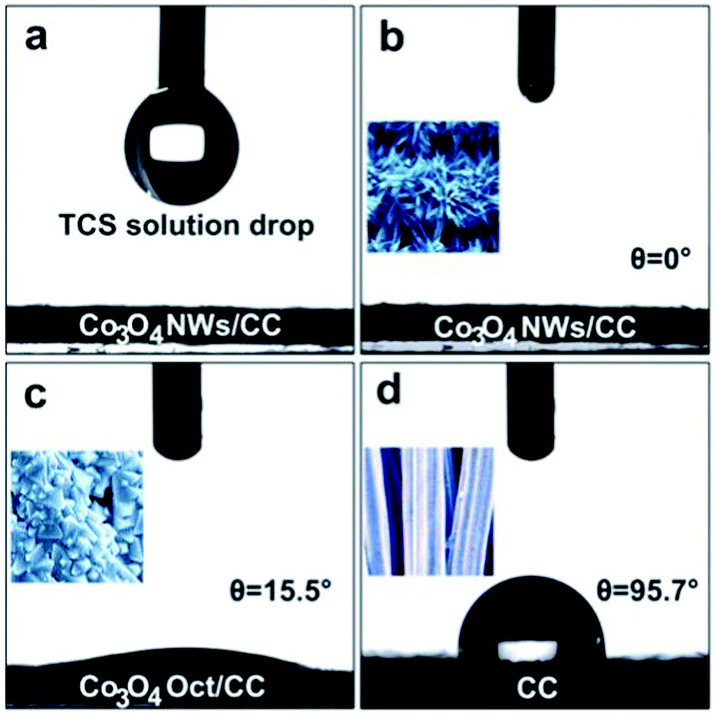 | ||
| Fig. 5 (a) Co3O4 NWs/CC surface before wettability test. Co3O4 NWs/CC (b), Co3O4 Oct/CC (c), and HNO3-treated bare CC (d) with liquid contact angle of 0°, 15.5°, and 95.7°, respectively. The insets show their corresponding surficial morphologies. | ||
Comparing the wettability results, the Co3O4 NWs/CC exhibited the best hydrophilicity among the three anodes, owing to its typical 3D architecture with rough surface. It could be inferred that when the Co3O4 NWs/CC was immersed into TCS solution, the solution could easily diffuse into the electrode. In this case, sufficient contact of TCS molecules with the active components on the electrode was guaranteed, leading to an excellent degradation efficiency.46 Owing to its weaker hydrophilicity, the Co3O4 Oct/CC showed poorer degradation than the Co3O4 NWs/CC (Fig. 4c). For the bare CC, the electrolyte solution could not wet the surface completely and only limited TCS molecules could contact the CC surface. In addition, the CC also showed negligible catalytic ability for TCS degradation. Simultaneously, the superhydrophilicity of the CoP NWs/CC cathode also assured that the electrolyte solution wet the surficial active materials thoroughly and the superaerophobicity enabled H2 bubbles to generate efficiently and release rapidly (Fig. S13, ESI†). Therefore, the combination of the Co3O4 NWs/CC anode and the CoP NWs/CC cathode achieved high-efficiency TCS degradation and hydrogen generation with suitable morphologies providing optimal wettability.
The electrochemical degradation mechanism was proposed based on the intermediates identified by the technique of liquid chromatograph-mass spectrometer (LC-MS). Three main peaks at m/z 186, m/z 110, and m/z 94 were identified from the MS derived from TCS degradation. The details are shown in Table S2 (ESI†). According to the three detected intermediates and their changes with respect to retention time, two main pathways of TCS degradation were proposed as illustrated in Fig. 6. The dechlorination process in path 1 led to the first intermediate of 2-phenoxyphenol (m/z 186). Then, the 2-phenoxyphenol would be further degraded in two different pathways, including C–O–C bond-breaking following path 2a with product of phenols (m/z 94), and following path 2b with products of benzene and 1,2-dihydroxybenzene (m/z 110). Both of these intermediates from the two pathways would be further oxidized through ring opening reactions and then degraded into water and carbon dioxide, followed by mineralization. Clearly, the intermediates obtained in our proposed system show lower toxicity and less harm to the human body and plants compared to chlorinated intermediate products. Notably, these phenols are important chemical raw materials with a wide range of organic synthetic applications in fibres, rubber, plastics, pharmaceuticals, pesticides, spices, dyes, and coatings.
 | ||
| Fig. 6 Probable degradation pathways of TCS on the Co3O4 NWs/CC anode. | ||
Conclusions
In summary, we have demonstrated a facile strategy for triclosan degradation and H2 production effectively using the Co3O4 NWs/CC as anode and the CoP NWs/CC as cathode under a two-electrode system. The degradation efficiency of TCS at the anode is 95% in 60 min and the Faradaic efficiency of H2 production at the cathode is nearly 100%. Compared to chlorinated organic compounds, the degradation products are important chemical raw materials, including phenol, 1,2-dihydroxybenzene, and 2-phenoxyphenol. As the anode, the liquid contact angle of Co3O4 NWs/CC is about 0°, much smaller than those of Co3O4 Oct/CC (∼15.5°) and bare CC (∼95.7°). The superhydrophilicity of Co3O4 NWs/CC makes the TCS solution fully contact the electrode surfaces easily, leading to an excellent degradation efficiency. In addition, the superhydrophilicity and superaerophobicity of the CoP NWs/CC cathode assures full contact of electrolyte solution with superficial active materials and more efficient H2 generation. Given the low cost and excellent cycling stability of the catalysts and the high efficiency of TCS degradation and H2 production, this study would open a new opportunity towards the development of an electrochemical water splitting system for energy-saving hydrogen generation and high-efficiency TCS degradation. It might provide a feasible route to treat the large amounts of TCS now existing in the aquatic ecosystem in the future.Experimental
Materials
CoCl2·6H2O was purchased from Guangdong Guanghua Sci-tech Co., Ltd. Urea, Na2SO4, NaH2PO2·H2O, and Co(NO3)2·6H2O were purchased from Beijing Chemical Works. NH4F and cetyltrimethyl ammonium bromide (CTAB) were purchased from Aladdin Ltd, Shanghai, China. NaH2PO4 and Na2HPO4 were used for preparation of PBS buffer solution. TCS was purchased from Sigma-Aldrich (USA). H2SO4 solution and NaOH were used to change the pH of the electrolyte. All chemicals were used as received. Carbon cloth was provided by Shanghai Hesen Electric Co., Ltd. The deionized (DI) water used throughout all experiments was purified through a Millipore system. HPLC-grade acetonitrile was used for sample analyses.Preparation of precursor/CC, CoP NWs/CC cathode and Co3O4 NWs/CC anode
A piece of carbon cloth (CC, 2 × 3 cm2) was immersed into concentrated HNO3 for 24 h to remove surficial impurities, followed by washing with deionized water and ethanol. In a typical synthesis, CoCl2·6H2O (0.30 g), NH4F (0.095 g), and urea (0.30 g) were mixed in 20 mL DI water under stirring for 20 min until complete dissolution. The solution was then transferred into a Teflon-lined stainless autoclave (25 mL), and the CC was immersed into the solution. The autoclave was sealed and maintained at 120 °C for 6 h in an oven. After the autoclave cooled down naturally, the precursor/CC was taken out and washed with water and ethanol several times, then dried at 60 °C for 5 h. To prepare the CoP NWs/CC cathode, the precursor/CC and NaH2PO2·H2O (300 mg) were placed at two separate positions in a porcelain boat with NaH2PO2·H2O at the upstream side of the furnace. Subsequently, the samples were heated at 300 °C for 2 h at a heating rate of 2 °C min−1 in a N2 atmosphere and then, naturally cooled to ambient temperature under N2. The CoP NWs/CC was finally obtained. The Co3O4 NWs/CC was obtained by annealing the precursor/CC at 300 °C for 2 h in a N2 atmosphere and then, cooled down to ambient temperature under N2.Preparation of Co3O4 Oct/CC anode
Co(NO3)2·6H2O (0.30 g) and CTAB (0.15 g) were dissolved in a mixture of 4 mL of DI water and 32 mL of methanol. After sonication for 30 min, the resultant solution was then transferred to 50 mL Teflon autoclaves and the CC was immersed in the solution for 30 min. Then, the Teflon autoclaves were heated in an oven at 180 °C for 12 h. After the autoclave cooled down slowly to room temperature, the sample was taken out and washed with DI water and ethanol several times, then dried at 60 °C.Characterizations
The morphologies of the samples were studied using a field-emission gun scanning electron microscope (SEM, Hitachi 7500). Transmission electron microscopy (TEM) investigations were carried out using a JEOL JEM-2100F microscope. X-ray diffraction (XRD) spectra of the samples were recorded by a Rigaku Dmax 2200 X-ray diffractometer (XRD) with Cu-Kα radiation (λ = 1.5416 Å). X-ray photoelectron spectroscopy (XPS) measurements were performed on an ESCALAB 250 photoelectron spectrometer. The concentrations of the TCS were quantified by HPLC (Agilent 1260 series) equipped with a C18 column (Agilent Technology) using a gradient composition of acetonitrile and water (volume ratio of 70![[thin space (1/6-em)]](https://www.rsc.org/images/entities/char_2009.gif) :30) at a constant flow rate of 1 mL min−1 and UV detector of 220 nm. Under these conditions, the retention time of TCS was 5.2 min. The intermediate products were analyzed by liquid chromatograph-mass spectrometer (LC-MS, Waters Xevo TQ-S Micro). High performance liquid chromatography (HPLC) was performed on a reverse phase liquid chromatographic column (Waters Xterra 5 μm MS C18 column) using a Waters 2695 XE LC instrument (Waters Corp., Milford, MA) and flowing phase of acetonitrile, water (70:30) and acetic acid (0.1%) at a constant flow rate of 0.5 mL min−1. Atmospheric pressure ionization tandem mass spectrometry analysis was performed on a benchtop triple quadrupole mass spectrometer operated using a negative electrospray ionization source. The surface wettability of the electrodes was characterized using a KSV CAM200 Goniometer instrument at ambient temperature in air. The liquid contact angles were determined by averaging measurements taken from at least five different positions on the measured surfaces.
:30) at a constant flow rate of 1 mL min−1 and UV detector of 220 nm. Under these conditions, the retention time of TCS was 5.2 min. The intermediate products were analyzed by liquid chromatograph-mass spectrometer (LC-MS, Waters Xevo TQ-S Micro). High performance liquid chromatography (HPLC) was performed on a reverse phase liquid chromatographic column (Waters Xterra 5 μm MS C18 column) using a Waters 2695 XE LC instrument (Waters Corp., Milford, MA) and flowing phase of acetonitrile, water (70:30) and acetic acid (0.1%) at a constant flow rate of 0.5 mL min−1. Atmospheric pressure ionization tandem mass spectrometry analysis was performed on a benchtop triple quadrupole mass spectrometer operated using a negative electrospray ionization source. The surface wettability of the electrodes was characterized using a KSV CAM200 Goniometer instrument at ambient temperature in air. The liquid contact angles were determined by averaging measurements taken from at least five different positions on the measured surfaces.
Electrocatalytic measurements
HER measurements were performed on Gamry Interface 1000 electrochemical workstation with a three-electrode system. The CoP NWs/CC (1 × 1 cm2), a graphite electrode, and a saturated Ag/AgCl electrode were used as the working electrode, the counter electrode, and the reference electrode, respectively. The Ag/AgCl electrode could be converted to the reversible hydrogen electrode (RHE) scale by adding a value of (0.197 + 0.0591 × pH) V. The linear sweep voltammetry (LSV) measurements of HER were conducted in 0.5 M H2SO4 solution (pH = 0), 1 M PBS buffer solution (pH = 7), and 1 M aqueous KOH solution (pH = 14) separately at a scan rate of 2 mV s−1. The OER measurements were conducted at a scan rate of 2 mV s−1 in 1 M KOH solution with and without TCS under a three-electrode system with saturated Ag/AgCl as the reference electrode and Pt wire as the counter electrode. The overall water splitting was performed using the Co3O4 NWs/CC‖CoP NWs/CC pair in 1 M KOH solution with and without TCS at a scan rate of 2 mV s−1. The degradation of TCS was also performed on Gamry Interface 1000 electrochemical workstation in a two-electrode system with the Co3O4 NWs/CC (2 × 3 cm2) as the anode and the CoP NWs/CC (2 × 3 cm2) as the cathode. Hydrogen generated from the cathode was collected by gas drainage set with inverted cylinder filled with TCS degradation solution and the CoP NWs/CC electrode at the bottom of the cylinder during the degradation process. The Faradaic efficiency was calculated by comparing the amount of measured with calculated hydrogen.Degradation of TCS
The degradation of TCS was performed with a two-electrode system. The CoP NWs/CC (2 × 3 cm2) was used as the cathode and the Co3O4 NWs/CC (2 × 3 cm2) as the anode. The degradation solution was 1 M KOH with the TCS concentration of 40 mg L−1. The solution of TCS in the reactor was stirred continuously using a magnetic stirrer. The degradation process was carried out by chronopotentiometry with a current density 10 mA cm−2.Conflicts of interest
There are no conflicts to declare.Acknowledgements
This work was financially supported by National Natural Science Foundation of China (51622204, 51472014 & 51438011), Beijing Nova Program (Z171100001117071), the Foundation for the Author of National Excellent Doctoral Dissertation of China (201331), the Fundamental Research Funds for the Central Universities, the National Postdoctoral Program for Innovative Talents (BX201600007), and the Project funded by China Postdoctoral Science Foundation (2016M600894).Notes and references
- J. Chen, R. Qu, X. Pan and Z. Wang, Water Res., 2016, 103, 215–223 CrossRef CAS PubMed.
- P. McNamara, T. LaPara and P. Novak, Environ. Sci. Technol., 2014, 48, 7393–7400 CrossRef CAS PubMed.
- Q. Fu, E. Sanganyado, Q. Ye and J. Gan, Environ. Pollut., 2016, 210, 137–144 CrossRef CAS PubMed.
- http://https://www.federalregister.gov/documents/2016/09/06/2016-21337/safety-and-effectiveness-of-consumer-antiseptics-topical-antimicrobial-drug-products-for-Over-the-Counter-Human-Use .
- D. Lee, F. Zhao, Y. Rezenom, D. Russell and K. Chu, Water Res., 2012, 46, 4226–4234 CrossRef CAS PubMed.
- N. Nakada, H. Shinohara, A. Murata, K. Kiri, S. Managaki, N. Sato and H. Takada, Water Res., 2007, 41, 4373–4382 CrossRef CAS PubMed.
- R. Nogueras, E. Mazo and P. Martin, Sci. Total Environ., 2017, 590-591, 643–654 CrossRef PubMed.
- H. Singer, S. Muller, C. Tixier and L. Pillonel, Environ. Sci. Technol., 2002, 36, 4998–5004 CrossRef CAS PubMed.
- A. Yuval, F. Eran, W. Janin, O. Oliver and D. Yael, Sci. Total Environ, 2017, 601–602, 397–404 CrossRef CAS PubMed.
- L. Prado, M. Llompart, M. Lores, C. Jares, J. M. Bayona and R. Cela, Chemosphere, 2006, 65, 1338–1347 CrossRef PubMed.
- H. Gao, J. Chen, Y. Zhang and X. Zhou, Chem. Eng. J., 2016, 306, 522–530 CrossRef CAS.
- C. Tan, N. Gao, Y. Deng, N. An and J. Deng, Chem. Eng. J., 2012, 203, 294–300 CrossRef CAS.
- Q. Wu, H. Shi, C. D. Adams, T. Timmons and Y. Ma, Sci. Total Environ, 2012, 439, 18–25 CrossRef CAS PubMed.
- J. Jiang, S. Pang and J. Ma, Environ. Sci. Technol., 2009, 43, 8326–8331 CrossRef CAS PubMed.
- D. Maharana, J. Niu, N. N. Rao, Z. Xu and J. Shi, Clean: Soil, Air, Water, 2015, 43, 958–966 CrossRef CAS.
- J. Wang and J. Farrell, Environ. Sci. Technol., 2004, 38, 5232–5237 CrossRef CAS PubMed.
- P. Yang, S. Zuo and R. Zhou, Chem. Eng. J., 2017, 323, 160–170 CrossRef CAS.
- Y. Jiao, Y. Zheng, M. Jaroniec and S. Qiao, Chem. Soc. Rev., 2015, 44, 2060–2086 RSC.
- P. Chen, T. Zhou, M. Zhang, Y. Tong, C. Zhong, N. Zhang, L. Zhang, C. Wu and Y. Xie, Adv. Mater., 2017, 29, 1701584 CrossRef PubMed.
- J. Zheng, W. Zhou, T. Liu, S. Liu, C. Wang and L. Guo, Nanoscale, 2017, 9, 4409–4418 RSC.
- J. Zhang, T. Wang, D. Pohl, B. Rellinghaus, R. Dong, S. Liu, X. Zhuang and X. Feng, Angew. Chem., Int. Ed., 2016, 128, 6814–6819 CrossRef.
- Y. Hou, M. Qiu, G. Nam, M. G. Kim, T. Zhang, K. Liu, X. Zhuang, J. Cho, C. Yuan and X. Feng, Nano Lett., 2017, 17, 4202–4209 CrossRef CAS PubMed.
- H. Y. Wang, S. F. Hung, H. Y. Chen, T. S. Chan, H. M. Chen and B. Liu, J. Am. Chem. Soc., 2016, 138, 36–39 CrossRef CAS PubMed.
- P. Chen, K. Xu, Y. Tong, X. Li, S. Tao, Z. Fang, W. Chu, X. Wu and C. Wu, Inorg. Chem. Front., 2016, 3, 236–242 RSC.
- J. Nai, H. Yin, T. You, L. Zheng, J. Zhang, P. Wang, Z. Jin, Y. Tian, J. Liu, Z. Tang and L. Guo, Adv. Energy Mater., 2015, 5, 1401880 CrossRef.
- H. Jadhav, A. Roy, W. Chung and J. Seo, Electrochim. Acta, 2017, 246, 941–950 CrossRef CAS.
- P. Kanninen, N. Luong, L. Sinh, J. Montaño, H. Jiang, E. Pastor, J. Seppälä and T. Kallio, Electrochim. Acta, 2017, 242, 315–326 CrossRef CAS.
- A. Garcia, M. Kolb, C. Sanchez, J. Vos, Y. Birdja, Y. Kwon, G. Filho and M. Koper, ACS Catal., 2016, 6, 4491–4500 CrossRef CAS.
- P. E. Sharel, Y. Kim, D. Perry, C. Bentley and P. Unwin, ACS Appl. Mater. Interfaces, 2016, 8, 30458–30466 Search PubMed.
- F. Guo, K. Ye, M. Du, X. Huang, K. Cheng, G. Wang and D. Cao, Electrochim. Acta, 2016, 210, 474–482 CrossRef CAS.
- J. Tian, Q. Liu, A. Asiri and X. Sun, J. Am. Chem. Soc., 2014, 136, 7587–7590 CrossRef CAS PubMed.
- A. M. Elshahawy, C. Guan, X. Li, H. Zhang, Y. Hu, H. Wu, S. J. Pennycook and J. Wang, Nano Energy, 2017, 39, 162–171 CrossRef CAS.
- C. Tang, L. Gan, R. Zhang, W. Lu, X. Jiang, A. M. Asiri, X. Sun, J. Wang and L. Chen, Nano Lett., 2016, 16, 6617–6621 CrossRef CAS PubMed.
- T. Liu, D. Liu, F. Qu, D. Wang, L. Zhang, R. Ge, Sh. Hao, Y. Ma, G. Du, A. M. Asiri, L. Chen and X. Sun, Adv. Energy Mater., 2017, 7, 1700020 CrossRef.
- G. Zhang, J. Yang, H. Wang, H. Chen, J. Yang and F. Pan, ACS Appl. Mater. Interfaces, 2017, 9, 16159–16167 CAS.
- C. Cao, L. Xing, Y. Yang, Y. Tian, T. Ding, J. Zhang, T. Hu, L. Zheng and X. Li, Appl. Catal., B, 2017, 218, 32–45 CrossRef CAS.
- F. Song and X. Hu, Nat. Commun., 2014, 5, 4477–4485 CAS.
- A. Aijaz, J. Masa, C. Rçsler, W. Xia, P. Weide, R. Fischer, W. Schuhmann and M. Muhler, ChemElectroChem, 2017, 4, 188–193 CrossRef CAS.
- X. Sun, Q. Shao, Y. Pi, J. Guo and X. Huang, J. Mater. Chem. A, 2017, 5, 7769–7775 CAS.
- N. Xu, G. Cao, Z. Chen, Q. Kang, H. Da and P. Wang, J. Mater. Chem. A, 2017, 5, 12379–12384 CAS.
- J. Jiang, Q. Liu, C. Zeng and L. Ai, J. Mater. Chem. A, 2017, 5, 16929–16935 CAS.
- T. Tang, W. Jiang, S. Niu, N. Liu, H. Luo, Y. Chen, S. Jin, F. Gao, L. Wan and J. Hu, J. Am. Chem. Soc., 2017, 139, 8320–8328 CrossRef CAS PubMed.
- W. Gao, M. Yana, H. Y. Cheung, Z. Xia, X. Zhou, Y. Qin, C. Y. Wong, J. C. Hob, C. Chang and Y. Qu, Nano Energy, 2017, 38, 290–296 CrossRef CAS.
- P. Ganesan, A. Sivanantham and S. Shanmugam, ACS Appl. Mater. Interfaces, 2017, 9, 12416–12426 CAS.
- M. Liu, S. Wang, Z. Wei, Y. Song and L. Jiang, Adv. Mater., 2009, 21, 665–669 CrossRef CAS.
- X. Yao, Y. Song and L. Jiang, Adv. Mater., 2011, 23, 719–734 CrossRef CAS PubMed.
- Z. Lu, W. Zhu, X. Yu, H. Zhang, Y. Li, X. Sun, X. Wang, H. Wang, J. Wang, J. Luo, X. Lei and L. Jiang, Adv. Mater., 2014, 26, 2683–2687 CrossRef CAS PubMed.
- Z. Lu, M. Sun, T. Xu, Y. Li, W. Xu, Z. Chang, Y. Ding, X. Sun and L. Jiang, Adv. Mater., 2015, 27, 2361–2366 CrossRef CAS PubMed.
- B. You, N. Jiang, X. Liu and Y. Sun, Angew. Chem., Int. Ed., 2016, 55, 9913–9917 CrossRef CAS PubMed.
- S. Chen, Y. Zhao, B. Sun, Z. Ao, X. Xie, Y. Wei and G. Wang, ACS Appl. Mater. Interfaces, 2015, 7, 3306–3313 CAS.
- H. S. Jeon, M. S. Jee, H. Kim, S. J. Ahn, Y. J. Hwang and B. Koun Min, ACS Appl. Mater. Interfaces, 2015, 7, 24550–24555 CAS.
- M. Leng, X. Huang, W. Xiao, J. Ding, B. Liu and J. Xue, Nano Energy, 2017, 33, 445–452 CrossRef CAS.
- J. Liu, D. Zhu, T. Ling, A. Vasileff and S. Qiao, Nano Energy, 2017, 40, 264–273 CrossRef CAS.
- L. Liu, Z. Jiang, L. Fang, H. Xu, H. Zhang, X. Gu and Y. Wang, ACS Appl. Mater. Interfaces, 2017, 9, 27736–27744 CAS.
- J. Zhou, Y. Dou, A. Zhou, R. Guo, M. Zhao and J. Li, Adv. Energy Mater., 2017, 7, 1602643 CrossRef.
- L. Xu, Q. Jiang, Z. Xiao, X. Li, J. Huo, S. Wang and L. Dai, Angew. Chem., 2016, 128, 5363–5367 CrossRef.
- X. Yang, H. Li, A. Lu, S. Min, Z. Idriss, M. N. Hedhili, K. Huang, H. Idriss and L. Li, Nano Energy, 2016, 25, 42–50 CrossRef CAS.
- H. Hu, B. Guan, B. Xia and X. Lou, J. Am. Chem. Soc., 2015, 137, 5590–5595 CrossRef CAS PubMed.
- J. A. Barrios, A. Cano, J. E. Becerril and B. Jiménez, J. Electroanal. Chem., 2016, 776, 148–151 CrossRef CAS.
- D. Maharana, J. Niu, N. N. Rao, Z. Xu and J. Shi, Clean: Soil, Air, Water, 2015, 43, 958–966 CrossRef CAS.
- S. Yuan, N. Gou, A. N. Alshawabkeh and A. Z. Gu, Chemosphere, 2013, 93, 2796–2804 CrossRef CAS PubMed.
- C. Sáez, M. J. M. Vidales, P. Cañizares and S. Cotillas, Chem. Eng. Trans., 2014, 41, 103–108 Search PubMed.
- I. Sirés, N. Oturan, M. A. Oturan, R. M. Rodríguez, J. A. Garrido and E. Brillas, Electrochim. Acta, 2007, 52, 5493–5503 CrossRef.
Footnotes |
| † Electronic supplementary information (ESI) available. See DOI: 10.1039/c7qm00533d |
| ‡ The author contributed equally to the first author. |
| This journal is © the Partner Organisations 2018 |