DOI:
10.1039/C7SM00994A
(Paper)
Soft Matter, 2017,
13, 6152-6166
Poly(styrene-co-butadiene) random copolymer thin films and nanostructures on a mica surface: morphology and contact angles of nanodroplets†
Received
18th May 2017
, Accepted 25th July 2017
First published on 3rd August 2017
Abstract
The self-assembly of poly(styrene-co-butadiene) random copolymers on mica surfaces was studied by varying solution concentrations and polymer molecular weights. Toluene solutions of the poly(styrene-co-butadiene) samples were spin coated onto a mica surface and the resulting polymer morphology was investigated by atomic force microscopy. At higher concentrations, thin films formed with varying thicknesses; some dewetting was observed which depended on the molecular weight. Total dewetting did not occur despite the polymer's low glass transition temperature. Instead, partial dewetting was observed suggesting that the polymer was in a metastable equilibrium state. At lower concentrations, spherical cap shaped nanodroplets formed with varying sizes from single polymer chains to aggregates containing millions of chains. As the molecular weight was increased, fewer aggregates were observed on the surface, albeit with larger sizes resulting from increased solution viscosities and more chain entanglements at higher molecular weights. The contact angles of the nanodroplets were shown to be size dependent. A minimum contact angle occurs for droplets with radii of 100–250 nm at each molecular weight. Droplets smaller than 100 nm showed a sharp increase in contact angle; attributed to an increase in the elastic modulus of the droplets, in addition, to a positive line tension value. Droplets larger than 250 nm also showed an increased contact angle due to surface heterogeneities which cannot be avoided for larger droplets. This increase in contact angle plateaus as the droplet size reaches the macroscopic scale.
1 Introduction
Polymers are manufactured in large quantities for a wide range of applications, often favoured for their high strength-to-weight ratio, and low manufacturing cost.1 Many of these applications depend on polymers functioning at surfaces, including functional membranes,2 nanoelectronics,3 biofouling,4 and composite materials.5 However, the understanding of how these polymers interact with surfaces on the nanoscale is incomplete. It is well documented that polymers behave differently in the bulk than at an interface,6–8 although the drivers for these behaviour changes remain under investigation. A greater understanding of how polymers behave in the vicinity of a surface at a fundamental level is essential to promote the intelligent design of composite materials and polymers at interfaces.
Atomic force microscopy (AFM) is used extensively to study polymers on surfaces.9–13 It can provide a great insight into the study of interfaces as it gives high resolution images in the nanometer scale.14 AFM is particularly useful in imaging polymers as it does not damage the polymer surface, and does not depend on electron transfer so it can image non-conductive surfaces without having to apply a coating to the sample. This leads to an increased accuracy when imaging very small features.15 AFM is a versatile tool for imaging polymers with the capability of accurately measuring both larger aggregates with many thousands of polymer chains and much smaller features, including single polymer chains.16,17 This imaging of single macromolecules is an important growing area of research.9,18–21 A single polymer chain may behave very differently on a surface than an aggregate containing many chains, potentially leading to new areas of research in polymer science.22
Comprehensive studies have been carried out investigating the morphology of many different types of polymers on surfaces using AFM. These include end-grafted polymers where pinned micelles form on a surface,23,24 polymer blends and their phase separation on surfaces,6,25,26 and diblock copolymers where terraced or layered structures are formed.9–11 Some research has been carried out investigating the morphology of crystalline homopolymers on surfaces where crystalline nanolamellae can form.27,28 However, research on amorphous homopolymers is much less common, especially in the area of physisorbed homopolymers or random copolymers. This is somewhat surprising, as these important polymers dominate commercial applications in both polymers and composite materials.
Contact angle studies are also an area of intensive research investigating the wetting properties of liquids on different surfaces. While the wetting phenomena of various liquids at the macroscale are well understood, the study of contact angles at the nanoscale is much less common.29 It is hypothesized that specific factors that may have very little influence at the macroscale can have a much larger impact at the nanoscale. These factors include surface heterogeneities, as topographical changes over very small length scales have a minimal impact on the contact angle of macroscopic droplets. However, at the nanoscale, these topographical changes have a much larger effect on a droplet's contact angle.30,31 Line tension is another factor that may affect the contact angle of nanodroplets. In the nanoscale, Young's equation must be altered to include line tension to allow for the influence of surface curvature and the specific free energy of the three-phase contact line. However, the magnitude of the effect of line tension is not currently known, nor is the sign of line tension and this is what affects the size dependence of the contact angles.31–33 Another proposal suggests that below a critical value, polymer nanodroplets exhibit an increased elastic modulus which increases dewetting.34,35
In this study, the morphology of an amorphous random copolymer, poly(styrene-co-butadiene), was investigated on a mica surface. Mica is a material commonly used in AFM studies, it is chemically inert and atomically flat which allows for the imaging of extremely small features.36 The random monomer composition in the polymer chains results in a copolymer that effectively behaves as an amorphous homopolymer. Three different poly(styrene-co-butadiene) molecular weights were spin coated onto a mica surface at varying concentrations to probe the impact of both molecular weight and concentration. Both qualitative and quantitative analyses of the morphology of the poly(styrene-co-butadiene) polymer nanostructures formed on the mica surface are shown. Additionally, we present contact angle measurements of the polymer droplets at the nanoscale and at the macroscale and discuss the size dependence of the contact angles.
2 Materials and methods
2.1 Materials
Three different poly(styrene-co-butadiene) samples with molecular weights (Mn) of 46 kg mol−1, 86 kg mol−1, and 355 kg mol−1 were provided by Michelin. The samples are monodisperse, with Đs of 1.03, 1.01, and 1.02 and have styrene-butadiene ratios of 25.9![[thin space (1/6-em)]](https://www.rsc.org/images/entities/char_2009.gif) :74.1, 26.3:73.7, and 25.9:74.1 for the 46 kg mol−1, 86 kg mol−1, and 355 kg mol−1 samples, respectively. Differential scanning calorimetry (DSC) conducted by the provider showed very similar glass transition temperatures (Tg) of −36.4 °C, −35.1 °C, and −35.4 °C for the three copolymers. Ruby muscovite mica was purchased from Agar Scientific. The entanglement molecular weights (Me) of polystyrene and polybutadiene are approximately 13.5 kg mol−1 and 1.9 kg mol−1 respectively, this means that the copolymers in this study will be able to entangle with one another as their molecular weights are much larger than these values.37,38
:74.1, 26.3:73.7, and 25.9:74.1 for the 46 kg mol−1, 86 kg mol−1, and 355 kg mol−1 samples, respectively. Differential scanning calorimetry (DSC) conducted by the provider showed very similar glass transition temperatures (Tg) of −36.4 °C, −35.1 °C, and −35.4 °C for the three copolymers. Ruby muscovite mica was purchased from Agar Scientific. The entanglement molecular weights (Me) of polystyrene and polybutadiene are approximately 13.5 kg mol−1 and 1.9 kg mol−1 respectively, this means that the copolymers in this study will be able to entangle with one another as their molecular weights are much larger than these values.37,38
2.2 Sample preparation
Solutions of poly(styrene-co-butadiene) were prepared in toluene at varying concentrations. Toluene was used as the samples are readily soluble in this apolar solvent. The solutions were prepared at specific concentrations depending on the individual polymer's critical overlap concentration c*, which was calculated theoretically using the individual polymer's molecular weight Mn, pervaded volume Vp, and Avogadro's number NA:39| |  | (1) |
The critical overlap concentration is the concentration at which the polymer chains will begin to overlap with one another in solution.40 The solutions were prepared at 3c*, 1c*, 0.1c*, 0.01c*, and 0.001c*. Conversions to concentration by weight can be found in the captions of Fig. 1–3 and in a table in the ESI.† The solutions were then spin coated, using fixed parameters of 4000 rpm for 90 seconds in all experiments, onto a freshly cleaved mica surface and immediately dried with a gentle stream of nitrogen before being left in a fume hood overnight.
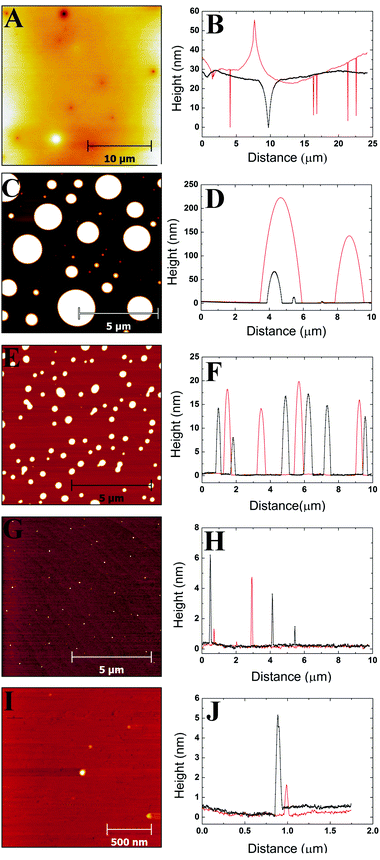 |
| | Fig. 1 A series of AFM height images and profile plots for the 46 kg mol−1 sample at varying concentrations on a mica surface. The profile plots correspond to horizontal line scans taken from the AFM image. (A) 3c* = 17.43 mg ml−1, (B) profile plot at 3c*, (C) 1c* = 5.81 mg ml−1, (D) profile plot at 1c*, (E) 0.1c* = 0.581 mg ml−1, (F) profile plot at 0.1c*, (G) 0.01c* = 0.0581 mg ml−1, (H) profile plot at 0.01c*, (I) 0.001c* = 0.0058 mg ml−1, (J) profile plot at 0.001c*. | |
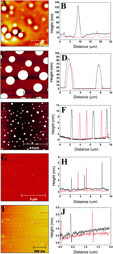 |
| | Fig. 2 A series of AFM height images and profile plots for the 86 kg mol−1 sample at varying concentrations on a mica surface. The profile plots correspond to horizontal line scans taken from the AFM image. (A) 3c* = 11.13 mg ml−1, (B) profile plot at 3c*, (C) 1c* = 3.71 mg ml−1, (D) profile plot at 1c*, (E) 0.1c* = 0.371 mg ml−1, (F) profile plot at 0.1c*, (G) 0.01c* = 0.0371 mg ml−1, (H) profile plot at 0.01c*, (I) 0.001c* = 0.0037 mg ml−1, (J) profile plot at 0.001c*. | |
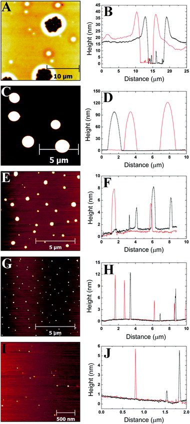 |
| | Fig. 3 A series of AFM height images and profile plots for the 355 kg mol−1 sample at varying concentrations on a mica surface. The profile plots correspond to horizontal line scans taken from the AFM image. (A) 3c* = 4.17 mg ml−1, (B) profile plot at 3c*, (C) 1c* = 1.39 mg ml−1, (D) profile plot at 1c*, (E) 0.1c* = 0.139 mg ml−1, (F) profile plot at 0.1c*, (G) 0.01c* = 0.0139 mg ml−1, (H) profile plot at 0.01c*, (I) 0.001c* = 0.0014 mg ml−1, (J) profile plot at 0.001c*. | |
2.3 Atomic force microscopy (AFM)
All AFM images were obtained using a Bruker Multimode/Nanoscope IIIa (Bruker, Santa Barbara, Ca, USA) in air at room temperature using a J-scanner or E-scanner with an x–y range of ∼160 μm and ∼15 μm respectively. All imaging was carried out in tapping mode using Bruker RTESPA cantilevers with a nominal resonant frequency of 300 kHz, a nominal spring constant of 40 N m−1, and a nominal tip radius of 8 nm. The amplitude set point was kept at approximately 0.6 for all of the imaging. The scans varied in size depending on the sample from 2 μm2 to 150 μm2. The scans were carried out at a frequency of approximately 0.25 Hz. All analysis of the AFM images was carried out using Gwyddion (http://gwyddion.net/) freeware.41
2.4 Deconvolution
Convolution is the apparent increase in the width of objects when imaged using AFM. It is unavoidable and is caused by the finite size of the cantilever tip.42 The convolution effect causes the analysis of the polymer aggregates to be inaccurate as the width of the aggregates appears to be larger than in reality. This also impacts measurements that require a known width such as volume, the number of chains per aggregate, and contact angle. Deconvolution must be implemented in order to obtain a more accurate estimate of the actual lateral size of the polymer aggregates imaged by AFM. On a mica surface, the polymers form spherical cap shaped aggregates from which a ‘real’ volume can be determined using a method developed by Glynos et al.43 where Vr is the real volume of the aggregate after deconvolution, Va is the apparent volume of the aggregate, h is the height of the aggregate which is unaffected by convolution, and Rt is the radius of the AFM tip: Once the ‘real’ volume, Vr, is known for the aggregates then this can be substituted into the equation for the volume of a spherical cap and thus, rearranging gives us a value for the ‘real’ contact radius, rr:| |  | (3) |
The number of chains in each aggregate can then be found by calculating the volume of a single chain by its number-average molecular weight Mn, and its density, ρ:| |  | (4) |
where NA is Avogadro's number, and Vc is the volume of a single polymer chain. The density of the poly(styrene-co-butadiene) copolymers is assumed to be equal to their bulk values (∼0.95 g cm−3).39 The total ‘real’ volume, Vr can then be divided by the volume of a single polymer chain to reveal how many chains made up each aggregate.
2.5 Contact angle measurements
Contact angle measurements were carried out on both nanoscopic and macroscopic aggregates. For the nanoscopic aggregates imaged by AFM, the contact angle can be calculated geometrically using the ‘real’ contact radius of the aggregates, rr, and the height of the aggregates, h:| |  | (5) |
This method provides reliable results when the shape of the aggregate is a spherical cap or spherical and the aggregates are small enough not to be affected by gravity which is the case with the nanodroplets in this study.29
Macroscopic droplets were prepared by depositing small pieces of bulk polymer samples onto the mica surface, followed by thermal equilibration of the samples in an oven at 40 °C which resulted in polymer droplets forming on the mica surface. These droplets had radii ranging from approximately 1 to 5 mm, and volumes from 0.2 to 50 mm3. The 46 kg mol−1 samples required 24 h to reach equilibrium, whilst the 86 kg mol−1 samples required seven days. After over eight weeks in the oven, the polymer with a molecular weight of 355 kg mol−1 did not form droplets on the surface; no macroscopic contact angle measurements were possible for this sample. Macroscopic contact angle measurements were carried out using a KRÜSS Drop Shape Analyser DSA30S at ambient temperatures. Measurements were taken after the samples had been left for one week at ambient temperature.
2.6 Rheology
All rheology measurements were carried out on a Thermo Scientific HAAKE MARS Rheometer. Parallel plate geometry was used for each measurement, and the temperature was set at 20 °C.
2.7 Data analysis
In Fig. 5–7 and 9–14; each point on the graphs represents an average value of either height, radius, the number of chains per aggregate, the number of aggregates or contact angle at a given concentration or molecular weight. These average values of aggregate morphology are taken from a large array of individual aggregates. The bars on the plots are not error bars; they represent the overall range of aggregate values by showing the maximum and minimum values for each array. The reason for this is to examine the distributions of aggregate size at each concentration or molecular weight and observe the level of polydispersity in the aggregate dimensions for each of these parameters. Histograms showing the distributions of aggregate morphology are included in the ESI.† Bars representing standard deviation were not appropriate for many of the data points as they did not have a normal distribution. This can be observed in many of the histograms in the ESI.† The error in the z-direction for AFM measurements is in the sub-nanometer scale, which is at the size of the symbols used (or smaller). Furthermore, we have carried out deconvolution which means the error in the x-direction will also be extremely small. We estimate the error in both x and z directions to be less than 1%.
3 Results and discussion
3.1 AFM images and profiles
Images were obtained from five different polymer solution concentrations. Fig. 1–3 show representative images for each molecular weight of the poly(styrene-co-butadiene) samples. Additionally, typical profile plots are presented for each image, whereby each plot is taken as a complete horizontal line across the image. These profile plots provide a greater insight into the surface morphology of the samples.
3.1.1
M
n = 46 kg mol−1.
Fig. 1A and B show that there is a mostly continuous film formed on the surface at 3c*, only broken by several circular holes with depths ranging from 2.4 nm to 26 nm. There are also some aggregates present on the surface with heights ranging from 16 nm to 36 nm. At lower concentrations (1c*–0.001c*), the polymer forms spherical cap shaped aggregates on the mica surface. The sizes of the aggregates can vary dramatically with solution concentration. Fig. 1C and D show that at 1c*, the aggregates are polydisperse with radii and heights of the aggregates ranging from 10 nm to 910 nm, and 5.6 nm to 241 nm, respectively. Fig. 1E and F show that at 0.1c*, the aggregates have a much narrower range of radius and height values than at 1c*, ranging from 14 nm to 361 nm, and 3.9 nm to 21 nm, respectively. Some droplet coalescence is observed which creates longer, thinner aggregates. Fig. 1G and H show that at 0.01c*, the aggregate radii and heights range from 8.4 nm to 78 nm, and 1.5 nm to 11 nm, respectively. Fig. 1I and J show that at 0.001c*, there is very little polymer present on the mica surface. Very small nanodroplets are formed with radii and heights ranging from 5.1 nm to 44 nm, and 2.3 nm to 7.7 nm, respectively. The range of radii and heights is smallest at this concentration.
3.1.2
M
n = 86 kg mol−1.
Fig. 2A and B show the polymer morphology at 3c*, a mostly continuous polymeric film is observed on the surface. However, some dewetting is observed, characterised by the large circular aggregates with holes around them. The depth of these holes ranges from 2.2 nm to 17 nm, and the height of the aggregates ranges from 9.2 nm to 634 nm. Once again spherical cap shaped aggregates are formed at all lower concentrations. Fig. 2C and D show that at 1c* the aggregates have the largest ranges of radii and heights from 16 nm to 1.1 μm, and 2.1 nm to 411 nm, respectively. Fig. 2E and F show that at 0.1c*, the aggregate radii and heights range from 4.7 nm to 383 nm, and 3.4 nm to 46 nm, respectively. Fig. 2G and H show that at 0.01c*, the range of aggregate radii and heights is lower than 1c* and 0.1c* with values from 6.2 nm to 92 nm, and 1.3 nm to 12 nm, respectively. Fig. 2I and J show that at 0.001c*, very small aggregates are observed with radii and heights ranging from 3.7 nm to 35 nm, and 1.4 nm to 6.7 nm, respectively. As for the 46 kg mol−1 sample, the average range of radii and heights of the aggregates is lowest at this concentration.
3.1.3
M
n = 355 kg mol−1.
Fig. 3A and B show that at 3c* a mostly continuous film forms on the surface. More dewetting is observed on the surface and there are a number of large holes with depths ranging from 2.9 nm to 32 nm which exhibit raised outer rims. Aggregates are observed on the film with heights ranging from 8.7 nm to 342 nm. At 3c*, there is a larger degree of dewetting for this sample compared to the two lower molecular weights. Similarly to the previous molecular weights, spherical cap shaped aggregates are observed at all other concentrations. Fig. 3C and D show that at 1c*, aggregate radii and heights range from 95 nm to 1.1 μm, and 26 nm to 211 nm, respectively. Fig. 3E and F show that at 0.1c*, fairly uniform aggregates were formed with a narrower range of radii (16 nm to 324 nm) and heights (2.9 nm to 191 nm) compared to the 1c* sample. Fig. 3G and H show that at 0.01c*, uniform aggregates were formed with radii and heights ranging from 6.8 nm to 72 nm, and 2.2 nm to 29 nm, respectively. Fig. 3I and J show that at 0.001c*, very small aggregates form with aggregate radii and height ranging from 7.9 nm to 63 nm, and 1.1 nm to 10 nm, respectively.
3.1.4 Spherical cap shaped aggregates.
In order to confirm that the nanodroplets are spherical cap shaped, cross-sectional profile plots of individual droplets were fitted to spherical caps. The equation used to fit the spherical cap profile is| |  | (6) |
where Z is the vertical coordinate, Rs is the radius of the sphere, and x is the horizontal coordinate. Fig. 4 shows an example of a typical cross-sectional profile plot of a nanodroplet fitted to a spherical cap. From the results, it is clear that the profiles of the nanodroplets are fitted well with the 2D equation confirming that the droplets themselves are spherical caps.
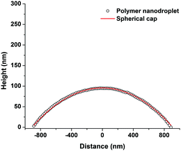 |
| | Fig. 4 A typical cross-sectional profile plot of a poly(styrene-co-butadiene) random copolymer nanodroplet fitted to a spherical cap. | |
3.2 Concentration effects
Plots in Fig. 5–7 show the average values and the range of values for aggregate radius, height, and the number of chains per aggregate against concentration across the three molecular weights on the mica surface.
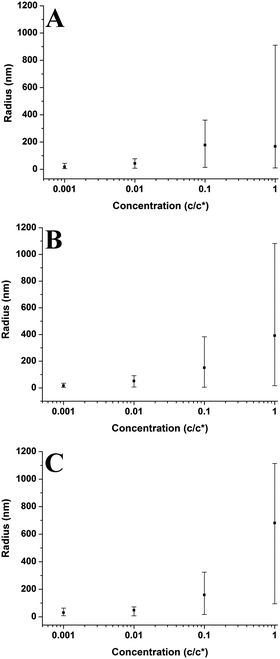 |
| | Fig. 5 Graphs showing how concentration affects the radius of the polymer aggregates on the mica surface at varying molecular weights. Each graph presents the average values and has bars which indicate the range of values. (A) Mn = 46 kg mol−1, (B) Mn = 86 kg mol−1, (C) Mn = 355 kg mol−1. | |
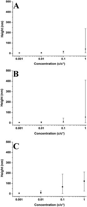 |
| | Fig. 6 Graphs showing how concentration affects the height of the polymer aggregates on the mica surface at varying molecular weights. Each graph presents the average values and has bars which indicate the range of values. (A) Mn = 46 kg mol−1, (B) Mn = 86 kg mol−1, (C) Mn = 355 kg mol−1. | |
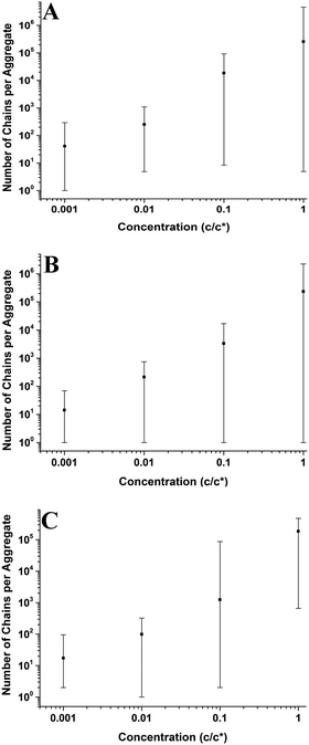 |
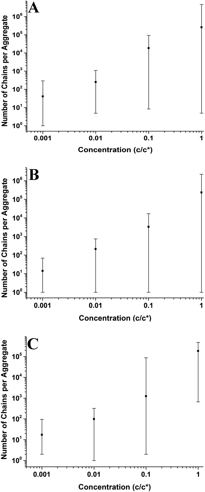
| | Fig. 7 Graphs showing how concentration affects the number of chains per aggregate on the mica surface at varying molecular weights. Each graph presents the average values and has bars which indicate the range of values. (A) Mn = 46 kg mol−1, (B) Mn = 86 kg mol−1, (C) Mn = 355 kg mol−1. | |
3.2.1 Size distribution of aggregates.
Fig. 5 shows how the radius of the aggregates varies with concentration at different molecular weights. The aggregate radius increases non-linearly with increasing concentration; the range of aggregate radii is largest at 1c* and it decreases with decreasing concentration across all molecular weights. The aggregates formed at 1c* are polydisperse but at the lowest concentrations, the aggregates are more monodisperse with consistently small radii. The radius of the aggregates can vary considerably in size, but their spherical cap shape is independent of individual aggregate size. Polymers on non-wetting surfaces in a poor solvent (in our case air) form aggregates of a spherical cap shape to minimize free energy.44
Fig. 6 shows that the height of the aggregates increases with increasing concentration on the mica surface for each of the three molecular weights. This trend is similar to the relationship between aggregate radius and concentration, as the overall height and the range of heights are largest at higher concentrations. At higher concentrations, there are many polymer chains present at the surface during the solvent evaporation and drying processes. This allows (via entanglements) the creation of some aggregates with larger sizes upon drying (as the solvent conditions change due to the evaporation of the solvent). Conversely, at lower concentrations, there are simply not enough chains at the surface for large aggregates to form upon drying, leading to a much smaller range of aggregate sizes.
3.2.2 Number of chains per aggregate and single chain nanodroplets.
Fig. 7 shows that the number of chains per aggregate increases with concentration; at higher concentrations, the aggregate size is larger and therefore the individual aggregates will be made up of more polymer chains. Similarly, with aggregate radius and height, the range of the number of chains per aggregate is much larger at higher concentrations. There are still many smaller aggregates present on the surface, even down to single chains. At the lowest concentration (0.001c*), the average number of chains per aggregate is consistently low (14–41) showing that aggregates form that contain very few polymer chains. Although single chains were observed most frequently at 0.001c*, some single chains were present at higher concentrations as well. For the 46 kg mol−1 sample in Fig. 7A, the average height of the single chains was 2.5 nm and the average radius was 4.4 nm; for the 86 kg mol−1 sample in Fig. 7B, the average height and radius of the chains was 3.3 nm and 5.2 nm, respectively; and for the 355 kg mol−1 sample shown in Fig. 7C, the average height of the chains was 3.1 nm and the average radius was 6.5 nm. As a polymer chain adsorbed flat on a surface has a characteristic height and a width of ∼0.4 nm,45,46 these results show that single chains on mica do not lie flat at the interface. A single hydrophobic polymer chain will instead create a globule, folding to dewet the hydrophilic mica surface and create a nanodroplet. This behaviour is very similar to the behaviour of the larger aggregates.
3.2.3 Thin film morphology.
At 3c*, across all molecular weights, the polymers form mostly continuous films on the mica surface and not spherical cap shaped aggregates. Often polymer thin films are not homogenous and flat, but unstable. For instance, when polystyrene ultrathin films (<100 nm) are annealed above their Tg, they become unstable and dewetting can occur.47,48 While stability and smoothness are maintained below the Tg in the spin-cast films. As the poly(styrene-co-butadiene)s used in this study exhibit very low Tg values, the thin films should be unstable at room temperature. This dewetting phenomenon can generally be separated into three stages. First, many small cylindrical holes are formed in the film, this is often thought to occur due to unstable rapid nucleation caused by small imperfections and impurities on the substrate (or the film itself) or to spinodal dewetting caused by thermal fluctuations.49–51 This is exemplified in Fig. 1A which shows a mostly continuous film with some small cylindrical holes which is typical of the early stages of dewetting. The second stage of dewetting is characterised by larger holes that have asymmetrical raised rims. This is observed in Fig. 3A with both large holes and viscous fingering patterns present in the film. It is thought that after nucleation, capillary forces drive the dewetting process and force the polymer chains to accumulate around the circumference of the hole to form a raised rim.52 We have observed that the heights of the raised rims increase linearly with the diameter of the dewetted holes. Fig. 8 shows this relationship for the holes formed at 3c* for the 355 kg mol−1 sample. The same trend has previously been observed by G. Reiter when studying the dewetting phenomena of almost glassy polystyrene thin films close to their Tg.52 Reiter claimed that this relationship meant the polymer was not flowing like a liquid, and capillary forces were plastically deforming the highly elastic polymer films. This is an interesting result, as we have demonstrated that this linear relationship between the rim height and the hole diameter is also true for our viscous polymers which at room temperature should be well above their Tg. In contrast to Reiter, we also observed viscous finger patterns in our samples; these occur when frictional forces acting at the interface between the polymer and the substrate oppose the hole growth which induces rim instability. This rim instability leads to the formation of viscous fingering patterns, which are characteristic of polymer films above their Tg.53 For our poly(styrene-co-butadiene) thin films, we observe viscous fingering patterns in the holes, as well as, a linear relationship between the rim height and the hole diameter. This suggests that our polymers do not behave as a simple fluid but exhibit aspects of both viscous and plastic behaviour. The final stage of dewetting is when the holes are large enough to coalesce, with Plateau–Rayleigh instability causing droplets to form on the surface. The droplets on the surface have reached equilibrium and this signifies the end of the dewetting process.49
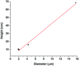 |
| | Fig. 8 Graph showing the linear relationship between rim height and hole diameter for dewetted holes. The measurements were carried out on 9 holes in the polymer films formed at 3c* for the 355 kg mol−1 sample. | |
Many factors can affect this dewetting behaviour including molecular weight, solvent evaporation, film thickness, annealing time, and chemical composition.50 A very common study of dewetting is carried out with polystyrene films on silicon substrates, which involves annealing films above the Tg to promote dewetting.52,54,55 The samples are then quenched back to room temperature to “freeze” the polymer surface and lock the dewetting structures in place. For these polystyrene films, the amount of dewetting increases with annealing time until droplets are formed on the silicon and the system reaches equilibrium; more annealing has no effect. Several hours of annealing at temperatures generally ranging from 5 °C to 50 °C above the Tg values of polystyrene are required to form droplets. Interestingly, different results are observed with poly(styrene-co-butadiene) on mica. Despite the polymers in our study being approximately 55 °C above their Tg's throughout the experiments (16–72 hours), equilibrium structures are not formed at 3c* where total dewetting would be expected. Dewetting occurs very slowly in this system, potentially due to a change in the polymer's Tg in the vicinity of a surface, as interfaces and confinement can impact these temperatures.7,56 Importantly, we show that the poly(styrene-co-butadiene) thin films on mica appear to be in metastable equilibrium and dewet the mica surface very slowly.
To further investigate the dewetting mechanisms of the polymer on the mica surface, AFM imaging was carried out 15 minutes after the spin coating process. This meant that the early stages of dewetting could be examined and compared to the polymer formation after 16–72 hours of drying. Typical AFM images comparing the polymer formation of the 46 kg mol−1 sample after approximately 15 minutes of drying and 16–72 hours of drying at room temperature can be found in the ESI.† For the 46 kg mol−1 sample at a concentration of 1c*, a mostly continuous thin film was observed on the mica surface after 15 minutes of drying. The film had many small holes, as well as, some circular aggregates. The holes reached depths of up to 3.3 nm. In contrast, when the 1c* sample is left for 16–72 hours, we observed spherical cap shaped aggregates on the surface. This shows that at the overlap concentration, dewetting does not occur immediately after polymer deposition during the solvent evaporation or initial drying processes. Instead, most of the dewetting occurs during the 16–72 hours the samples are left to completely dry in the fume hood. At a concentration of 0.1c*, we observed similar results after both 15 minutes of drying and 16–72 hours of drying whereby spherical cap shaped nanodroplets formed on the mica surface. This shows that at lower concentrations, the majority of dewetting occurs very soon after polymer deposition during solvent evaporation or initial drying. Interestingly, the average radii and heights of the polymer droplets after 15 minutes drying are 14% and 36% larger than the nanodroplets that have been dried for 16–72 hours. This is likely because after 15 minutes, the polymer aggregates are not completely dry and therefore the chains will be swollen slightly creating larger droplets. These results show that the time it takes for dewetting to occur is influenced by solution concentration. At lower concentrations, dewetting occurs quickly, whilst at higher concentrations, this occurs over a larger time scale such that when the concentration is increased up to 3c*, only partial dewetting is observed and the thin films enter a state of metastable equilibrium.
3.3 Molecular weight effects
3.3.1 Size distribution of aggregates.
Fig. 9–11 show the relationship between molecular weight and aggregate radius, height, and number of chains per aggregate at varying concentrations. Fig. 9 shows that at a concentration of 1c* and 0.001c*, the overall radius of the aggregates increases with increasing molecular weight. However, for other concentrations, the radius remains nearly constant with increasing molecular weight. The range of radius values is large and similar across the molecular weight range.
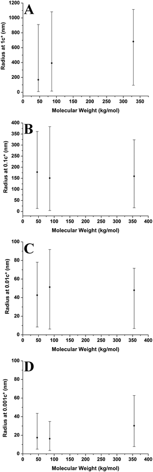 |
| | Fig. 9 Graphs showing how molecular weight affects the radius of the polymer aggregates on the mica surface at varying concentrations. Each graph presents the average values and has bars which indicate the range of values. (A) 1c*, (B) 0.1c*, (C) 0.01c*, (D) 0.001c*. | |
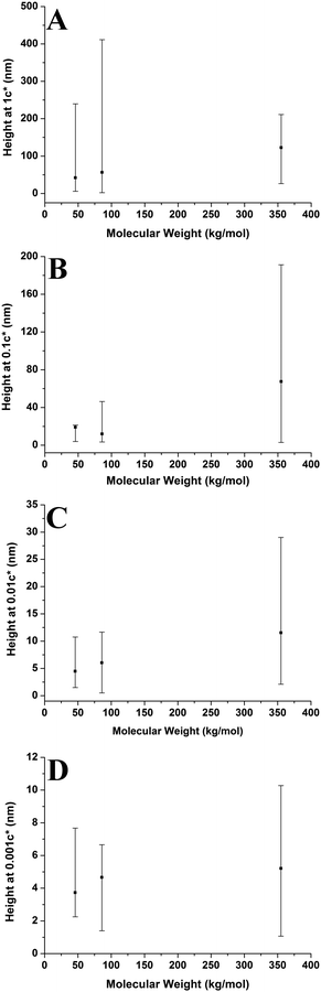 |
| | Fig. 10 Graphs showing how molecular weight affects the height of the polymer aggregates on the mica surface at varying concentrations. Each graph presents the average values and has bars which indicate the range of values. (A) 1c*, (B) 0.1c*, (C) 0.01c*, (D) 0.001c*. | |
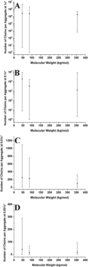 |
| | Fig. 11 Graphs showing how molecular weight affects the number of chains per aggregate on the mica surface at varying concentrations. Each graph presents the average values and has bars which indicate the range of values. (A) 1c*, (B) 0.1c*, (C) 0.01c*, (D) 0.001c*. | |
Fig. 10 shows aggregate height against molecular weight at varying concentrations. The overall height of the aggregates increases with increasing molecular weight; however this is not a strong trend at 0.001c*. The range of heights is generally largest for the higher molecular weight sample, with the lower molecular weight samples having smaller ranges. However, this is not the case at 1c* where the higher molecular weight sample has the smallest range of values. The results show that generally the aggregate height increases with increasing molecular weight; both higher solution viscosities and greater degrees of entanglement at higher molecular weights may play a role in shaping this behaviour (vide infra).
Fig. 11 shows the number of chains per aggregate against molecular weight at varying concentrations. As the molecular weight increases, the number of chains per aggregate decreases, although there is only a weak trend for the 1c* and 0.1c* samples. While the height of the aggregates increases with molecular weight, the individual polymer chains are longer at higher molecular weights, requiring fewer chains to make a larger aggregate. For the 46 kg mol−1 sample, the range of number of chains per aggregates is observed to be largest at the two lower concentrations and also fairly large at the two higher concentrations. This is because there are a greater number of shorter chains in the solution, which induces a larger range of chains per aggregate.
Fig. 9–11 also demonstrate that aggregates are generally larger in size at higher molecular weights, which is also correlated with the average film thickness at 3c* (6.6 nm, 8.4 nm, and 19 nm for 46 kg mol−1, 86 kg mol−1, and 355 kg mol−1 samples, respectively). The film thicknesses were measured by taking cross-sectional profile plots across the holes in the AFM images at 3c*. A detailed outline of this process and an example of a typical profile plot are included in the ESI.† This increase in aggregate size and film thickness at higher molecular weights is likely influenced by the viscosity of a sample, which will generally increase with increasing molecular weight.57 If the viscosity is increased, there may be fewer polymeric materials expelled from the surface during spin coating, leaving behind larger aggregates and thicker films. Remember that the polymer solutions in this study have been prepared relative to the individual polymer's overlap concentration. This means that as the molecular weight of the polymer is increased, the total mass of the polymer in solution is decreased. As the concentration by weight of a polymer solution decreases then so will the viscosity.58 These two factors thus work in opposite ways. To further investigate this, rheology measurements were carried out at 1c* to determine the viscosity of solutions containing polymers of each molecular weight. The measured dynamic viscosity of toluene at 20 °C was 0.59 mPa s, which is consistent with previous reports,59 while the dynamic viscosities of the 1c* polymer solutions were 0.80, 0.81, and 0.85 mPa s for the 46, 86, and 355 kg mol−1 samples respectively. The relative viscosities are therefore 1.36, 1.37, and 1.44 for the three samples. This confirms that the viscosity of the solutions does increase with increasing molecular weight under these conditions. As the sample viscosity increases, larger aggregates and thicker films form, providing a significant reason for the change in aggregate size with molecular weight.
The change in viscosity is not the only factor that creates larger aggregates at higher molecular weights as chain entanglements are also significant. Fig. 12 shows the average number of aggregates in a specific area of the mica surface against molecular weight at varying concentrations. As the molecular weight increases the number of aggregates present on the surface generally decreases and the range of values is mostly lowest at 355 kg mol−1. However, the number of aggregates remains constant at a concentration of 0.01c*. We have established that as the molecular weight increased, there are fewer but larger polymer aggregates present on the mica surface. As the solutions are prepared according to the overlap concentration, polymers with larger molecular weights will have fewer but larger chains present in the solution. The polymer chains will be in the same proximity to each other in a solution at a given concentration, regardless of molecular weight. Polymer chains with higher molecular weights will experience more entanglements than chains with lower molecular weights. Therefore, at higher molecular weights, the smaller quantity of larger chains will entangle to a greater degree compared to the lower molecular weight chains; hence creating fewer but larger aggregates on the mica surface. Consequently, increased chain entanglements are also responsible for the changes in the polymer morphology on the mica surface.
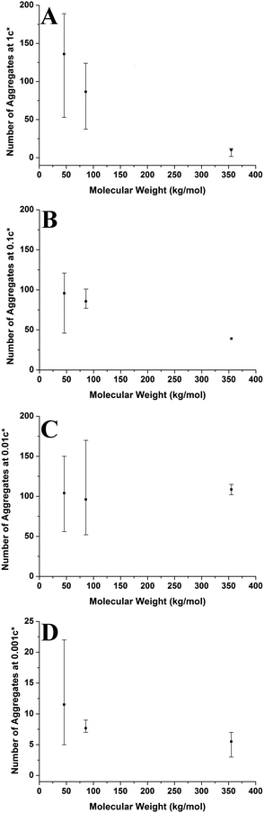 |
| | Fig. 12 Graphs showing how molecular weight affects the number of polymer aggregates on a specific surface area of mica at varying concentrations. Each graph presents the average values and has bars which indicate the range of values. (A) 1c*, (B) 0.1c*, (C) 0.01c* (D) 0.001c*. | |
3.3.2 Film morphology.
Finally, at 3c*, higher molecular weights correlate with increased dewetting, best observed by comparing Fig. 1A, 2A and 3A. It has also been reported that the dewetting phenomena of polymer films can be highly dependent on film thickness. This is because, factors that affect dewetting such as the magnitude of the van der Waals force acting on the film are heavily influenced by film thickness.49 When films are thicker, dewetting will take place at a faster rate and larger holes with raised rims and Hele-Shaw patterns are often observed. Also, it is reported that for films with a low thickness, there will be a greater number of holes in the film but less dewetting overall.52 In polystyrene samples, increasing the molecular weight will increase the thickness of the thin film spin coated on a surface at a fixed concentration.57 This agrees with our results; increasing the molecular weight of the polymers results in greater thickness of the thin films, and therefore more dewetting is observed. Regardless of the molecular weight, the polymer films formed at 3c* always experience some degree of dewetting and total wetting is never observed. This is likely due to very low Tg values of the polymers which means under ambient conditions, a distinct wetting/dewetting transition line is not observed.60
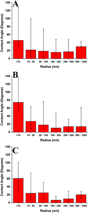
3.4 Contact angle effects
Fig. 13 compares the average contact angle and the range of contact angle values of the polymer droplets against concentration at varying molecular weights on the mica surface. Generally, it is observed that at 1c* and 0.001c*, the average contact angle of the droplets is largest, and the minimum values are at 0.01c* or 0.1c*. The range of values is largest at 1c* for the lower molecular weight samples; however, for the highest molecular weight samples the range of values is largest at 0.001c*. These results suggest that the contact angles of the droplets are size dependent and that the contact angle appears to be larger for both the very small droplets and much larger droplets. However, as explained previously there are many small droplets present at higher concentrations which could affect this conclusion. Fig. 14 shows the average contact angle and the range of contact angle values against the nanodroplet radius across varying concentrations at each molecular weight. These plots correct the previous ambiguity and confirm that there is a systematic droplet size dependence on the contact angle. The overall trend is independent of the molecular weight; the contact angle values are largest for both the smaller and bigger droplets, and a minimum is present at 100–250 nm. Cross-sectional profile plots of nanodroplets with radii ranging from 100–250 nm were fitted well to spherical caps; this confirmed that despite their low contact angles, the nanodroplets in this size range maintained a spherical cap shape. Examples of these cross-sectional profile plots fitted to spherical caps are included in the ESI.† When a droplet radius is smaller than 100–250 nm, a sharp increase in contact angle is observed. The contact angle is at a maximum when the droplet radius is <10 nm across each molecular weight. At this range of radii, the droplets are made up of single chains or aggregates containing very few chains and the average contact angles are 46°, 75°, and 61° for the 46 kg mol−1, 86 kg mol−1, and 355 kg mol−1 samples, respectively. These contact angle values are large and indicate that single polymer chains or very small aggregates will not lie flat on the mica, but will strongly dewet the surface. Evangelopoulos et al.34 observed that as the size of polybutadiene droplets was reduced to the nanoscale on a mica surface, the dewetting of the nanodroplets increased. They showed that surface and line tension effects cannot explain the observed behaviour and attributed it to an increased elastic modulus. After a certain critical value of size (at the nanoscale), the elastic modulus of the polymer droplets began to exponentially increase which increased dewetting and thus the contact angle. This is due to the effect of confinement which occurs when a polymer is in the proximity of a surface, and can have an entropic origin.61–65 This phenomenon has also been reported with polymer nanofibers.35,66,67 The materials and methods used in the study of Evangelopoulos et al.34 are similar to the ones used in our experiments, and their results agree with our observations. However, a simulation study carried out by Milchev et al.68 also showed very similar results to our own, but instead attributed this behaviour to line tension. They found that when a polymer droplet was subjected to long-range van der Waals forces on a flat substrate with weak polymer/substrate adhesion, there was a distinct size dependence on the contact angle of the nanodroplets. The droplets underwent a sharp increase in contact angle as the droplet size was reduced in the nanoscale, and this was attributed to the existence of a positive line tension influencing droplet morphology. These results also agree with our own observations as we have weak adhesion between our polymer nanodroplets and the mica surface. However, the study of line tension is a controversial subject and neither the magnitude nor the sign of the line tension value is currently established.31,32 For example, Seeman et al.33 calculated the line tension of polystyrene nanodroplets on a silicon dioxide substrate to have a negative value. These opposite results regarding line tension at the nanoscale are not uncommon. However in this case, they could possibly be attributed to the differences in polymer/substrate adhesion. We have presented two studies with results that agree with our own experimental data regarding the size dependence on the contact angle of polymer nanodroplets. Currently, whilst we cannot decisively confirm either theory with our quantitative results, it appears that both are plausible. It is worthwhile noting that it is possible that for polymer nanodroplets on surfaces, positive line tension and an increased elastic modulus may be intrinsically linked creating the observed changes in the nanodroplet contact angle.
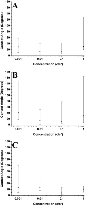 |
| | Fig. 13 Graphs showing how concentration affects the contact angle of polymer aggregates on the mica surface at varying molecular weights. Each graph presents the average values and has bars which indicate the range of values. (A) Mn = 46 kg mol−1, (B) Mn = 86 kg mol−1, (C) Mn = 355 kg mol−1. | |
 |
| | Fig. 14 Graphs showing the radius against contact angle for the nanodroplets on a mica surface at varying molecular weights. Each graph presents the average values and has bars which indicate the range of values. (A) Mn = 46 kg mol−1, (B) Mn = 86 kg mol−1, (C) Mn = 355 kg mol−1. | |
Furthermore, Fig. 14 shows that when the droplet radii are larger than 100–250 nm the contact angle of the polymer droplets also increases. Fig. 15 shows the relationship between the contact angle and the radius for the poly(styrene-co-butadiene) random copolymer droplets with molecular weights of 46 kg mol−1 and 86 kg mol−1 at the macroscale. An annotated photograph showing a typical macroscopic polymer droplet on the mica surface is included in the ESI.† The macroscopic angles are larger than the minimum in Fig. 13, with values ranging from 30° to 36° for the 46 kg mol−1 sample, and values ranging from 34° to 41° for the 86 kg mol−1 sample. However, unlike the nanoscale, there is no apparent droplet size dependence on the contact angle. The contact angle of the droplets appears to be fairly independent of the droplet radius at the macroscale. The combination of nanoscopic and macroscopic measurements shows that when the radius of the droplets is larger than 100–250 nm, the contact angle increases with the droplet radius until it reaches the plateau of the macroscopic contact angle values. Checco et al.30 observed that the contact angle of alkane droplets increased with increasing droplet radius from approximately 200 nm to macroscopic levels. They concluded that line tension could not explain this behaviour and instead cited surface heterogeneities as the cause; the droplets will form on the most wettable parts of the surface; the existence of surface heterogeneities make this more probable for smaller droplets. On the contrary, larger droplets will not be able to avoid heterogeneities and thus will have larger contact angles; the same can apply for our system. Freshly cleaved mica is hydrophilic but becomes less hydrophilic rather rapidly creating surface heterogeneities.69 The size of heterogeneities are in the sub-micrometer range,46 fitting with the minimum of the contact angle in the region of 100–250 nm that we have measured.
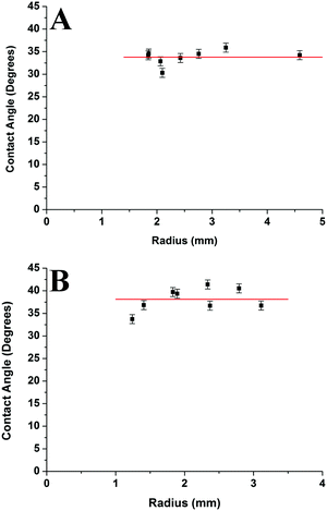 |
| | Fig. 15 Graphs showing the droplet radius against contact angle for macroscopic poly(styrene-co-butadiene) droplets at varying molecular weights on a mica surface. Measurements were taken 1 week after the samples were removed from the oven. Each horizontal line represents the overall average value of the measurements. The bars on the graphs represent the experimental error. (A) Mn = 46 kg mol−1, (B) Mn = 86 kg mol−1. | |
Thus, we have found a distinct range of droplet radii where the polymer droplet's contact angle is at a minimum for every molecular weight indicating that this is a substrate surface effect. As the droplet size is increased the contact angle increases until it plateaus to its macroscopic value. As the polymer droplet's radius is decreased from the minimum, a sharp increase in contact angle is observed owing to the increase of the elastic modulus. To our knowledge, this is the first observation of such a contact angle behaviour and may prove to be useful in controlling the wetting properties of polymer droplets from the nanoscale to the macroscale.
4 Conclusions
Varying solution concentration and molecular weight have a significant impact on polymer morphology on a mica surface. At the highest concentration we examined, mostly continuous thin films formed on the mica surface with the higher molecular weight samples having a greater thickness. Only partial dewetting is observed in the films despite the low Tg of the polymers, which means that the polymers are in a state of metastable equilibrium. Additionally, we show that the polymers do not behave like a simple fluid but exhibit both viscous and plastic behaviour. This is demonstrated by the observation of both a linear relationship between the rim height and the hole diameter of the dewetted holes, which is characteristic of plastic behaviour, as well as, fingering patterns which are characteristic of viscous behaviour. We have provided an insight into the relatively unexplored field of thin films composed of polymers with Tg's well below room temperature. Studying their dewetting mechanisms, we have shown that the polymer films are in metastable equilibrium and cannot be treated as a simple system.
At the overlap concentration nanodroplets form over a larger time scale (16–72 hours at room temperature) due to more polymeric material being present on the surface. At lower concentrations, total dewetting occurs over a small time scale and spherical cap shaped nanodroplets form on the mica surface during the solvent evaporation and spin coating processes. The size of the nanodroplets varies from single chains to aggregates containing millions of chains. Single polymer chains dewet the mica surface and form spherical cap shaped nanodroplets. At higher concentrations, the average size of the aggregates was larger, although the nanodroplet distributions were polydisperse. At lower concentrations, the aggregates were much smaller on average, but their size distributions were more monodisperse. Changing the molecular weight also affects the formation of the spherical cap shaped nanodroplets; as the molecular weight is increased, there are fewer but larger aggregates present on the surface. This is due to more polymer entanglements and an increase in solution viscosity that occurs at these higher molecular weights. We have demonstrated that altering molecular weight and solution concentrations of the polymer samples does not only affect the size of the nanodroplets formed on the mica surface. There is also a significant impact on the number of droplets present on a surface and the size distributions of the nanodroplets. This result provides further insight into polymer behaviour at an interface and suggests how the morphology of polymer aggregates could be controlled by altering basic parameters.
We have also shown that there is a specific size dependence on the contact angle of the droplets at the nanoscale. A distinct minimum in the contact angle was observed for droplets with radii ranging from 100–250 nm across each molecular weight. When the droplet size is lower than this minimum, a sharp increase in contact angle was observed. This appears to be due to an exponential increase in the elastic modulus that occurs below a critical value in the nano-regime (<100 nm) or a positive line tension value due to weak polymer/substrate adhesion. For larger droplet sizes, an increase in contact angle was observed which plateaus at the macroscale. We attribute this effect to surface heterogeneities causing preferential wetting. Our results show that the contact angle behaviour in the nanoscale is the result of two opposing factors: the elastic modulus increase/line tension at <100 nm and the existence of heterogeneities at the substrate surface, which affects aggregates with radii larger than 250 nm. This systematic trend is previously unexplored and may prove valuable in understanding and controlling the wetting properties of polymer nanodroplets at an interface. We have shown a distinct difference in the contact angle behaviour of polymer droplets at the nanoscale compared to the micro and macroscale, which is of fundamental significance and relevant to applications, such as miniaturisation of devices and sensors.
Competing financial interest
The authors declare no competing financial interest.
Acknowledgements
We thank Michelin and Marc Couty for providing the polymer samples and carrying out GPC and DSC measurements. We acknowledge the EPSRC and the SOFI CDT (Grant Ref. No. EP/L015536/1) for the financial support.
References
-
A. Y. Grosberg and A. R. Khokhlov, Giant Molecules, Academic Press, San Diego, 1997, pp. 1–5 Search PubMed.
- M. A. C. Stuart, W. T. S. Huck, J. Genzer, M. Müller, C. Ober, M. Stamm, G. B. Sukhorukov, I. Szleifer, V. V Tsukruk, M. Urban, F. Winnik, S. Zauscher, I. Luzinov and S. Minko, Nat. Mater., 2010, 9, 101–113 CrossRef PubMed.
- D. J. C. Herr, J. Mater. Res., 2011, 26, 122–139 CrossRef CAS.
- S. Kienle, M. Gallei, H. Yu, B. Z. Zhang, S. Krysiak, B. N. Balzer, M. Rehahn, A. D. Schluter and T. Hugel, Langmuir, 2014, 30, 4351–4357 CrossRef CAS PubMed.
- S. Stankovich, D. A. Dikin, G. H. B. Dommett, K. M. Kohlhaas, E. J. Zimney, E. A. Stach, R. D. Piner, S. T. Nguyen and R. S. Ruoff, Nature, 2006, 442, 282–286 CrossRef CAS PubMed.
- Y. Li, K. Hu, X. Han, Q. Yang, Y. Xiong, Y. Bai, X. Guo, Y. Cui, C. Yuan, H. Ge and Y. Chen, Langmuir, 2016, 32, 3670–3678 CrossRef CAS PubMed.
- H. Mortazavian, C. J. Fennell and F. D. Blum, Macromolecules, 2016, 49, 4211–4219 CrossRef CAS.
- M. Maddumaarachchi and F. D. Blum, J. Polym. Sci., Part B: Polym. Phys., 2014, 52, 727–736 CrossRef CAS.
- J. Kumaki, Polym. J., 2016, 48, 3–14 CrossRef CAS.
- M. Kalloudis, E. Glynos, S. Pispas, J. Walker and V. Koutsos, Langmuir, 2013, 29, 2339–2349 CrossRef CAS PubMed.
- J. Zhao, S. Tian, Q. Wang, X. Liu, S. Jiang, X. Ji, L. An and B. Jiang, Eur. Phys. J. E: Soft Matter Biol. Phys., 2005, 16, 49–56 CrossRef CAS PubMed.
- A. S. Sarac, S. A. M. Tofail, M. Serantoni, J. Henry, V. J. Cunnane and J. B. McMonagle, Appl. Surf. Sci., 2004, 222, 148–165 CrossRef CAS.
- S. H. Baxamusa and K. K. Gleason, Adv. Funct. Mater., 2009, 19, 3489–3496 CrossRef CAS.
-
J. Rose, M. Auffan, O. Proux, V. Niviere and J. Y. Bottero, in Encyclopedia of Nanotechnology, ed. B. Bhushan, Springer, The Netherlands, 2012, pp. 84–104 Search PubMed.
- R. N. Jagtap and A. H. Ambre, Indian J. Eng. Mater. Sci., 2006, 13, 368–384 CAS.
- T. Anzai, M. Kawauchi, T. Kawauchi and J. Kumaki, J. Phys. Chem. B, 2015, 119, 338–347 CrossRef CAS PubMed.
- J. Kumaki, T. Kawauchi and E. Yashima, Macromolecules, 2006, 39, 1209–1215 CrossRef CAS.
- K. Sugihara and J. Kumaki, J. Phys. Chem. B, 2012, 116, 6561–6568 CrossRef CAS PubMed.
- J. Kumaki and T. Hashimoto, J. Am. Chem. Soc., 2003, 125, 4907–4917 CrossRef CAS PubMed.
- J. Kumaki, Y. Nishikawa and T. Hashimoto, J. Am. Chem. Soc., 1996, 118, 3321–3322 CrossRef CAS.
- T. R. Albrecht, M. M. Dovek, C. A. Lang, P. Grütter, C. F. Quate, S. W. J. Kuan, C. W. Frank and R. F. W. Pease, J. Appl. Phys., 1988, 64, 1178–1184 CrossRef CAS.
- M. Ouchi, N. Badi, J.-F. J. Lutz and M. Sawamoto, Nat. Chem., 2011, 3, 917–924 CrossRef CAS PubMed.
- V. Koutsos, E. W. van der Vegte, E. Pelletier, A. Stamouli and G. Hadziioannou, Macromolecules, 1997, 30, 4719–4726 CrossRef CAS.
- V. Koutsos, E. W. van der Vegte and G. Hadziioannou, Macromolecules, 1999, 32, 1233–1236 CrossRef CAS.
- J. Junhyeok, K. Masayuki and Y. Hirohisa, J. Therm. Anal. Calorim., 2012, 39, 33–37 Search PubMed.
- G. Sato, S. Nishitsuji and J. Kumaki, J. Phys. Chem. B, 2013, 117, 9067–9072 CrossRef CAS PubMed.
- G. Tracz, A. Jeszka, J. Kucińska, I. Chapel and J. Boiteux, Macromol. Symp., 2001, 169, 129–135 CrossRef.
- V. V. Prokhorov and K. Nitta, J. Polym. Sci., Part B: Polym. Phys., 2010, 48, 766–777 CrossRef CAS.
-
Y. Yuan and T. R. Lee, in Surface Science Techniques, Springer Series in Surface Sciences, 51, ed. G. Bracco and B. Holst, Berlin, 2013, pp. 3–34 Search PubMed.
- A. Checco, P. Guenoun and J. Daillant, Phys. Rev. Lett., 2003, 91, 186101 CrossRef PubMed.
- D. Li, Colloids Surf., A, 1996, 116, 1–23 CrossRef CAS.
- H. Peng, G. R. Birkett and A. V. Nguyen, Mol. Simul., 2014, 40, 934–941 CrossRef CAS.
- R. Seemann, K. Jacobs and R. Blossey, J. Phys.: Condens. Matter, 2001, 13, 4915–4923 CrossRef CAS.
- A. E. A. S. Evangelopoulos, E. Glynos, F. Madani-Grasset and V. Koutsos, Langmuir, 2012, 28, 4754–4767 CrossRef CAS PubMed.
- A. Arinstein, M. Burman, O. Gendelman and E. Zussman, Nat. Nanotechnol., 2007, 2, 59–62 CrossRef CAS PubMed.
-
V. J. Morris, A. R. Kirby and A. P. Gunning, Atomic Force Microscopy for Biologists, Imperial College Press, London, 2009, pp. 56–57 Search PubMed.
- L. J. Fetters, D. J. Lohse, S. T. Milner and W. W. Graessley, Macromolecules, 1999, 32, 6847–6851 CrossRef CAS.
- L. J. Fetters, D. J. Lohse and W. W. Graessley, J. Polym. Sci., Part B: Polym. Phys., 1999, 37, 1023–1033 CrossRef CAS.
-
M. Rubinstein and R. H. Colby, Polymer Physics, Oxford University Press, Oxford, 2003, pp. 1–55 Search PubMed.
- Q. Ying and B. Chu, Macromolecules, 1987, 20, 362–366 CrossRef CAS.
- D. Nečas and P. Klapetek, Open Phys., 2012, 10, 181–188 Search PubMed.
- P. Markiewicz and M. C. Goh, Langmuir, 1994, 10, 5–7 CrossRef CAS.
- E. Glynos, A. Chremos, G. Petekidis, P. J. Camp and V. Koutsos, Macromolecules, 2007, 40, 6947–6958 CrossRef CAS.
- A. Johner and J. F. Joanny, J. Phys. II, 1991, 1, 181–194 CrossRef CAS.
- Y. Roiter and S. Minko, J. Am. Chem. Soc., 2005, 127, 15688–15689 CrossRef CAS PubMed.
- E. Glynos, S. Pispas and V. Koutsos, Macromolecules, 2008, 41, 4313–4320 CrossRef CAS.
- G. Reiter, Langmuir, 1993, 9, 1344–1351 CrossRef CAS.
- B. Wei, P. G. Lam, M. B. Braunfeld, D. A. Agard, J. Genzer and R. J. Spontak, Langmuir, 2006, 22, 8642–8645 CrossRef CAS PubMed.
-
S. Al Akhrass, L. Vonna and G. Reiter, in Polymer Surfaces in Motion: Unconventional Patterning Methods, ed. J. Rodríquez-Hernández and C. Drummond, Springer, Switzerland, 2015, pp. 23–42 Search PubMed.
- D. Gan, W. Cao and N. E. Puat, High Perform. Polym., 2001, 13, 259–267 CrossRef CAS.
- B. F. Macdonald, R. J. Cole and V. Koutsos, Surf. Sci., 2004, 548, 41–50 CrossRef CAS.
- G. Reiter, Phys. Rev. Lett., 2001, 87, 186101 CrossRef.
- J.-L. Masson, O. Olufokunbi and P. F. Green, Macromolecules, 2002, 35, 6992–6996 CrossRef CAS.
- R. Xie, A. Karim, J. Douglas, C. Han and R. Weiss, Phys. Rev. Lett., 1998, 81, 1251–1254 CrossRef CAS.
- G. Reiter, Phys. Rev. Lett., 1991, 68, 75–80 CrossRef PubMed.
- P. Rittigstein, R. D. Priestley, L. J. Broadbelt and J. M. Torkelson, Nat. Mater., 2007, 6, 278–282 CrossRef CAS PubMed.
- L. L. Spangler, J. M. Torkelson and J. S. Royal, Polym. Eng. Sci., 1990, 30, 644–653 CAS.
- B. Al-Shammari, T. Al-Fariss, F. Al-Sewailm and R. Elleithy, J. King Saud Univ., Eng. Sci., 2011, 23, 9–14 Search PubMed.
- M. J. Assael, N. K. Dalaouti and J. H. Dymond, Int. J. Thermophys., 2000, 21, 291–299 CrossRef CAS.
- K. M. Ashley, D. Raghavan, J. F. Douglas and A. Karim, Langmuir, 2008, 21, 9518–9523 CrossRef PubMed.
- A. C. Balazs, T. Emrick and T. P. Russell, Science, 2006, 314, 1107–1110 CrossRef CAS PubMed.
- K. Miyake, N. Satomi and S. Sasaki, Appl. Phys. Lett., 2006, 89, 031925 CrossRef.
- C. A. Tweedie, G. Constantinides, K. E. Lehman, D. J. Brill, G. S. Blackman and K. J. Van Vliet, Adv. Mater., 2007, 19, 2540–2546 CrossRef CAS.
- E. Glynos, B. Frieberg and P. F. Green, Phys. Rev. Lett., 2011, 107, 1–5 CrossRef PubMed.
- E. Glynos, A. Chremos, B. Frieberg, G. Sakellariou and P. F. Green, Macromolecules, 2014, 47, 1137–1143 CrossRef CAS.
- M. Burman, A. Arinstein and E. Zussman, Appl. Phys. Lett., 2008, 93, 193118 CrossRef.
- M. K. Shin, S. I. Kim, S. J. Kim, S. K. Kim, H. Lee and G. M. Spinks, Appl. Phys. Lett., 2006, 89, 231929 CrossRef.
- A. I. Milchev and A. A. Milchev, Europhys. Lett., 2001, 56, 695–701 CrossRef CAS.
- C. Spagnoli, K. Loos, A. Ulman and M. K. Cowman, J. Am. Chem. Soc., 2003, 125, 7124–7128 CrossRef CAS PubMed.
Footnote |
| † Electronic supplementary information (ESI) available. See DOI: 10.1039/c7sm00994a |
|
| This journal is © The Royal Society of Chemistry 2017 |

 Open Access Article
 This Open Access Article is licensed under a Creative Commons Attribution-Non Commercial 3.0 Unported Licence
 a,
Cosimo
Buffone
a,
Cosimo
Buffone