Collaborative design of Li–S batteries using 3D N-doped graphene aerogel as a sulfur host and graphitic carbon nitride paper as an interlayer†
Juthaporn
Wutthiprom
a,
Nutthaphon
Phattharasupakun
a,
Jakkrit
Khuntilo
a,
Thana
Maihom
 ac,
Jumras
Limtrakul
bc and
Montree
Sawangphruk
 *a
*a
aDepartment of Chemical and Biomolecular Engineering, School of Energy Science and Engineering, Vidyasirimedhi Institute of Science and Technology, Rayong 21210, Thailand. E-mail: montree.s@vistec.ac.th; Fax: +66-33-01-4445; Tel: +66-33-01-4251
bDepartment of Materials Engineering, School of Molecular Science and Engineering, Vidyasirimedhi Institute of Science and Technology, Rayong 21210, Thailand
cLaboratory for Computational and Applied Chemistry, Department of Chemistry, Faculty of Science, Center for Advanced Studies in Nanotechnology and Its Applications in Chemical, Food and Agricultural Industries, Kasetsart University, Bangkok 10900, Thailand
First published on 1st August 2017
Abstract
Lithium–sulfur batteries (LSBs) have been widely investigated due to their high energy densities; however, their practical applications have still been limited by their poor cycling stability owing to the shuttle mechanism effect, volume expansion, soluble polysulfides, and the poor electrical conductivity of sulfur and Li2S. To address these issues, sulfur was loaded into a conductive 3D nitrogen-doped reduced graphene oxide aerogel (NGae) host with a finely tuned nitrogen doping content. In addition, an interlayer of graphitic carbon nitride coated on flexible and conductive carbon fiber paper (g-C3N4/CFP) was inserted between the cathode and the polymer separator to trap the soluble polysulfides. It was found that the as-fabricated LSB using the NGae host with 4.2% N doping content and the g-C3N4/CFP interlayer can provide a specific capacity of 1271 mA h g−1 at 0.1C with excellent stability over 400 cycles. The capacity fading is rather small (only 0.068% per cycle) while the coulombic efficiency is rather high (ca. 100%). This battery may be practically used in high-energy applications.
Introduction
Lithium–sulfur batteries (LSBs) have been greatly developed to meet high-energy requirements in many applications such as electric vehicles (EVs) and hybrid-electric vehicles (HEVs).1,2 LSBs have high theoretical capacity (1672 mA h g−1) and energy densities (2500 W h kg−1 or 2800 W h L−1).3–5 In addition, sulfur used as the active material in the cathode of LSBs is abundant, low cost, and environmentally friendly.6,7 However, LSBs are still facing many challenges limiting their practical use. Firstly, the poor conductivity of sulfur (5 × 10⁻³ S cm−1 at 25 °C) and Li2S (both electronic and ionic insulation with an electronic resistivity > 1014 Ω cm) limits charge transfer during battery operation.8,9 Secondly, soluble long-chain polysulfides (PS) can diffuse through the polymer separator to the Li anode and then get reduced to short-chain PS. The reduced ones are then transferred back to the cathode side and then get oxidized to long-chain PS. This process is called the “shuttle mechanism”, taking place repeatedly leading to a decrease in coulombic efficiency. Furthermore, the dissolved PS can be reduced to Li2S at the surface of the lithium anode resulting in an irreversible consumption of materials leading to a rapid capacity decay of LSBs.10–12 Finally, the final product (Li2S) with a density of 1.66 g cm−1 causes volume expansion during cycling up to 80% when compared with sulfur (S8) having a density of 2.03 g cm−1 resulting in material pulverization, which gradually decreases the stability of LSBs over long cycling.13,14To address these issues, a proper design of the host material for sulfur, ideally having high electrical conductivity and stable porosity, is highly needed. As a result, carbon-based materials have been widely used15–19 since they can improve the electron transfer of the sulfur cathode, trap the soluble Li2Sn intermediates and accommodate the volume expansion during the charge/discharge process. For further development of the carbon host, some heteroatom elements such as N, S, and P were also doped into the carbon matrix, which is beneficial for increasing the electrical conductivity and trapping PS.20–22
Among these attempts, nitrogen doping has been widely used to promote carbon wettability, adsorption ability, and charge mobility resulting in conductivity improvement.23,24 Besides, it has been reported that nitrogen-doping in carbon materials provides an intimate interaction with sulfur, which can suppress PS dissolution and enhance the overall electrochemical performance of the sulfur/carbon cathode.25,26 Previously, a N-doped porous carbon nanofiber/sulfur composite delivered an initial discharge specific capacity (DSC) of 1077.2 mA h g−1 at 0.2C and a capacity retention (CR) of 69.6% after 180 cycles.27 Nitrogen-doped porous carbon nanofiber web–sulfur composites exhibit the 1st DSC of ca. 800 mA h g−1 at 200 mA g−1 and a CR of 44.75% after 45 cycles.28 N-Doped hollow carbon bowls provide an initial DSC of 1192 mA h g−1 at 0.2C and a CR of 85% after 50 cycles.29 As shown by the results, the capacity retention during long cycling of these nitrogen-doped carbon materials still needs to be improved.
Besides, other efforts have also been made to improve the stability of LSBs via a modified separator or an inserted layer called “interlayer” between the sulfur cathode and polymer separator.30–32 It is capable of trapping the soluble PS in the electrolyte via its functionalized surface properties.33 In addition, it can be used to reduce the sulfur cathode resistance resulting in high utilization of the sulfur active material, improving the capacity and providing longer cycle life to LSBs.34,35
Herein, sulfur was loaded into a 3D nitrogen-doped reduced graphene oxide aerogel (NGae) host with high porosity and electrical conductivity,36–38 which can shorten the diffusion path and provide sufficient space to reduce the volume expansion effect during charging. Furthermore, nitrogen-containing groups can significantly enhance the electrical and electrochemical performance of LSBs via their fast charge transfer and polysulfide adsorption capability. To further improve the capacity retention during long cycling, graphitic carbon nitride39,40 coated on carbon fiber paper (g-C3N4/CFP) was also used as the interlayer. g-C3N4 was obtained by a pyrolysis process of urea under a nitrogen atmosphere. The large amount of nitrogen groups on the g-C3N4 structure can act as binding sites for trapping PS increasing the cycling stability of LSBs. The schematics of the as-fabricated LSBs in this work are shown in Fig. 1.
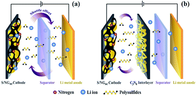 | ||
| Fig. 1 Schematics of the as-fabricated lithium sulfur batteries (LSBs) using sulfur-loaded NGae (S/NGae) as the cathode (a) without and (b) with the g-C3N4/CFP interlayer. | ||
The as-fabricated LSB using sulfur-loaded NGae with a finely tuned 4.2% nitrogen content (S/NGae) combined with the g-C3N4/CFP interlayer provides a specific capacity of 1271.5 mA h g−1 at an applied current of 0.1C (an increase of up to ca. 30% compared with the LSB without an interlayer). It also shows an excellent stability after 400 cycles with a capacity fading of 0.068% per cycle.
Experimental
Chemicals and materials
Graphite (<20 μm, Sigma-Aldrich), potassium permanganate (KMnO4, Carlo Erba), sodium nitrate (NaNO3, Ajax Finechem), sulfuric acid (H2SO4, 98%, QRec), hydrogen peroxide (H2O2, 30%, Chem-supply), polyvinylidene fluoride (PVDF, Mw ∼ 534![[thin space (1/6-em)]](https://www.rsc.org/images/entities/char_2009.gif) 000, Sigma-Aldrich), hydrazine hydrate (N2H4, 99%, Loba Chemie), sulfur (Merck), ethanol (99.9%, QRec), N-methyl-2-pyrrolidone (NMP, 99.5%, QRec), lithium nitrate (LiNO3, anhydrous, 99%, crystalline, Alfa Aesar), bis(trifluoromethane)sulfonimide lithium salt (LiTFSI, Sigma-Aldrich), 1,3-dioxolane (DOL, 99.5%, Alfa Aesar), 1,2-dimethoxyethane (DME, anhydrous, 99.5%, Sigma-Aldrich), and urea (98%, Sigma-Aldrich) were of analytical grade and used without further purification. Carbon fiber paper (CFP, SGL CARBON SE, Germany) was used as a substrate. Deionized water was purified by using a Milli-Q system (DI water, 15 MΩ cm, Millipore).
000, Sigma-Aldrich), hydrazine hydrate (N2H4, 99%, Loba Chemie), sulfur (Merck), ethanol (99.9%, QRec), N-methyl-2-pyrrolidone (NMP, 99.5%, QRec), lithium nitrate (LiNO3, anhydrous, 99%, crystalline, Alfa Aesar), bis(trifluoromethane)sulfonimide lithium salt (LiTFSI, Sigma-Aldrich), 1,3-dioxolane (DOL, 99.5%, Alfa Aesar), 1,2-dimethoxyethane (DME, anhydrous, 99.5%, Sigma-Aldrich), and urea (98%, Sigma-Aldrich) were of analytical grade and used without further purification. Carbon fiber paper (CFP, SGL CARBON SE, Germany) was used as a substrate. Deionized water was purified by using a Milli-Q system (DI water, 15 MΩ cm, Millipore).
Synthesis of graphene oxide (GO)
GO was prepared by a modified Hummers and Offeman method41 with our modifications.42–44 Briefly, 10 g graphite and 15 g NaNO3 were dissolved in H2SO4 (1000 ml) and stirred in an ice bath. When the temperature reached 20 °C, 80 g KMnO4 was slowly added to the mixture and stirred for 24 h. After the oxidation process, DI water (1000 ml) and H2O2 (300 ml) were subsequently added to the suspension and kept stirring for 24 h. Finally, the suspension was washed with DI water until neutral (pH 7) and dried at 60 °C.Synthesis of N-doped reduced graphene oxide aerogel (NGae)
Firstly, GO (200 mg) was dissolved in DI water (100 ml) and sonicated for 2 h. Various concentrations of hydrazine hydrate (N2H4: 0.25, 0.5, 1, and 2 M), a reducing agent, were added to the suspension. The as-prepared suspension was transferred to a Teflon-lined autoclave and heated at 110 °C for 24 h. After the hydrothermal process, the sample was washed with DI water several times. Finally, NGae was obtained after being freeze dried for 72 h. The final products were labeled 0.25 M NGae, 0.5 M NGae, 1 M NGae, and 2 M NGae indicating different concentrations of N2H4 used.Loading of sulfur into NGae (S/NGae)
Sulfur was loaded to NGae with different contents of nitrogen by a melt diffusion method. First, NGae powder was grinded with sulfur at a mass ratio of 20![[thin space (1/6-em)]](https://www.rsc.org/images/entities/char_2009.gif) :
:![[thin space (1/6-em)]](https://www.rsc.org/images/entities/char_2009.gif) 80, then transferred to a Teflon-lined autoclave, and heated at 155 °C for 6 h. The as-obtained powder (50 mg) was washed with ethanol (250 ml) and DI water (500 ml) to remove sulfur at the outer surface and dried at 50 °C overnight.
80, then transferred to a Teflon-lined autoclave, and heated at 155 °C for 6 h. The as-obtained powder (50 mg) was washed with ethanol (250 ml) and DI water (500 ml) to remove sulfur at the outer surface and dried at 50 °C overnight.
Preparation of the g-C3N4/CFP interlayer
Urea (5 g) was placed in a sealed ceramic boat and then transferred to a quartz tube furnace. The pyrolysis was carried out under a nitrogen atmosphere with a heating rate of 10 °C min−1 from room temperature to 600 °C and held for 4 h, obtaining g-C3N4 in yellow powder form. After that, g-C3N4 was mixed with NMP solvent and sonicated for 2 h to form a slurry. The slurry was cast onto carbon fiber paper (CFP) with a diameter of 2 cm at a mass loading of ca. 3.0 mg, dried at 60 °C, and used as the interlayer in LSBs.Morphological and structural characterization
The morphologies of the as-synthesized samples were characterized using Field-Emission Scanning Electron Microscopy (FE-SEM, JSM-7001F, JEOL Ltd.). The surface area and porous structures before and after sulfur loading were measured using a N2 adsorption/desorption technique (BELSORP-mini, MicrotracBEL Corp). The Brunauer–Emmett–Teller (BET) model was used to calculate the specific surface area of the samples. The thermal gravimetric analysis technique (TGA, STA PT1600, Linseis) was used to measure the amount of sulfur in the composite. The structural properties were evaluated using Raman spectroscopy (Senterra Dispersive Raman Microscope, Bruker). The surface compositions were characterized using X-ray photoelectron spectroscopy (XPS, Axis Ultra DLD, Kratos Analytical Ltd., with Al-Kα radiation (hν = 14![[thin space (1/6-em)]](https://www.rsc.org/images/entities/char_2009.gif) 866 eV)).
866 eV)).
The assembly of battery cells and electrochemical evaluation
The cathode electrode was prepared by mixing S/NGae, carbon black conductive additive, and PVDF binder in a ratio of 60![[thin space (1/6-em)]](https://www.rsc.org/images/entities/char_2009.gif) :
:![[thin space (1/6-em)]](https://www.rsc.org/images/entities/char_2009.gif) 30
30![[thin space (1/6-em)]](https://www.rsc.org/images/entities/char_2009.gif) :
:![[thin space (1/6-em)]](https://www.rsc.org/images/entities/char_2009.gif) 10 wt%, respectively and dissolved in NMP. The mixture was stirred for 24 h until homogenous. The as-obtained slurry was cast onto the CFP substrate via a casting machine and vacuum dried at 60 °C overnight. The as-cast sheet was cut into a circle with a diameter of 1.58 cm and then used as the cathode (the mass loading of sulfur is ca. 2.21–2.66 mg cm−2). The g-C3N4/CFP interlayer was inserted between the cathode and the hydrolyzed polyethylene separator (PE film, a thickness of 25 μm). 1 M LiTFSI dissolved in a mixture of DOL and DME (1
10 wt%, respectively and dissolved in NMP. The mixture was stirred for 24 h until homogenous. The as-obtained slurry was cast onto the CFP substrate via a casting machine and vacuum dried at 60 °C overnight. The as-cast sheet was cut into a circle with a diameter of 1.58 cm and then used as the cathode (the mass loading of sulfur is ca. 2.21–2.66 mg cm−2). The g-C3N4/CFP interlayer was inserted between the cathode and the hydrolyzed polyethylene separator (PE film, a thickness of 25 μm). 1 M LiTFSI dissolved in a mixture of DOL and DME (1![[thin space (1/6-em)]](https://www.rsc.org/images/entities/char_2009.gif) :
:![[thin space (1/6-em)]](https://www.rsc.org/images/entities/char_2009.gif) 1 v/v) with 2 wt% of LiNO3 additive was used as the electrolyte. A lithium chip was used as the anode. The coin-cell LSBs (CR2032) were fabricated in an argon-filled glovebox (MBraun) with H2O and O2 less than 1 ppm. The electrochemical performances were tested using galvanostatic charge/discharge (GCD) and cyclic voltammetry (CV) techniques using a NEWARE battery tester and Metrohm AUTOLAB potentiostat (PGSTAT302N), respectively. Note that the specific capacities were calculated based on the mass of the sulfur active material.
1 v/v) with 2 wt% of LiNO3 additive was used as the electrolyte. A lithium chip was used as the anode. The coin-cell LSBs (CR2032) were fabricated in an argon-filled glovebox (MBraun) with H2O and O2 less than 1 ppm. The electrochemical performances were tested using galvanostatic charge/discharge (GCD) and cyclic voltammetry (CV) techniques using a NEWARE battery tester and Metrohm AUTOLAB potentiostat (PGSTAT302N), respectively. Note that the specific capacities were calculated based on the mass of the sulfur active material.
Computational methods
All calculations were performed using the Vienna Ab initio Simulation Package (VASP).45,46 Projector augmented-wave (PAW) pseudopotentials were used to account for electron–ion interactions. The generalized gradient approximation (GGA)47 with the Perdew–Burke–Ernzerhof (PBE) functional48 was used to treat the exchange–correlation interaction between electrons. The empirical correction in Gimme's scheme (DFT-D3)49 was used to describe a long-range VDW interaction. The energy cut off was set to 520 eV and the 3 × 3 × 1 Monkhorst–Pack grid was used to sample the Brillouin zone. The convergence thresholds for full geometry optimizations were 10−5 eV and 1 × 10⁻⁴ eV Å−1 for the total energy and ionic force, respectively. g-C3N4 was modelled by using a 2 × 2 × 1 supercell layer. To avoid interaction between periodic images, the vacuum space was set to at least 20 Å.The interaction energy (Eint) of lithium sulfides on g-C3N4 is defined by the following equation (eqn (1)):
| Eint = E(Li2Sx–C3N4) − E(Li2Sx) − E(C3N4) | (1) |
Results and discussion
An FE-SEM image of 1 M NGae in Fig. 2a shows the 3D interconnected structure of reduced graphene oxide sheets. This morphology exhibits high porosity which is beneficial for electron transportation and electrolyte diffusion. After sulfur was loaded via the melt-diffusion method at 155 °C for 6 h (Fig. 2b), it was obviously seen that sulfur was successfully stored within the porous structure of NGae. Note that the morphology of 1 M NGae remains the same after sulfur was impregnated referring to its stable structure.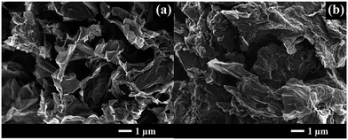 | ||
| Fig. 2 FE-SEM images of graphene aerogel reduced with 1 M N2H4 (namely 1 M NGae): (a) before and (b) after sulfur loading (S/1 M NGae). | ||
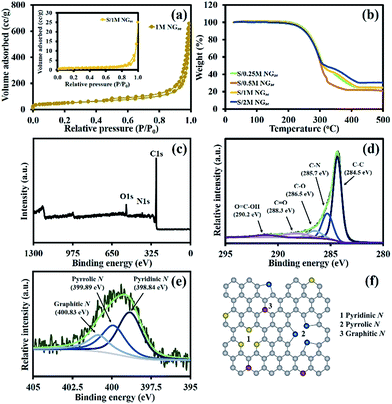
N2 adsorption/desorption measurements (Fig. 3a) are used to evaluate the pore volume and specific surface area (SSA) using BET calculations. The sorption isotherm of 1 M NGae can be identified as the combination of type I and II isotherms indicating that the material contains both macro- and mesopores.21 The BET specific surface areas of the samples before and after sulfur loading are 171.42 and 3.11 m2 g−1, respectively. Also, the pore volumes of those samples are 0.984 and 0.028 cm3 g−1, respectively. The decrease in the specific surface area and pore volume of the materials suggests that most of the pores are occupied by sulfur.
Thermogravimetric analysis (TGA) was carried out under a N2 atmosphere to evaluate the amount of sulfur inside NGae as shown in Fig. 3b. There are two regions of mass losses starting at 200 and 300 °C referring to the evaporation of confined sulfur from the macro- and mesopores of NGae, respectively. Sulfur in the mesopores has a stronger adsorption energy than sulfur loaded in the macropores resulting in a slower evaporation rate.51 According to the TGA results, the amounts of sulfur in S/0.25 M, S/0.5 M, S/1 M, and S/2 M NGae are 74.8, 78.2, 75.1, and 70.0 wt%, respectively.
The Raman spectra of the NGae produced using different concentrations of hydrazine hydrate are shown in Fig. S1 of the ESI.† The D band at 1350 cm−1 refers to the disordered structure of NGae, whilst, the G band at 1580 cm−1 relates to the E2g vibrational mode of sp2 graphitic carbon domains.52,53 The intensity ratios of D to G band (ID/IG) of 0.25 M, 0.5 M, 1 M, and 2 M NGae are 1.12, 1.08, 1.07, and 1.04, respectively. The G band intensity increases as a function of hydrazine concentrations, which is in good agreement with another previous study.54
The surface chemical composition of the as-prepared materials was evaluated by XPS. The XPS survey spectrum of 1 M NGae shows the peaks of C1s, N1s, and O1s at 285, 401 and 532 eV, respectively (see Fig. 3c)55 with the amount of C, N, and O being ca. 88.5, 4.2, and 7.3 atomic%, respectively. Fig. 3d shows the narrow scan C1s XPS of 1 M NGae, which can be deconvoluted into 5 peaks of C–C (284.5 eV), C–N (285.7 eV), C–O (286.5 eV), C![[double bond, length as m-dash]](https://www.rsc.org/images/entities/char_e001.gif) O (288.3 eV), and O
O (288.3 eV), and O![[double bond, length as m-dash]](https://www.rsc.org/images/entities/char_e001.gif) C–OH (290.2 eV) due to its functional groups.56,57 The narrow scan N1s spectrum of 1 M NGae is shown in Fig. 3e. Whilst, the N1s spectra of 0.25 M, 0.5 M, and 2 M NGae are shown in Fig. S2a–c of the ESI,† respectively. The N1s spectrum can be divided into three nitrogen-containing groups, which are pyridinic N, pyrrolic N, and graphitic N components at 398.84 eV, 399.89 eV, and 400.83 eV, respectively.58,59 A schematic model of these nitrogen groups is presented in Fig. 3f. The pyridinic N is a nitrogen atom, which provides lone pair electrons to substitute a carbon atom of the C6 ring and located at the edges of graphitic carbon.60,61 The strong interatomic attraction between pyridinic N and the positive charge of Li in LiSx results in the excellent PS adsorption ability of NGae.62–64 The pyrrolic N in the C5 ring provides a π system with two p-electrons which also improve the surface adsorption of NGae but not as strong as the pyridinic N groups.61 The graphitic N bonding via three sp2 carbon atoms on the graphitic carbon plane can introduce more electrons to enhance the electronic conductivity.65,66 Note that 1 M NGae possesses the highest pyridinic N (46.53%) as listed in Table 1 resulting in large binding sites for trapping polysulfides, which will help improving the cycling stability of LSBs.
C–OH (290.2 eV) due to its functional groups.56,57 The narrow scan N1s spectrum of 1 M NGae is shown in Fig. 3e. Whilst, the N1s spectra of 0.25 M, 0.5 M, and 2 M NGae are shown in Fig. S2a–c of the ESI,† respectively. The N1s spectrum can be divided into three nitrogen-containing groups, which are pyridinic N, pyrrolic N, and graphitic N components at 398.84 eV, 399.89 eV, and 400.83 eV, respectively.58,59 A schematic model of these nitrogen groups is presented in Fig. 3f. The pyridinic N is a nitrogen atom, which provides lone pair electrons to substitute a carbon atom of the C6 ring and located at the edges of graphitic carbon.60,61 The strong interatomic attraction between pyridinic N and the positive charge of Li in LiSx results in the excellent PS adsorption ability of NGae.62–64 The pyrrolic N in the C5 ring provides a π system with two p-electrons which also improve the surface adsorption of NGae but not as strong as the pyridinic N groups.61 The graphitic N bonding via three sp2 carbon atoms on the graphitic carbon plane can introduce more electrons to enhance the electronic conductivity.65,66 Note that 1 M NGae possesses the highest pyridinic N (46.53%) as listed in Table 1 resulting in large binding sites for trapping polysulfides, which will help improving the cycling stability of LSBs.
| Samples | N pyridinic (%) | N pyrrolic (%) | N graphitic (%) |
|---|---|---|---|
| 0.25 M NGae | 41.04 | 33.87 | 25.08 |
| 0.5 M NGae | 40.68 | 34.94 | 24.38 |
| 1 M NGae | 46.53 | 32.91 | 20.56 |
| 2 M NGae | 34.38 | 40.61 | 25.01 |
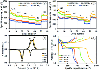
The GCD technique was used to evaluate the electrochemical performance of the as-assembled LSBs. Fig. 4a shows the specific capacities of LSBs using different cathodes without the interlayer at different applied current densities (0.1, 0.2, 0.5, 1, and 2C). Note that the C rate is based on the theoretical capacity of sulfur and 1C refers to ∼1675 mA g−1. The results show that S-loaded 1 M NGae provides the highest initial specific capacity of 1139.8 mA h g−1 at 0.1C but the capacity was rapidly dropped. When Li ions react with sulfur, the so-called polysulfide intermediates will diffuse into the electrolyte resulting in capacity decay and low specific capacity. After the g-C3N4/CFP interlayer was inserted (see the FE-SEM image, Raman spectrum, XRD pattern, and FTIR spectrum of g-C3N4 in Fig. S3a–d of the ESI,† respectively), the significant improvement in the electrochemical performance was clearly observed. The specific capacity of LSBs using S/0.25 M NGae, S/0.5 M NGae, S/1 M NGae, and S/2 M NGae with the g-C3N4/CFP interlayer is increased up to ca. 23–57% when compared with the LSB without the interlayer as shown by the results in Fig. 4b. Note, the specific capacity of the LSB using the CFP interlayer was compared with that using the g-C3N4/CFP interlayer in Fig. S4.† The CV in Fig. 4c shows a pair of redox peaks for the 1st to 5th cycles having the same peak shape and current indicating high stability of the as-fabricated LSB. Two cathodic peaks (I and II) at 2.3 and 2.0 V vs. Li/Li+ can be referred to the transformation of S into Li2Sn (4 ≤ n ≤ 8) and Li2S2/Li2S, respectively. The anodic peaks (III and IV) at 2.35 and 2.4 V vs. Li/Li+ can be attributed to the oxidation process of Li2Sn (n > 2) until polysulfides were completely consumed and S was eventually formed.67–69 The GCD profiles of the 1st cycle at 0.1C in Fig. 4d show voltage plateaus, which are in good agreement with the CV results.
To reveal the adsorption mechanism of PSs on the g-C3N4 surface, the first-principles density functional theory (DFT) calculation was performed. Highly soluble PS species of Li2S4, Li2S6 and Li2S8 were selected for simulation in this work. Fig. 5 shows the optimized structures of g-C3N4 and the adsorption of PSs on g-C3N4 obtained from the PBE-D3 calculations. The PS species do interact with the g-C3N4 surface via a lithium bond between the Li atom of PSs and the pyridinic N sites at the vacancies of the g-C3N4 plane. The adsorption interactions are strong so that the structures of g-C3N4 and the adsorbed PSs are significantly altered (see Fig. 5). The binding energies of Li2S4, Li2S6 and Li2S8 at the g-C3N4 calculated are −2.42, −2.18, and −2.03 eV, respectively. This result is in good agreement with another previous theoretical study.70 To further explain the adsorption of PS species at g-C3N4, the charge transfer mechanisms were studied using the Bader charge analysis method71 with the code developed by Henkelman's group.72 The charge transfer for the adsorption of Li2S4, Li2S6, and Li2S8 is 0.74, 0.38, and 0.13 e per molecule, respectively. Note, the faster charge transfer the higher binding energies of PSs at the g-C3N4.
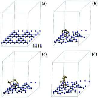 | ||
| Fig. 5 Optimized structures of (a) g-C3N4 and its interaction with (b) Li2S4, (c) Li2S6 and (d) Li2S8. | ||
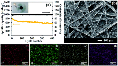
The stability test of the LSB using S/1 M NGae as the cathode with the g-C3N4/CFP interlayer is shown in Fig. 6a. After 400 cycles, the capacity fading of LSB is only 0.068% per cycle indicating excellent stability as well as a high coulombic efficiency of ∼100%. In addition, an inset image also shows that the fully charged LSB with 3 mg of the active S/1 M NGae material can supply electricity to a 3 V spinning motor for 9 min indicating the practical use of the as-fabricated LSB. An FE-SEM image of the g-C3N4/CFP interlayer after being used is shown in Fig. 6b. The EDS mapping of C, O, N, and S elements is shown in Fig. 6c–f, respectively. The EDS of the carbon atom can be referred to the carbon fiber paper substrate and carbon contained in the g-C3N4 compound. The oxygen element was detected due to the adsorbed organic electrolyte. Nitrogen refers to the nitrogen present in the g-C3N4 structure. The sulfur element was also found because of the PS species absorbing on the surface of the interlayer.
Conclusions
3D NGae with different nitrogen contents was produced by a hydrothermal reduction process of GO with hydrazine at different concentrations and employed as a host of sulfur in LSBs. At the same time, g-C3N4 produced by a hydrolysis process of urea was coated on the CFP substrate and used as the interlayer. The as-fabricated LSB using S-loaded NGae with a finely tuned 4.2% nitrogen content combined with the g-C3N4/CFP interlayer exhibits a high specific capacity of 1271.5 mA h g−1 and excellent cycling performance with a low capacity fading of 0.068% per cycle and a high coulombic efficiency of nearly 100% after 400 cycles. This battery may be practically used in high-energy applications.Acknowledgements
This work was financially supported by the Thailand Research Fund and Vidyasirimedhi Institute of Science and Technology (RSA5880043). Support from the Frontier Research Centre at VISTEC is also acknowledged.References
- C. Xu, Y. Wu, X. Zhao, X. Wang, G. Du, J. Zhang and J. Tu, J. Power Sources, 2015, 275, 22–25 CrossRef CAS.
- J. Zhang, Z. Dong, X. Wang, X. Zhao, J. Tu, Q. Su and G. Du, J. Power Sources, 2014, 270, 1–8 CrossRef CAS.
- X. Ji and L. F. Nazar, J. Mater. Chem., 2010, 20, 9821–9826 RSC.
- Y. V. Mikhaylik and J. R. Akridge, J. Electrochem. Soc., 2004, 151, A1969–A1976 CrossRef CAS.
- P. G. Bruce, S. A. Freunberger, L. J. Hardwick and J.-M. Tarascon, Nat. Mater., 2012, 11, 19–29 CrossRef CAS PubMed.
- G. He, X. Ji and L. Nazar, Energy Environ. Sci., 2011, 4, 2878–2883 CAS.
- Y. Wu, C. Xu, J. Guo, Q. Su, G. Du and J. Zhang, Mater. Lett., 2014, 137, 277–280 CrossRef CAS.
- Y. Yang, G. Zheng and Y. Cui, Chem. Soc. Rev., 2013, 42, 3018–3032 RSC.
- J. Shim, K. A. Striebel and E. J. Cairns, J. Electrochem. Soc., 2002, 149, A1321–A1325 CrossRef CAS.
- L. Xiao, Y. Cao, J. Xiao, B. Schwenzer, M. H. Engelhard, L. V. Saraf, Z. Nie, G. J. Exarhos and J. Liu, Adv. Mater., 2012, 24, 1176–1181 CrossRef CAS PubMed.
- G. Zhou, D.-W. Wang, F. Li, P.-X. Hou, L. Yin, C. Liu, G. Q. Lu, I. R. Gentle and H.-M. Cheng, Energy Environ. Sci., 2012, 5, 8901–8906 CAS.
- J. Zhang, J. Xiang, Z. Dong, Y. Liu, Y. Wu, C. Xu and G. Du, Electrochim. Acta, 2014, 116, 146–151 CrossRef CAS.
- S. Evers, T. Yim and L. F. Nazar, J. Phys. Chem. C, 2012, 116, 19653–19658 CAS.
- D.-W. Wang, G. Zhou, F. Li, K.-H. Wu, G. Q. Lu, H.-M. Cheng and I. R. Gentle, Phys. Chem. Chem. Phys., 2012, 14, 8703–8710 RSC.
- H. Wang, Y. Yang, Y. Liang, J. T. Robinson, Y. Li, A. Jackson, Y. Cui and H. Dai, Nano Lett., 2011, 11, 2644–2647 CrossRef CAS PubMed.
- G. Zhou, D.-W. Wang, F. Li, P.-X. Hou, L. Yin, C. Liu, G. Q. Lu, I. R. Gentle and H.-M. Cheng, Energy Environ. Sci., 2012, 5, 8901–8906 CAS.
- R. Chen, T. Zhao, J. Lu, F. Wu, L. Li, J. Chen, G. Tan, Y. Ye and K. Amine, Nano Lett., 2013, 13, 4642–4649 CrossRef CAS PubMed.
- S. Lu, Y. Cheng, X. Wu and J. Liu, Nano Lett., 2013, 13, 2485–2489 CrossRef CAS PubMed.
- Z. Li, Y. Jiang, L. Yuan, Z. Yi, C. Wu, Y. Liu, P. Strasser and Y. Huang, ACS Nano, 2014, 8, 9295–9303 CrossRef CAS PubMed.
- L.-B. Xing, K. Xi, Q. Li, Z. Su, C. Lai, X. Zhao and R. V. Kumar, J. Power Sources, 2016, 303, 22–28 CrossRef CAS.
- X. Gu, C.-j. Tong, C. Lai, J. Qiu, X. Huang, W. Yang, B. Wen, L.-M. Liu, Y. Hou and S. Zhang, J. Mater. Chem. A, 2015, 3, 16670–16678 CAS.
- A. Schneider, C. Suchomski, H. Sommer, J. Janek and T. Brezesinski, J. Mater. Chem. A, 2015, 3, 20482–20486 CAS.
- L. Qie, W.-M. Chen, Z.-H. Wang, Q.-G. Shao, X. Li, L.-X. Yuan, X.-L. Hu, W.-X. Zhang and Y.-H. Huang, Adv. Mater., 2012, 24, 2047–2050 CrossRef PubMed.
- J. Song, T. Xu, M. L. Gordin, P. Zhu, D. Lv, Y.-B. Jiang, Y. Chen, Y. Duan and D. Wang, Adv. Funct. Mater., 2014, 24, 1243–1250 CrossRef CAS.
- X.-G. Sun, X. Wang, R. T. Mayes and S. Dai, ChemSusChem, 2012, 5, 2079–2085 CrossRef CAS PubMed.
- F. Sun, J. Wang, H. Chen, W. Li, W. Qiao, D. Long and L. Ling, ACS Appl. Mater. Interfaces, 2013, 5, 5630–5638 CAS.
- J. Yang, J. Xie, X. Zhou, Y. Zou, J. Tang, S. Wang, F. Chen and L. Wang, J. Phys. Chem. C, 2014, 118, 1800–1807 CAS.
- L. Zhou, X. Lin, T. Huang and A. Yu, Electrochim. Acta, 2014, 116, 210–216 CrossRef CAS.
- F. Pei, T. An, J. Zang, X. Zhao, X. Fang, M. Zheng, Q. Dong and N. Zheng, Adv. Energy Mater., 2016, 6, 1502539 CrossRef.
- C. Zu, Y.-S. Su, Y. Fu and A. Manthiram, Phys. Chem. Chem. Phys., 2013, 15, 2291–2297 RSC.
- J.-Q. Huang, T.-Z. Zhuang, Q. Zhang, H.-J. Peng, C.-M. Chen and F. Wei, ACS Nano, 2015, 9, 3002–3011 CrossRef CAS PubMed.
- S.-H. Chung and A. Manthiram, J. Phys. Chem. Lett., 2014, 5, 1978–1983 CrossRef CAS PubMed.
- Y.-S. Su and A. Manthiram, Nat. Commun., 2012, 3, 1166 CrossRef PubMed.
- Q. Zeng, X. Leng, K.-H. Wu, I. R. Gentle and D.-W. Wang, Carbon, 2015, 93, 611–619 CrossRef CAS.
- H. M. Kim, J.-Y. Hwang, A. Manthiram and Y.-K. Sun, ACS Appl. Mater. Interfaces, 2016, 8, 983–987 CAS.
- T. Pettong, P. Iamprasertkun, A. Krittayavathananon, P. Sukha, P. Sirisinudomkit, A. Seubsai, M. Chareonpanich, P. Kongkachuichay, J. Limtrakul and M. Sawangphruk, ACS Appl. Mater. Interfaces, 2016, 8, 34045–34053 CAS.
- P. Iamprasertkun, A. Krittayavathananon, A. Seubsai, N. Chanlek, P. Kidkhunthod, W. Sangthong, S. Maensiri, R. Yimnirun, S. Nilmoung, P. Pannopard, S. Ittisanronnachai, K. Kongpatpanich, J. Limtrakul and M. Sawangphruk, Sci. Rep., 2016, 6, 37560 CrossRef CAS PubMed.
- P. Sirisinudomkit, P. Iamprasertkun, A. Krittayavathananon, T. Pettong, P. Dittanet and M. Sawangphruk, Sci. Rep., 2017, 7, 1124 CrossRef PubMed.
- W.-J. Ong, L.-L. Tan, Y. H. Ng, S.-T. Yong and S.-P. Chai, Chem. Rev., 2016, 116, 7159–7329 CrossRef CAS PubMed.
- X. Wang, K. Maeda, A. Thomas, K. Takanabe, G. Xin, J. M. Carlsson, K. Domen and M. Antonietti, Nat. Mater., 2009, 8, 76–80 CrossRef CAS PubMed.
- W. S. Hummers and R. E. Offeman, J. Am. Chem. Soc., 1958, 80, 1339 CrossRef CAS.
- Y. Sanguansak, P. Srimuk, A. Krittayavathananon, S. Luanwuthi, N. Chinvipas, P. Chiochan, J. Khuntilo, P. Klunbud, T. Mungcharoen and M. Sawangphruk, Carbon, 2014, 68, 662–669 CrossRef CAS.
- M. Sawangphruk, P. Srimuk, P. Chiochan, A. Krittayavathananon, S. Luanwuthi and J. Limtrakul, Carbon, 2013, 60, 109–116 CrossRef CAS.
- M. Sawangphruk, P. Srimuk, P. Chiochan, T. Sangsri and P. Siwayaprahm, Carbon, 2012, 50, 5156–5161 CrossRef CAS.
- G. Kresse and J. Furthmüller, Comput. Mater. Sci., 1996, 6, 15–50 CrossRef CAS.
- G. Kresse and J. Furthmüller, Phys. Rev. B: Condens. Matter Mater. Phys., 1996, 54, 11169–11186 CrossRef CAS.
- J. P. Perdew, K. Burke and M. Ernzerhof, Phys. Rev. Lett., 1996, 77, 3865–3868 CrossRef CAS PubMed.
- J. P. Perdew, M. Ernzerhof and K. Burke, J. Chem. Phys., 1996, 105, 9982–9985 CrossRef CAS.
- S. Grimme, J. Comput. Chem., 2006, 27, 1787–1799 CrossRef CAS PubMed.
- W. Tang, E. Sanville and G. Henkelman, J. Phys.: Condens. Matter, 2009, 21, 084204 CrossRef CAS PubMed.
- Z. Gong, Q. Wu, F. Wang, X. Li, X. Fan, H. Yang and Z. Luo, RSC Adv., 2016, 6, 37443–37451 RSC.
- D. Geng, Y. Chen, Y. Chen, Y. Li, R. Li, X. Sun, S. Ye and S. Knights, Energy Environ. Sci., 2011, 4, 760–764 CAS.
- Z.-H. Sheng, L. Shao, J.-J. Chen, W.-J. Bao, F.-B. Wang and X.-H. Xia, ACS Nano, 2011, 5, 4350–4358 CrossRef CAS PubMed.
- S. Yang, L. Zhi, K. Tang, X. Feng, J. Maier and K. Müllen, Adv. Funct. Mater., 2012, 22, 3634–3640 CrossRef CAS.
- D. Wei, Y. Liu, Y. Wang, H. Zhang, L. Huang and G. Yu, Nano Lett., 2009, 9, 1752–1758 CrossRef CAS PubMed.
- S. Some, Y. Kim, E. Hwang, H. Yoo and H. Lee, Chem. Commun., 2012, 48, 7732–7734 RSC.
- S. Some, P. Bhunia, E. Hwang, K. Lee, Y. Yoon, S. Seo and H. Lee, Chem.–Eur. J., 2012, 18, 7665–7670 CrossRef CAS PubMed.
- S. Niu, W. Lv, C. Zhang, F. Li, L. Tang, Y. He, B. Li, Q.-H. Yang and F. Kang, J. Mater. Chem. A, 2015, 3, 20218–20224 CAS.
- Z. Li, Z. Xu, X. Tan, H. Wang, C. M. B. Holt, T. Stephenson, B. C. Olsen and D. Mitlin, Energy Environ. Sci., 2013, 6, 871–878 CAS.
- X. Zhou, Q. Liao, J. Tang, T. Bai, F. Chen and J. Yang, J. Electroanal. Chem., 2016, 768, 55–61 CrossRef CAS.
- K. Han, J. Shen, S. Hao, H. Ye, C. Wolverton, M. C. Kung and H. H. Kung, ChemSusChem, 2014, 7, 2545–2553 CrossRef CAS PubMed.
- Y. Qiu, W. Li, W. Zhao, G. Li, Y. Hou, M. Liu, L. Zhou, F. Ye, H. Li, Z. Wei, S. Yang, W. Duan, Y. Ye, J. Guo and Y. Zhang, Nano Lett., 2014, 14, 4821–4827 CrossRef CAS PubMed.
- J.-J. Chen, R.-M. Yuan, J.-M. Feng, Q. Zhang, J.-X. Huang, G. Fu, M.-S. Zheng, B. Ren and Q.-F. Dong, Chem. Mater., 2015, 27, 2048–2055 CrossRef CAS.
- C. Ma, X. Shao and D. Cao, J. Mater. Chem., 2012, 22, 8911–8915 RSC.
- F. Sun, J. Wang, H. Chen, W. Li, W. Qiao, D. Long and L. Ling, ACS Appl. Mater. Interfaces, 2013, 5, 5630–5638 CAS.
- C. Wang, K. Su, W. Wan, H. Guo, H. Zhou, J. Chen, X. Zhang and Y. Huang, J. Mater. Chem. A, 2014, 2, 5018–5023 CAS.
- Q. Pang, D. Kundu and L. F. Nazar, Mater. Horiz., 2016, 3, 130–136 RSC.
- L. Ji, M. Rao, H. Zheng, L. Zhang, Y. Li, W. Duan, J. Guo, E. J. Cairns and Y. Zhang, J. Am. Chem. Soc., 2011, 133, 18522–18525 CrossRef CAS PubMed.
- N. Jayaprakash, J. Shen, S. S. Moganty, A. Corona and L. A. Archer, Angew. Chem., Int. Ed., 2011, 50, 5904–5908 CrossRef CAS PubMed.
- K. Liao, P. Mao, N. Li, M. Han, J. Yi, P. He, Y. Sun and H. Zhou, J. Mater. Chem. A, 2016, 4, 5406–5409 CAS.
- R. F. Bader, Atoms in Molecules, Wiley Online Library, 1990 Search PubMed.
- G. Henkelman, A. Arnaldsson and H. Jónsson, Comput. Mater. Sci., 2006, 36, 354–360 CrossRef.
Footnote |
| † Electronic supplementary information (ESI) available. See DOI: 10.1039/c7se00291b |
| This journal is © The Royal Society of Chemistry 2017 |

