Mechanistic investigation of a Ru-catalyzed direct asymmetric reductive amination reaction for a batch or continuous process scale-up: an industrial perspective†
Received
4th May 2017
, Accepted 8th August 2017
First published on 8th August 2017
Abstract
A comprehensive assessment of a Ru-catalyzed direct asymmetric reductive amination (DARA) reaction for producing an intermediate for an active pharmaceutical ingredient (API) was carried out. Experiments were conducted to investigate the impact of process parameters (such as reaction temperature, time, concentration, pressure, Ru-catalyst concentration, acid catalyst, and reagent stoichiometry) on chemo- and stereo-selectivity, and yield. An analysis of experimental data led to the development of a mechanistic mathematical model that was mathematically consistent with data from laboratory development and manufacturing campaigns. A combinatory approach outlined herein could be used to provide the optimum conditions for the DARA process. Furthermore, the feasible operating region was mapped out, which highlighted the complexity of the investigated chemistry and aided in developing the control strategy and regulatory submission package pertinent to this reaction. The efforts allowed the process to be successfully validated and scaled using a plug flow reactor (PFR) to manufacture 3200 kg of (S)-7,9-dimethyl-N-(2-methyl-2H-tetrazol-5-yl)-2,3,4,5-tetrahydro-1H-benzo[b]azepin-5-amine under current Good Manufacturing Practice (cGMP).
1. Introduction
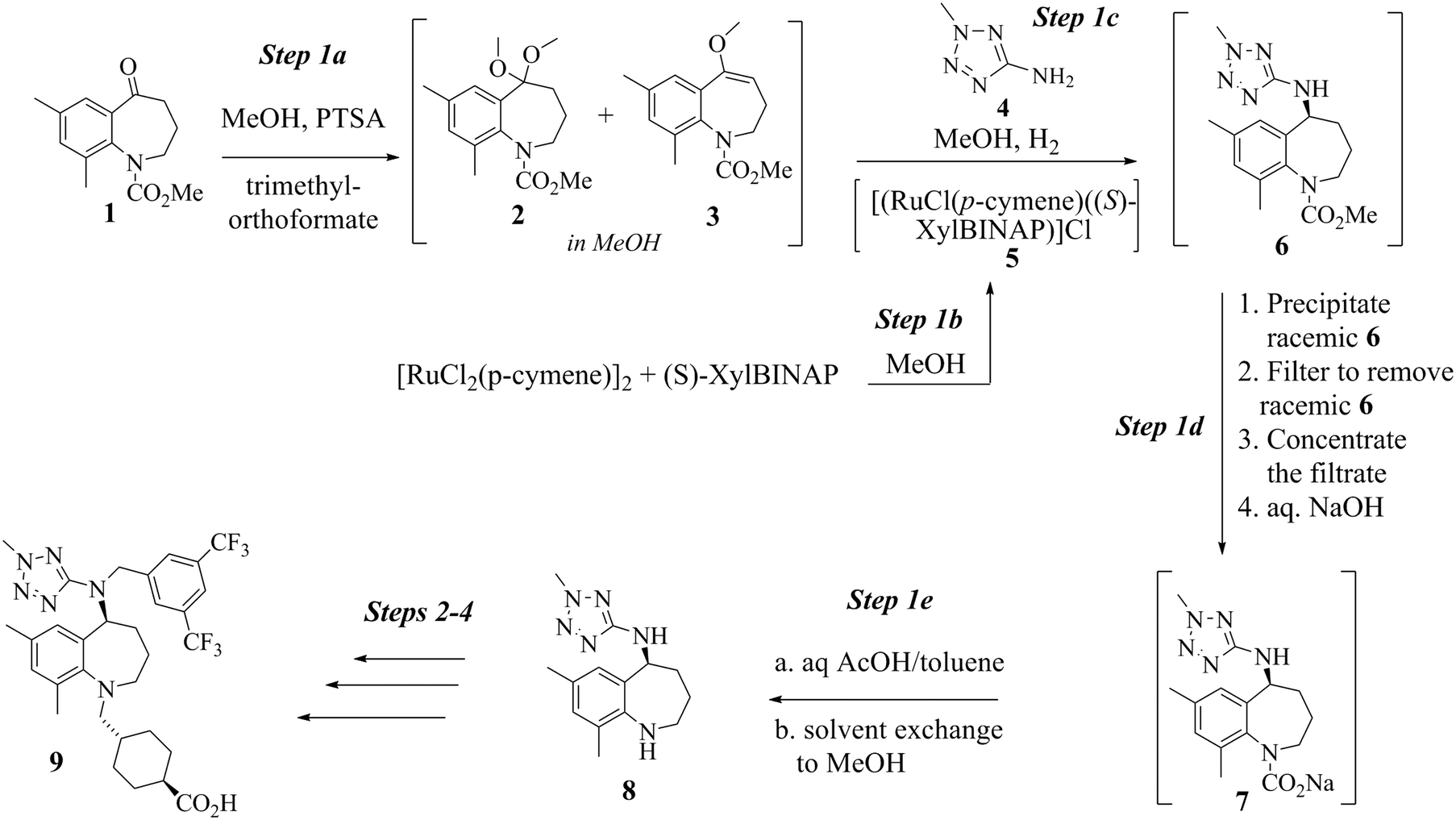
Scheme 1 shows the first step of the proposed registered sequence to produce evacetrapib (9). Evacetrapib (9) is an inhibitor of cholesteryl ester transfer protein (CETP), which was designed to increase high-density lipoprotein cholesterol (HDL-C) and, at the same time, reduce low-density lipoprotein cholesterol (LDL-C).1 Benzazepine (8) was the key intermediate required in the manufacture of 9 (see Scheme 1). Although several catalyst systems have been used in the past to convert an aldehyde or a ketone to an amine,2 one of the synthetic challenges faced by the research team was the construction of an amine moiety with high enantioselectivity. A method was developed based upon a direct asymmetric reductive amination (DARA) reaction mediated by the Ru-(S)-XylBINAP catalyst.3
 |
| | Scheme 1 Evacetrapib step 1 sequence. | |
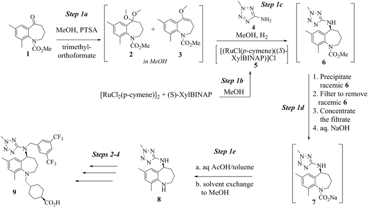
Conversion of 14 to 8 proceeds by way of a three-step sequence involving ketone (1) activation (step 1a), in situ imine formation and asymmetric reductive amination (step 1c), selective precipitation of racemic 6 followed by its removal by filtration and hydrolysis (step 1d) and decarbamation (step 1e) (see Scheme 1). In this event, 1 is reacted with trimethyl orthoformate in methanol in the presence of an acid catalyst, p-toluenesulfonic acid (pTSA), to produce a mixture of a dimethyl ketal 2 and a methyl enol ether 3. Since both species are capable of participating in the next step, reductive amination, the mixture is reacted with 2-amino-5-methyl tetrazole (4) at high temperature and high hydrogen pressure in the presence of a chiral, non-racemic, transition metal catalyst to afford 6. Scheme 1 depicts [RuCl2(p-cymene)]2 and (S)-XylBINAP as the asymmetric catalyst components that are reacted in step 1b to generate the active catalyst (5) required for the DARA reaction. Indeed this system is preferred due to reasons relating to manufacturability and high enantioselectivity for the desired optical isomer, although alternative systems, e.g. [NH2Me2][RuCl((S)-xylbinap)2(μ-Cl)3] and [Ir2Cl2(COD)2]-(S)-XylBINAP, have been used effectively on a large scale to provide 9 of acceptable quality. Additionally, the route through 2 was the preferred choice instead of conducting the DARA reaction using 1, in order to minimize the deleterious effects of liberated water on the reaction conversion and yield. It should be noted that during the DARA reaction, 1 could also be reduced to generate an alcohol (10) impurity (Fig. 1). There are other intermediates, such as an imine (11) and an enamine (12) (Fig. 1), which are formed during the DARA reaction before reacting away to form 6. Furthermore, a ketone dimer impurity (13) (Fig. 1) was identified to form post step 1d, primarily from residual 1 remaining at the end of the DARA step, impacting the quality of 8. The structures of the intermediates and impurities are given in Fig. 1. Overall, the DARA reaction (step 1c) is a crucial step forming a key intermediate (6) for the synthetic route of evacetrapib (9) and also generates several intermediates and impurities (e.g., 1, 3, 10, 11, 12, and 13) that could impact the quality downstream.
 |
| | Fig. 1 Structures of impurities (10 and 13) and intermediates (imine 11 and enamine 12). | |
A plethora of literature reports exists for the understanding of the mechanism for reduction of a ketone to an alcohol5–10 and an imine to an amine.6,11–13 However, there is sparse information in the literature providing guidance on the synthetic route or mechanistic understanding of reductive amination of ketones or ketals.14–18 Moreover, the latter studies do not offer much insights into the reaction rates of product or impurity formation. As mentioned above, the DARA reaction described in Scheme 1 proceeds with high chemo- and stereo-selectivity (94![[thin space (1/6-em)]](https://www.rsc.org/images/entities/char_2009.gif) :6) but also generates several intermediates and impurities (see Fig. 1), which needed to be controlled to achieve the final drug substance quality specifications downstream. To the best of our search capabilities, there is no report on the understanding of various steps involved in the conversion of a ketone, a ketal, an imine and an enol ether to an amine related to the system of interest herein. Additionally, the anticipated high metric ton demand of 8 required the development and establishment of a safe and robust manufacturing process with an impurity control strategy that would consistently provide 8 of desired quality. In light of the above, one of the main goals of this paper is to overcome the existing knowledge gap in DARA reactions involving either a ketal (2) or a ketone (1) by developing a semi-empirical mechanistic model.
:6) but also generates several intermediates and impurities (see Fig. 1), which needed to be controlled to achieve the final drug substance quality specifications downstream. To the best of our search capabilities, there is no report on the understanding of various steps involved in the conversion of a ketone, a ketal, an imine and an enol ether to an amine related to the system of interest herein. Additionally, the anticipated high metric ton demand of 8 required the development and establishment of a safe and robust manufacturing process with an impurity control strategy that would consistently provide 8 of desired quality. In light of the above, one of the main goals of this paper is to overcome the existing knowledge gap in DARA reactions involving either a ketal (2) or a ketone (1) by developing a semi-empirical mechanistic model.
Secondly, from a reactor design standpoint, hydrogenation reactions have been typically carried out in pharmaceutical industries using batch reactors on development and commercial scales. Although successful scale-up of processes using hydrogen at 5–10 MPa to manufacture cGMP intermediates and APIs (active pharmaceutical ingredients) is possible, high cost infrastructure investment is needed to ensure safety. Given the inherent risk of the hydrogenation reactions,19 recent developments have focused on continuous processing methodologies to conduct such reactions.20,21 Only a few research examples exist in the literature on successful implementation and scale-up of continuous reactors for high-pressure asymmetric reactions. Johnson et al.22 described in their research one such example of a fully continuous process including asymmetric hydrogenation operating at 7 MPa, producing 144 kg of product using a continuous plug flow reactor (PFR) of 73 L. Due to the projected demand of 9, a decision was made to run the commercial scale process using a PFR, in order to maximize the safety and reduce the cost of production over the life cycle of the drug. The success of running the DARA reaction was dependent on a thorough process understanding to predict the quality of 6 for a given combination of process parameters. It was desired to develop a mathematical model that would be predictive of the reaction outcome on the manufacturing scale.
Another motivation to develop the reaction kinetics model was to support regulatory submission by mapping out the feasible operating region and showing the predictability of the impact of various inputs on process outcomes. The model could help predict the DARA outcome in the event of process disturbances and input variation, in turn allowing for process adjustments and forward processing decisions. As reported by García-Muñoz et al.,23 such a graphical representation could go a long way to effectively communicate the interactions of several parameters for a complicated chemistry, such as DARA. Furthermore, due to the potentially large production demand of 9, this methodology could have a significant economic benefit by providing additional manufacturing flexibility (compared to data driven approaches) for batch acceptance criteria in the event of a process disturbance, based on expanded process understanding. The paper aims to discuss this methodology in detail.
To summarize, a thorough understanding of the DARA reaction (step 1c in Scheme 1) was required for key control of process impurities and its implementation in a commercial setting. For this paper, the main focus will be on the product (6) and two key impurities (1 and 10) that could impact the quality of 8 downstream. We report herein the development of a reaction kinetics model for the DARA reaction to establish the operationally feasible operating region and effects of multiple variables for this complex process chemistry to produce a high quality material. The model captures an understanding of the impact of process parameters (such as reaction temperature, time, catalyst, and substrate concentration) on the rates of formation of the product and impurities. Additionally, equipment mixing characteristics have been included in the model to verify that there was no significant impact of axial dispersion on conversion versus mean residence time. An illustrative case study of a high-volume intermediate in pharmaceutical manufacturing should present the readers with a methodology of using a combination of experimentation and mathematical models to successfully run the complicated chemistry in manufacturing and assist in the regulatory submission package.
2. Experimental results & discussion
The DARA reaction of interest herein could be influenced by a number of process-related variables. From a kinetics perspective, the reaction temperature and reaction time are the most obvious ones. However, there could be interactions of other process parameters (e.g. catalyst loading, pressure, etc.) that could impact the reaction outcome for impurities and the desired product. This section discusses the relevance of DARA process parameters that will then serve as a basis to develop the mechanistic understanding and reaction model.
2.1. Impact of reaction temperature & time
A screening study of the DARA reaction was completed to understand the impact of temperature and time on reaction conversion, impurity formation, and enantiomeric excess. In this study, five experiments were run at varying temperatures (from 110 to 150 °C) and reaction times (up to 6 hours), while keeping the pressure (4.5 MPa), the ratio of the substrate to catalyst (S/C) (1000:1), and the reaction concentration (2 L kg−1) constant. These experiments were conducted using 1, carrying it through step 1a before running it through the DARA step (refer to the ESI,† Table S1 for reaction trends for the DARA reaction conducted at different temperatures and times). The mass balance was very good (>95%) for most of the sampling points except at lower temperatures and reaction times. One reason for the discrepancy at lower temperatures and reaction times may be due to not accounting for all potential intermediates (e.g. imines, enamines, hemi-aminals, N,O-acetals, aminals, etc.), which are more prevalent at lower temperatures.
At any given temperature, the concentrations of the product (6) and the corresponding alcohol (10) increase continuously as a function of time, while the ketone (1) concentration exhibits a relative maximum (see Fig. 2a & b). This behavior in the ketone (1) trend is indicative of a series reaction, wherein 2 could hydrolyze to 1 (ref. 24) followed by the catalytic reduction of 1 to form 10 (ref. 5–10). Interestingly, at 150 °C, 1 is nearly consumed but it fails to form an equivalent amount of 10, i.e. only 48% molar yield of 10 was obtained when accounting for total 1 from incoming feed and water in the system (water content = 300 ppm). The experimental data suggest that 1 could also be consumed in a parallel reaction path; one possibility of (1) reacting with 4 to also form the DARA product14,15 (proceeding through formation of imine (11)/enamine (12) and other intermediates). The enol ether (3) profile also trends to a maximum before nearly being consumed. It is possible that initially some of the 2 can undergo de-alcoholysis to form 3. The enol ether (3) is ultimately converted to the main product 6via the same intermediates as 2. These observations will be useful to provide a rationale for developing the reaction mechanism for the DARA reaction of interest, which will be discussed later in section 3.1.
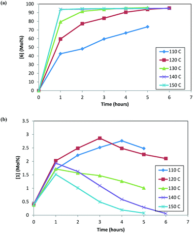 |
| | Fig. 2 (a) Reaction trends for [6] as a function of temperature. (b) Reaction trends for [1] as a function of temperature. | |
Fig. 3 shows the trends for the main product (6) and key impurities (unreacted 1 and 10) and also the enantiomeric excess differences after the DARA reaction has been run for 5 hours at different temperatures. It can be concluded that the conversion to 6 is much lower (∼70 mol%) and the unreacted 1 level is much higher (∼2.5 mol%) when the DARA reaction is conducted below 120 °C at the end of 5 hours (see Fig. 3a). At higher temperatures, compound 1 levels decrease (e.g. at 150 °C compound 1 levels are almost zero), while alcohol (10) levels increase due to the increase in the rate of ketal (2) hydrolysis to ketone at higher temperatures. Additionally, the enol ether (3) levels are well below 1 mol% at 5 hours above 120 °C (see ESI† Table S1).
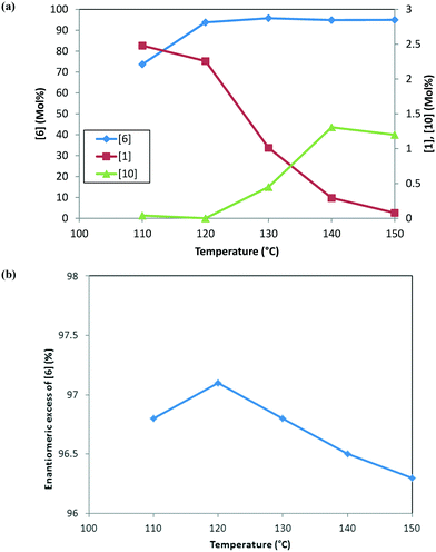 |
| | Fig. 3 (a) Reaction trends for [6] (primary axis) and [1] and [10] (secondary axis) as a function of temperature after 5 hours. (b) Trend for the enantiomeric excess of [6] as a function of temperature at 5 hours. | |
In order to develop a control strategy for the process-related impurities, spiking study experiments were conducted downstream (at step 1e) to test various impurity rejections. The enol ether impurity (3) was demonstrated to be rejected completely up to 5 mol%. Thus, a DARA reaction carried out for 5 hours and any temperature above 110 °C should be able to meet the specification for 3 at the end of the reaction. For unreacted 1, however, it was desired to minimize its amount at the end of the DARA reaction to less than 2.3 mol%; otherwise, it could lead to the undesirable impurity 13 (in step 1d) along with 10, at levels that could fail the final product specification. Clearly, with all other reaction parameters held constant for a reaction time of 5 hours, the temperature for the DARA reaction must be at or above 130 °C in order to meet the criteria of 6 passing the product specification downstream. The combination of: a) the process water specification (not more than 300 ppm in methanol for DARA reaction), b) the concentration (2.0 L kg−1), and c) unreacted 1 being less than 2.3 mol% will ensure that 10 and 13 will be always be below the maximum demonstrated rejection levels. Lastly, due to the chiral non-racemic catalyst used for DARA, (R) and (S) enantiomers of the products will be formed unequally, favoring the (S)-enantiomer. The measured enantiomeric excess was found to slightly decrease with an increase in temperature above 120 °C (see Fig. 3b), i.e. from 97% at 120 °C to 96.3% at 150 °C. Note that the slight decrease in enantiomeric excess at 110 °C (96.8%) is probably due to experimental and analytical variability and also due to the fact that the full conversions have not been reached when the sample was pulled at 5 hours. The decrease in enantiomeric excess primarily affects the downstream yield rather than impacting quality because the DARA reaction is followed by crystallization to provide a high enantiopurity product.
To summarize, unreacted 1 and 10 are the main impurities of concern during the DARA reaction, having implications on downstream rejection. On the industrial production scale, it was desirable to run this reaction at 135 °C and for 5 hours, at 2 L kg−1 and an S/C of 1000:1 to increase the process throughput efficiency and meet the impurity specifications.
2.2. Impact of reaction concentration
In an effort to understand the effect of reaction concentration on DARA reaction kinetics, four experiments were carried out starting with 1 under conditions of 130 °C, 4.5 MPa, an S/C of 1000:1 and varying methanol volumes (1.5, 2.0, 3.0, and 5.0 L kg−1) [see ESI† Table S2 for reaction trends for the DARA reaction conducted at different concentrations]. One reaction volume is defined as 1 L of solvent per kilogram of 1. Based on the experimental results, it can be concluded that the reaction concentration does not impact the enantiomeric excess for the DARA reaction. In order to understand the rates of the desired (conversion of 2 to 6) to the undesired (conversion of 2 to 10via1) reaction, a selectivity term was defined as the molar ratio of product (6) to alcohol (10) and calculated at different reaction concentrations (see Table 1). A dilute reaction condition leads to lower selectivity. For example, when the reaction dilution is increased by two and three times the selectivity decreased nearly two- and three-fold, respectively. The trends in our results are qualitatively consistent with the findings of Wisman et al.,9 who also reported a similar effect of dilution on the equilibrium conversion of asymmetric transfer hydrogenation of acetophenone, i.e. a two-fold increase in dilution increased the alcohol in their study by 21%. It is possible that a higher dilution brings in more water into the system, causing higher amounts of 1 to form via the hydrolysis of 2. Consequently, the product (6) yield will be reduced. Additionally, several complicated equilibria involving methanol exist during the reductive amination of ketones14 (Fig. 4), which could lead to a reduction in the rate of amine formation from 1, affecting selectivity. Thus, it can be concluded that the reaction concentration impacts the selectivity of 6 to 10 and needs to be incorporated into the reaction kinetics understanding.
Table 1 Molar ratio of product to alcohol as a function of reaction concentration for DARA reaction
| Reaction concentration (L kg−1) |
Product [6]:alcohol [10] (mol/mol) |
| 5 |
119 |
| 3 |
164 |
| 2 |
210 |
| 1.5 |
330 |
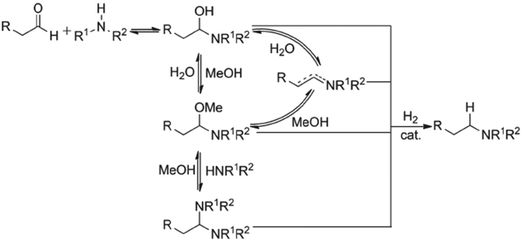 |
| | Fig. 4 Proposed mechanism for reductive amination of aldehydes. Reprinted from Raoufmoghaddam15 with permission. | |
2.3. Impact of catalyst loading
Hydrogenation reaction rates are typically affected by the catalyst loading. The literature has reported fractional-order catalyst order dependency, in the absence of an understanding of the catalytic cycles for a homogeneous hydrogenation reaction.25 To understand the effect of catalyst concentration on the rates of formation of the main product 6 and impurities, different experiments were conducted starting both with 2 and 1 substrates. This section will discuss the effect of catalyst loading on the reaction profile.
DARA reactions (step 1c) were conducted starting with isolated 2 at 120 °C, 5 MPa, and 5.0 L kg−1 at two different catalyst loadings, i.e. S/C of 1000:1 and 500:1. Fig. 5 shows the reaction profile for the main product (6), alcohol (10), and ketone (1) at the two catalyst loadings. The rate of product 6 formation is faster at a higher catalyst concentration (i.e. lower S/C). The alcohol (10) profile follows a similar trend to the main product (6); however, the difference is not as pronounced, given that only small amounts of 10 are formed at 120 °C. Additionally, 1 appears to be consumed at a slightly faster rate at a higher catalyst concentration (see Fig. 5b). These results indicate that the catalyst concentration affects the rates of formation of the main product 6 as well as the rates for ketone (1) consumption.
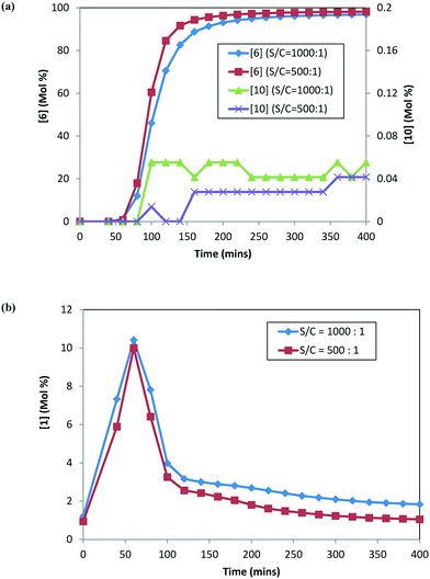 |
| | Fig. 5 DARA reaction starting with [2] at different catalyst loadings: (a) concentration–time profiles for [6] (primary axis) and [10] (secondary axis); (b) concentration–time profile for [1]. | |
In order to confirm these findings (specifically related to 1 and 10) and better understand the impact of catalyst loading on 10 formation, additional DARA reactions were conducted but this time starting with 25 g of isolated 1 directly (i.e. not subjecting 1 through step 1a prior to running DARA reaction) and 120 °C, 5 MPa, and 5.0 L kg−1 at different S/C ratios (1000:1, 500:1, and 100:1). Fig. 6 shows the concentration–time profile for 6 and 10 formation at different catalyst loadings. Interestingly, similar trends were obtained for the rates of 6 and 10 formation to those obtained previously when the reaction was conducted with 2, i.e. an increased catalyst concentration led to faster rates for both 6 and 10 formation. In fact, increasing the catalyst concentration ten-fold led to nearly double amounts of the product (6) and about one-and-half times more alcohol (10) formed after six hours into the reaction. It can be concluded from these results that the catalyst loading impacts the reaction selectivity for the desired (6) to the undesired (10) product.
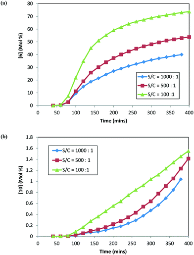 |
| | Fig. 6 DARA reaction starting with [1] at different catalyst loadings: (a) concentration–time profile for [6]; (b) concentration–time profile for [10]. | |
Thus, the catalyst loading is another variable that needs to be incorporated into a reaction model for this system to account for the rate of product conversion and the rate for impurity (unreacted 1 and 10) formation. Additionally, comparing the trends from Fig. 5 and 6, the rate of product 6 formation is slower when the reaction uses 1 rather than 2 as the starting material reagent, i.e. after 5 hours, 97% conversion to the desired product was obtained when starting with 2versus only 36% conversion when starting with 1 at S/C = 1000:1. Clearly, better throughput will be obtained on an industrial scale with 1 first converted to ketal (2) prior to carrying out the reductive amination, providing additional justification for the choice of the synthetic route, which is shown in Scheme 1.
2.4. Impact of reaction pressure
Hydrogenation reactions can be impacted by the reaction pressure because this parameter directly influences the effective moles of hydrogen that can bind to the catalyst. At a lower pressure and mixing rate in a conventional batch reactor, one may need to account for mass-transfer effects of hydrogen migrating to the active catalyst sites in addition to chemical kinetics of the hydrogenation reaction with the active hydrogen bound catalyst. On the other hand, the active catalytic sites can be saturated with hydrogen when the pressure is increased beyond a certain point, and only the chemical reaction kinetics will become rate determining afterwards. For an industrial process, it is desirable to operate in a kinetically controlled regime, where mass-transfer is not limiting the reaction rate. The conversion versus time in pipes-in-series reactors (industrial scale) matches the conversion versus time in well-mixed batch reactors (laboratory scale) that have kLa > 0.1 s−1.26 Although this paper does not quantify kLa in pipes-in-series reactors, existing literature proves that a 5 hour reaction is no more mass transfer limited than a well-mixed batch reactor. Future work will be needed to quantify kLa in pipes-in-series reactors, but it is a difficult challenge.
Experiments were conducted at four pressures (1.0, 3.0, 4.5, and 5.0 MPa) at 120 °C, 5.0 L kg−1, and S/C = 1000:1, starting with 1 and conducting step 1a prior to doing the DARA (see ESI† Table S3 for reaction trends as a function of varying pressure). Reaction conversion is clearly slower at 1.0 MPa, requiring almost a day to reach 90% conversion (Fig. 7). Beyond 3.0 MPa, reaction conversion appears to be similar within experimental uncertainties. These results suggest that mass transfer plays a role below 3.0 MPa, while the DARA reaction is kinetically controlled above 3.0 MPa, for the mixing rates considered herein. For the industrial scale, the reaction was run in a PFR at pressures ranging from 4.5–6.0 MPa, where mass transfer would not be a problem. Given this criterion, pressure dependency will be ignored from the reaction model and hydrogen will be treated as an excess reagent at all times.
 |
| | Fig. 7 Concentration–time profile for [6] as a function of varying pressure during DARA reaction. | |
2.5. Impact of 2-amino-5-methyltetrazole [4] stoichiometry
2-amino-5-methyltetrazole (4) is used as the other starting material reagent to carry out the amination reaction of the ketal (2) and enol (3) mixture formed in step 1a (Scheme 1). The amination reaction (step 1c) was designed such that 4 would not be a limiting reagent versus2. However, considering the manufacturing variability in the reagent charges and process parameters through the telescoped process (step 1a–step 1c), the situation where 4 is the limiting reagent is possible. Thus, it was necessary to understand the impact of the stoichiometry of 4 on the formation of 6 in the DARA reaction.
DARA reactions were conducted starting with 1 (processed through step 1a) under conditions of 135 °C, 5.2 MPa, an S/C of 1000:1, 2 L kg−1 and varying equivalents of 4 (0.9 and 0.98 equivalent versus ketone) [see the ESI,† Table S4 for reaction trends for the DARA reaction conducted with different stoichiometry of 4]. About 7% less conversion is obtained when the equivalency of 4 is reduced from 0.98 to 0.90, proving the criticality of the stoichiometry of 4 in meeting the product specification for the next step (step 1d). Additionally, the DARA reaction was comparable to the baseline run (i.e.4 equal to 1.0 equivalent, 135 °C) even at a lower temperature (120 °C), a higher dilution (5 L kg−1) and a lower pressure (4.5 MPa) when it was carried out with 1.1 eq. of 4 without forming new impurities. The experimental results suggest that the stoichiometry of 4 does not negatively influence the outcome of DARA reaction when in excess, but becomes a critical parameter when the equivalency of 4 is close to becoming that of a limiting reagent. A better understanding is necessary to assess the likelihood of DARA reaction meeting the product 8 specification under varying scenarios of the stoichiometry of 4, which will be discussed in a later section (see section 3.2.d and 4.1) in the context of a reaction model, which captures the effect of 4 when it becomes a limiting reagent.
2.6. Impact of p-toluenesulfonic acid (pTSA)
As mentioned in section 1, pTSA was used as an acid catalyst to promote step 1a. This acid will be carried into step 1c and can impact the DARA reaction outcome. DARA reactions were conducted starting with 2 and varying pTSA amounts under conditions of 135 °C, 5 MPa, 2 L kg−1 and an S/C of 1000:1. Prior to charging pTSA to 2 above, it was pre-mixed with trimethylorthoformate and then distilled under similar conditions to those employed at the end of step 1a to provide it with the same treatment as if coming from step 1a. Table 2 summarizes the reaction profile at the end of the DARA reaction after 5 hours. Interestingly, increasing the pTSA wt% appears to increase the conversion to the DARA product and also decrease the levels of 3 after 5 hours. These results suggest that both the ketal and enol ether conversions to imine/enamine (11/12) are acid catalyzed. Additionally, unreacted ketone (1) yields are slightly increased at higher pTSA wt%, possibly due to an increase in water brought in by pTSA, which may not all be completely removed by the distillation at the end of step 1a. The ranges for pTSA that have been explored herein are very broad and in reality for a manufacturing setting the variability around the pTSA charge will be much tighter, i.e. 0.45–0.55 wt%. Thus, for model discussion a narrower range for pTSA will be considered.
Table 2 DARA reaction trend and mass balance as a function of pTSA wt% (from step 1a)
| pTSA (wt%) |
Time (h) |
Mole% |
Mass balance (%) |
| [6] |
[10] |
[1] |
[3] |
[2] |
| 0 |
0 |
0.00 |
— |
0.00 |
0.00 |
100.00 |
100.00 |
| 5 |
57.61 |
0.43 |
0.15 |
16.81 |
14.07 |
89.06 |
| 0.25 |
0 |
0.00 |
— |
0.00 |
0.00 |
100.00 |
100.00 |
| 5 |
81.98 |
0.58 |
0.56 |
6.85 |
5.67 |
95.64 |
| 0.5 |
0 |
0.00 |
— |
0.00 |
0.00 |
100.00 |
100.00 |
| 5 |
92.43 |
0.53 |
0.78 |
2.45 |
2.35 |
98.53 |
| 0.75 |
0 |
0.00 |
— |
0.00 |
0.00 |
100.00 |
100.00 |
| 5 |
96.03 |
1.31 |
0.65 |
0.76 |
0.70 |
99.45 |
2.7. Experimental variability
Before proceeding with model development for the above experimental data, it was essential to quantify the error due to experimental variability. Several causes could lead to experimental variability between the runs, such as: 1) variability in reagent inputs or 2) accuracy of estimates for water content in the system, 3) variability in heat-up rates for the DARA reaction, and 4) analytical variability.
Three replicate experiments were conducted, starting with 1 and carrying it through step 1a before running it through step 1c. The conditions for carrying out DARA were 135 °C, S/C = 1000:1, 5.2 MPa, and 2 L kg−1 reaction. Table 3 summarizes the end of reaction profile after five hours, and it can be seen that fairly similar results were obtained for the DARA product (6), as well as the impurities. However, given the measurements for 6 are two orders of magnitude higher than those for unreacted ketone (1) or alcohol (10), a small difference in measurement for latter quantities can result in a significantly larger error (in %) compared to 6. Combined ketone (1) and alcohol (10) has a much lower error (in %) when compared individually. Therefore, for impurities, comparison of the model's results will be made on cumulative unreacted 1 and 10 concentrations.
Table 3 Experimental variability assessment for DARA end of reaction profile
| — |
Mole% |
Mass balance (%) |
| [6] |
[10] |
[1] |
[3] |
[2] |
[1] + [10] |
| Rep 1 |
94.75 |
1.47 |
0.09 |
0.96 |
1.42 |
1.56 |
98.69 |
| Rep 2 |
97.09 |
0.75 |
0.37 |
0.74 |
0.52 |
1.11 |
99.46 |
| Rep 3 |
97.02 |
0.83 |
0.51 |
0.69 |
0.72 |
1.34 |
99.77 |
| STDEV |
1.33 |
0.39 |
0.21 |
0.15 |
0.47 |
0.22 |
|
| Average |
96.29 |
1.01 |
0.32 |
0.80 |
0.88 |
1.34 |
|
3. Mathematical model
The previous section summarized the impact of key reaction variables – temperature, time, reaction concentration, catalyst loading, pressure, stoichiometry of 4, and pTSA on the rates of formation of 6 and impurities. Several rates may be affected when a reaction parameter is changed, thereby affecting the conversion of desired and undesired reactions, requiring a detailed mechanistic study.
A kinetics model for the mechanism consistent with the experimental data is very useful to predict the effect of different combinations of these parameters on maximizing the product yield and minimizing the impurities. With this in mind, a reaction kinetics model was developed for the DARA reaction with the available experimental data. The goal of the model was two-fold: 1) to maximize the desired conversion while meeting quality by optimizing the multivariate combination of seven parameters impacting the reaction and 2) to help map out the feasible operating region for achieving the quality attributes. Additionally, it was envisioned that a validated model may help describe the process risks and justify the choice of maximum and minimum tolerable ranges for parameters on the manufacturing scale for this reaction.
This section will describe in detail the assumptions and construct of the mechanistic model to capture the effect of parameters on reaction rates and selectivity. Finally, several examples will be discussed to verify the model.
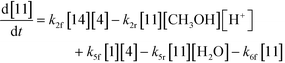
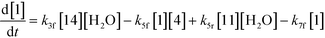
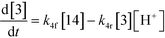
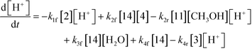
3.1. Mechanistic considerations
As discussed earlier, several papers provide an insight into various proposed mechanisms for the reductive amination of carbonyl compounds using a homogeneous catalyst, mostly Ru-complexes.2,8,9,13–15,27–29 However, to the best of our knowledge, no literature articles provide a mechanistic understanding of the reductive amination of ketals. One can extend the mechanistic understanding established for carbonyl compounds to gain an insight into the DARA reaction involved herein. A complete mechanism for this system would involve the understanding of several equilibrium reactions (e.g.Fig. 4) forming different intermediates, in conjunction with a mechanistic understanding of the complex catalytic cycle (e.g. Sandoval et al.8) during hydrogenation. Additionally, it should be pointed out that the reductive amination of ketals will be more complex mechanistically and includes several additional reactions promoted by the presence of the acid and Ru-complex catalyst in addition to the corresponding sets of reaction involving ketones, the latter being produced by the hydrolysis of ketals. Given the underlying complexities and limitations of the analytical techniques to identify all the intermediates and understand the catalytic cycle, a simplified mechanism was developed to account for the key product and impurities (see Fig. 8). The mechanism, which includes elementary and non-elementary reactions, was established to predict the reaction conversion and impurity formation (primarily 10 and unreacted 1) for the DARA reaction, which was of utmost interest to downstream processes for maximizing the yield and meeting the quality target.
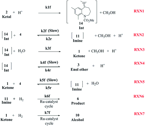 |
| | Fig. 8 Proposed reaction mechanism for DARA reaction starting with a ketal (Scheme 1). | |
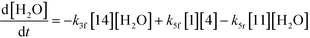
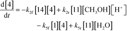
The first step of the proposed mechanism (RXN 1) involves protonation (due to pTSA coming from step 1a) of the ketal (2) to generate an intermediate species (14; Int). This Int (14) species can undergo three parallel reactions (RXNs 2, 3, and 4) with amine and water and rearrangement to form an imine (11), a ketone (1), and an enol ether (3), respectively. The ketone (1) can react with the amine (4) to form the imine (11) and liberate water (RXN 5).15 The imine (11) becomes involved in a complex catalytic cycle (ignored herein) involving reduction by molecular hydrogen to form the desired product 6 (RXN 6). An undesired reaction (RXN 7) can also occur involving the catalyst, wherein the ketone (1) can be reduced to form the alcohol (10). Thus, the proposed mechanism can account for by-products (1, 3, 10) and the desired product (6) starting with 2. Note that it can also account for a DARA reaction carried out with 1, wherein the first step of that reaction would involve 1 to form 11 by reacting with 4 (RXN 5) and then 11 propagating to various other species.
As a first pass, all the steps in this mechanism were assumed to be reversible and the rate constants were estimated using preliminary data (not shown herein). The outcome was that RXNs 1, 3, 6, and 7 were primarily favored in the forward direction, except RXNs 2, 4, and 5, which would therefore be the rate-limiting steps of this mechanism under normal operating conditions. Thus, the final version of the mechanistic construct for the empirical mathematical model described herein was based on Fig. 8, in lieu of the experimental data, even though RXNs 1 and 3 are likely highly reversible from a mechanistic chemistry perspective. The next topics will discuss in detail the mathematical framework of the kinetics model, estimation of model parameters, and model verification.
3.2. Reaction model
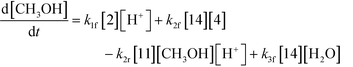
3.2.a Model framework.
An isothermal and isochoric batch reaction kinetics model was put forth for the mechanism proposed in Fig. 8 which consisted of species mass balances and resulted in a set of differential equations, as shown in eqn (1)–(11). It was assumed that the reaction order for each species was one except for hydrogen concentration, which was assumed to be zero order under the investigated conditions. This assumption for zero-dependency on hydrogen concentration was allowed because reaction pressures above 3.0 MPa have only slight differences in reaction kinetics (as shown earlier in section 2.4). Additionally, the industrial operation was planned above 3.0 MPa to get higher throughputs, making the model applicable for scale-up even with a pseudo zero order approximation for hydrogen. One could also argue that since methanol is the solvent for the reaction, the change in its concentration will not significantly impact reaction rates. However, we have not used a zero-order dependency in methanol because methanol could act both as a reagent and a solvent and as discussed earlier (in section 2.2) methanol amounts seem to affect the selectivity of desired to undesired reactions (i.e. product (6) versus alcohol (10) formation).| |  | (1) |
| |  | (2) |
| |  | (3) |
| |  | (4) |
| |  | (5) |
| |  | (6) |
| |  | (7) |
| |  | (8) |
| |  | (9) |
| |  | (10) |
| |  | (11) |
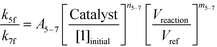
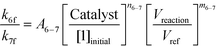
If one were to use only the above model then it will not be enough to explain the selectivity differences seen at various reaction concentrations and catalyst loadings (discussed in sections 2.2 and 2.3) even when we include reversibility for all reactions, because we have excluded the catalyst cycle and intermediate reactions involving solvent equilibria in the model. Thus, it was necessary to indirectly account for the effect on selectivity due to the reaction concentration and catalyst by including additional equations, i.e. three algebraic equations (eqn (12)–(14)) were included in the model, which were purely empirical.§ Other researchers in the past9,13 have also needed to use empirical relationships to model the reaction rates for the asymmetric transfer hydrogenation of ketones using a homogeneous ruthenium catalyst when not accounting for the catalytic cycle. Although the previous relationships were different from the ones used here because of different starting materials and neither accounting for the side reactions nor the selectivity differences, such empirical relationships somehow capture the experimental observations without necessarily needing to understand the catalytic cycle or every complex equilibrium involved in this chemistry.
| | 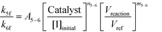 | (12) |
| |  | (13) |
| |  | (14) |
Thus, the final mathematical model consists of the set of eleven differential equations and three algebraic equations that will need to be simultaneously solved to obtain the time–concentration profile of various species. In order to use the model for quantitative predictions, an estimate of the model parameters is required, which is discussed in detail in the next section.
3.2.b Model parameter estimation.
DynoChem (version 2.0) was used to estimate the model parameters. Dynochem fits the reaction rate constant for forward reactions using the Arrhenius functionality (eqn (15)) at a reference temperature (chosen as 130 °C for this study). Note that in eqn (15), Ea is the activation energy, R is the universal gas constant, Tref is the reference temperature, T is the desired temperature at which the rate constant is to be determined, k is the pre-exponential factor for the reaction and kif is the actual rate constant for the forward ‘ith’ reaction at the temperature T. Additionally, in order to determine the rate constant for reverse reactions, Dynochem estimates the equilibrium constant, which can be defined by eqn (16), where Ki is the equilibrium constant for the ‘ith’ reaction, and kif and kir are the rate constants for the forward and reverse ‘ith’ reactions.| | 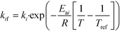 | (15) |
| |  | (16) |
In order to estimate the rate constants and Ea, we used the experimental data for the DARA reaction conducted with 2 at: 1) 120 °C (data presented in Fig. 5) [Exp #1] and 2) 140 °C (see the ESI,† Table S5) [Exp #2], at 5 MPa, 5.0 L kg−1, and an S/C of 1000:1. It should be noted that there was at least 40 min of time delay for the reactor contents to reach the actual temperature. In order to account for the heat-up time, we measured the internal temperature manually every minute for these experiments (see Fig. 9) and superimposed the temperature profile to build the temperature dependency into the rate constants. Lastly, the concentration profiles of 1, 2, 6, and 10 were used for the purpose of the model's parameter estimation.
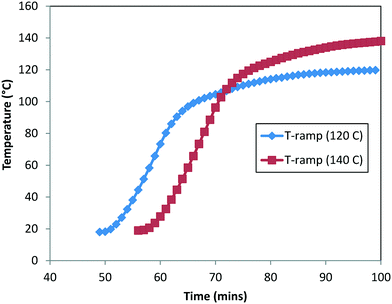 |
| | Fig. 9 Measured heat-up temperature–time profile for DARA at 120 °C (Exp #1) and 140 °C (refer to the ESI,† Table S5). | |
Additionally, we used the data from Fig. 5 at S/C = 1000:1 [Exp #3] and at S/C = 500:1 [Exp #4] and refit the rate constants (k5f, k6f, and k7f) separately to these two data sets (note that Vreaction/Vref = 1 for these experiments). With all other conditions being the same in these experiments, except the catalyst loading, one can obtain a linear relationship for a logarithmic plot for eqn (12) to eqn (14), thus determining A5–6, A5–7, A6–7, m5–6, m5–7, and m6–7. Lastly, we used the data from Fig. 5 at S/C = 1000:1 and the data from Table 1 (at 3 [Exp #5] and 2 L kg−1 [Exp #6]) at the same catalyst loading to again refit the rate constants (k5f, k6f, and k7f). One can estimate the last three parameters, n5–6, n5–7, and n6–7, knowing everything else in eqn (12)–(14). Thus, a minimum of six experiments were used to obtain the parameter estimates (see the ESI,† Table S6), which suffices to correlate the parameter dependency on various reaction variables. In reality one can use additional experiments to obtain better confidence in the parameter estimates but this is not necessary if the model can predict the outcomes of different experiments, as will be discussed in section 3.2.d.
Table 4 summarizes the rate constants for all the seven reactions considered in the model at 130 °C, S/C = 1000:1, 5 MPa, and 5 L kg−1 reaction. It appears that the initial rate of conversion of 2 to 14 species is very fast. Interestingly, based on the estimated rate constants (k4r nearly 3 times greater than k1f), the acid catalysis rates of RXN1 for 2 to 14 (k1f[2][H+]) will be three times slower compared to a similar concentration of RXN4 for 3 to 14 (k4r[3][H+]). For the three parallel reactions, involving the 14 species, it appears that the initial pseudo-first order rate is the slowest for RXN3 involving the formation of 1 (k3f[H2O] ∼7.41 min−1), followed by RXN4 involving the formation of 3 (k4f ∼1.00 × 10³ min−1) and lastly RXN2, involving the formation of 11 (k2f[4] ∼6.76 × 10³ min−1). Additionally, the reaction rates for 14 and 1 species with 4, i.e. RXN2 & RXN5, respectively, appear to be comparable given that initially both 14 and 1 will only be present in small amounts. However, comparing the rates for RXN6 and RXN7, i.e. hydrogenation of 11 and 1, respectively, it appears that the rate for the formation of 6 (k6f[11]) is quite high (by nearly 6 orders of magnitude) compared to the formation of 10 (k7f[1]), which is the undesired product. Thus, the main affinity of this reaction is to form 6 under these conditions, which is consistent with the experimental results.
Table 4 Summary of rate constants for individual reactions at 130 °C, S/C = 1000:1, 5 MPa, and 5 L kg−1
| Reaction # |
k
if
|
k
ir
|
| Value |
Units |
Value |
Units |
| 1 |
1.30 × 10⁴ |
L mol−1 min−1 |
|
|
| 2 |
1.10 × 10⁴ |
L mol−1 min−1 |
6.47 × 10⁷ |
(L mol−1)2 min−1 |
| 3 |
5.00 × 10² |
L mol−1 min−1 |
|
|
| 4 |
1.00 × 10³ |
1/min |
4.00 × 10⁴ |
L mol−1 min−1 |
| 5 |
1.40 × 10⁴ |
L mol−1 min−1 |
3.89 × 10⁸ |
L mol−1 min−1 |
| 6 |
4.10 × 10³ |
1/min |
|
|
| 7 |
3.00 × 10⁻³ |
1/min |
|
|
3.2.c Model fit test.
Parity plots comparing the concentrations of 6 and combined 1 and 10 (including and excluding heat-up transition data) obtained experimentally and via the model parameters for the five experiments discussed above in this section are shown in Fig. 10a–c. It can be seen that the data points are mainly concentrated along the diagonal (perfect match of model and experimental values), within experimental variability. Ignoring the heat-up transition data points from the parity plot (Fig. 10c) gives a better concentration of experimental and model data points along the diagonal compared with those including the heat-up transition data (Fig. 10b). This result can be explained because during heat-up there will be a higher amount of active intermediates, giving an artificially high 1 experimentally (see the ESI,† section 1.3). Thus, it appears that there is a lack of systematic bias in the model fit.
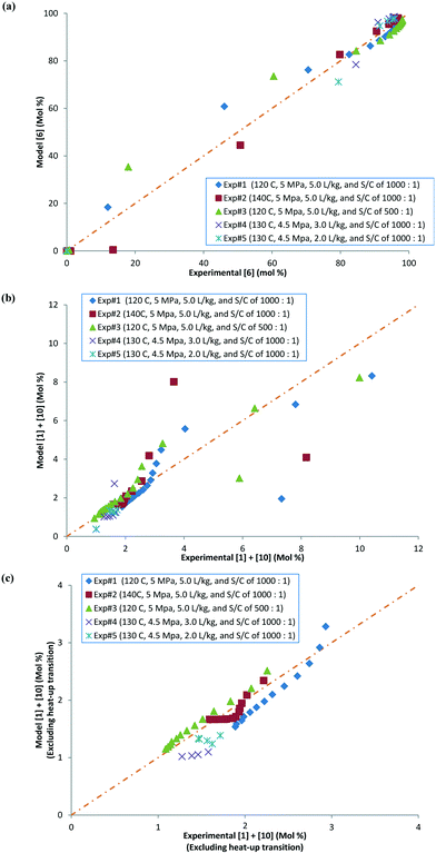 |
| | Fig. 10 (a) Parity plot comparing experimental and model values for [6] in mol%, (b) parity plot comparing experimental and model values for [1] + [10] in mol%, with heat-up transition data, and (c) parity plot comparing experimental and model values for [1] + [10] in mol%, excluding heat-up transition data. | |
To further confirm that the model fit is adequate and lacks a systematic bias, statistical testing was performed on the residuals for the predictions, with the residual defined by eqn (17).23 A goodness of fit t-test was performed to test the model bias to a two sided 97.5% confidence for the mean of the residual to contain zero [eqn (18), where ûr = mean of residual, tinv = t-statistic value at 97.5% confidence interval, N = total data points (=75), dfr = degree of freedom = N − 1, and σr = standard deviation of the residuals]. A histogram was constructed for the residuals using the 75 data points available for the experimentally measured 6 and combined 1 and 10 concentrations (see Fig. 11). For 6, the mean of the residual appears to be close to zero and the spread of the residual appears to be distributed around zero (see Fig. 11a), whereas for combined 1 and 10 the residual appears to have a mean close to zero but the spread of the residual appears to have a slight bias to the right of zero (see Fig. 11b). Fig. 11c shows that the histogram of the model residual excluding the heat-up transition data is distributed much better around zero. Since the model is intended to predict 6 and combined 1 and 10 concentrations after the reaction temperature has been reached, the model is deemed adequate for its intended use.
| | | Residual = Experiment–Model prediction | (17) |
| | | Bias Test: 0 to be contained in [ûr − tinv(dfr, 0.975)*σd/N0.5, ûr − tinv(dfr, 0.975)*σr/N0.5] | (18) |
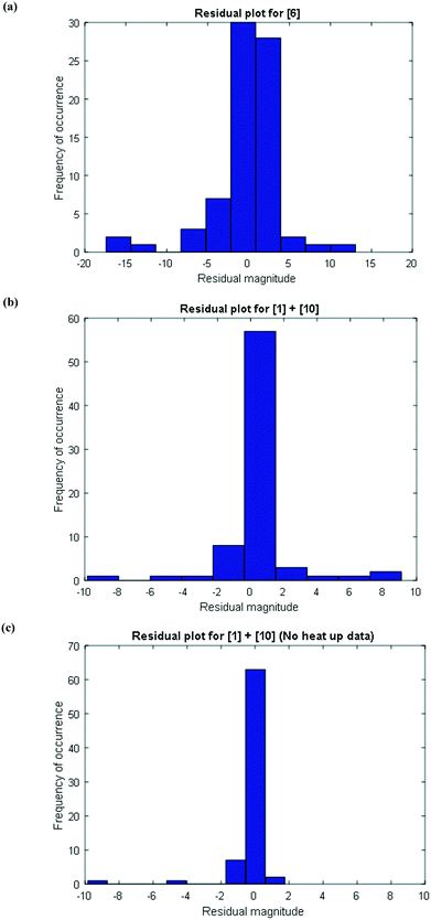 |
| | Fig. 11 Histogram of the distribution of the model residuals for (a) [6], (b) [1] + [10], including heat-up transition data, and (c) [1] + [10], excluding heat-up transition data. | |
3.2.d Model verification.
The reaction kinetics model for the DARA reaction was intended to enhance the understanding of the effects of relevant process parameters and predict the outcome of the DARA reaction during manufacturing under multiple process disturbances. However, model verification needed to be accomplished using independent experimental data sets that existed as a part of the process development activities to establish confidence in the model prior to its use for making prediction, as discussed in this section.
Several sets of experimental data presented earlier (not a part of the model fit exercise) and additional ones were used to test the model performance in predicting 6 and cumulative 1 and 10 yields, under uni-/multi-variate combination of input process parameters. Table 5 presents the experimental details with highlighted cells indicating the process parameter that was changed compared to baseline experiments. These situations could arise due to typical operational variability around process parameters in a manufacturing scenario. There are seven process parameters that could influence the outcome of DARA reaction, i.e., pTSA wt% (from step 1a), reaction temperature, time, concentration, S/C (catalyst loading), pressure, and 4 eq. For some of the experiments, the reaction profile was trended over several time points, whereas for other experiments, only one end sample was verified against the model. In all, 156 data points were available for verification from the 39 experiments, which should be plenty to provide confidence in the model's predictive capability.
Table 5 Experimental details for model verification. Greyed blocks represent changes in parameter value from baseline conditions
Exps 1–3 are denoted as baseline run condition replicates, against which a parameter change would be made to test the model's prediction. The range that has been tested for each of the variables (see Table 6) covers the 6-sigma range and beyond for a process parameter following quality by design guidelines for manufacturing,30 based on internal company standards.31,32 It should be noted that we have not implicitly accounted for reaction pressure and pTSA wt% in the reaction kinetics; however, the model should still be able to predict the reaction trends because the reaction rates are free of mass transfer above 3.0 MPa (see section 2.4) and we are only considering a very narrow range for pTSA wt% (see section 2.6).
Table 6 Process parameter range tested for model verification
| Process parameter |
Lower limit |
Upper limit |
| Temperature |
110 °C |
150 °C |
| Reaction time |
60 min |
1800 min |
| Reaction concentration |
1.39 L kg−1 |
6.00 L kg−1 |
| S/C loading |
100:1 |
1500:1 |
| Pressure |
3 MPa |
6 MPa |
| [4] eq. |
0.9 eq. versus1 |
1.1 eq. versus1 |
| pTSA wt% |
0.45 wt% |
0.55 wt% |
Some of the multivariate experiments were intentionally designed using the model to test if it could predict the feasible operating region that would meet the product quality attributes (determined during the process development drill via spiking and rejection studies of impurities). For example, Exp #21 was an extreme case, intended to give a low conversion (36%) failing product specification, while Exp #39 was another extreme where despite varying 6 parameters it was still expected to meet the product quality (89% conversion). The model helped design the experiments efficiently and successfully captured these extreme cases amongst other data, as seen from the parity plots presented in Fig. 12 for 6 and combined 1 and 10 mol%. Most of the data points are scattered uniformly along the diagonal (within experimental + analytical + model variability) with the concentrations having been tested from 0–98 mol% for 6 and 0–90 mol% for 1 and 10. The few outlying points arise due to sampling during the heat-up ramp, where the model is limited in making accurate predictions, as discussed previously. However, the model's utility is not impacted as it is more geared towards predicting the profiles once reaction temperatures have been attained. Additionally, the model prediction appears tighter at lower values of 6 because these data points correspond to the product for the DARA reaction conducted with 1 rather than due to sampling during the heat-up ramp.
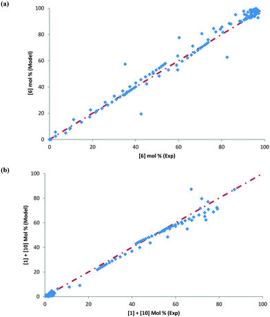 |
| | Fig. 12 Parity plot confirming model verification for (a) [6] mol% and (b) [1] + [10] mol%. | |
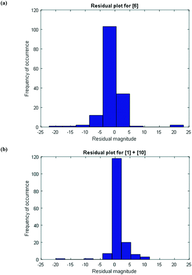
To further provide confidence that the model is acceptable, a histogram was constructed for the residuals using the 156 data points (see Fig. 13). As can be seen, the mean of the residual appears to be very close to zero and the spread of the residual also appears to be distributed around zero for both the concentrations of 6 and combined 1 and 10, confirming a lack of any obvious bias due to the model.
 |
| | Fig. 13 Histogram of the distribution of the model residuals for the (a) product [6] and (b) impurities [1] + [10]. | |
To summarize, for the first time to the best of our findings, the reaction kinetics model proposed herein for a DARA reaction is deemed structurally correct across a broad range of data sets and captures the complexity of the reaction. The DARA reaction could be influenced by seven input parameters, whose effects are all captured by the model for the manufacturing ranges of these parameters. This exercise has provided us with a very powerful tool to achieve our objectives laid out earlier in this paper, i.e. map out the feasible operating region of DARA operation under different combinations of processing parameters and use the model to help guide control strategy formulation at manufacturing, as will be discussed in the next section.
4. Model application and extension
This section focuses on the use of the reaction model to map out the feasible operating region and also develop control strategies and a decision tree for successful continuous operation of the DARA reaction at scale. Different scenarios will be discussed pertaining to manufacturing situations that could lead to passing/failing the product specifications. The model can be used to develop visual ways of communicating outcomes resulting from varying process perturbations.
4.1. Probability maps – initial step to mapping the feasible operating region and design space
García-Muñoz et al.23 have recently published a methodology to map out the feasible operating region, followed by a geometric projection exercise to determine the design space for a given process using mathematical models. Using their language, the “design space” is an operational envelope that allows manufacturing at a given condition to meet products of acceptable quality, backed by scientific understanding of the process. These authors describe the methodology to construct probability maps, which provide a substitute to the complex mathematics of the model, making it easy to communicate the design space. Given the advantages of this methodology, probability maps were constructed for the reaction model developed herein for the DARA reaction.
As mentioned earlier in section 3.2.d, the model was tested against several multivariate combinations of seven process parameters. However, the reaction pressure and pTSA wt% will not be explored to build probability maps because these parameters do not greatly alter the reaction outcome under the desirable ranges tested. For visualization purposes, probability maps were constructed for any two parameters at a given time keeping others constant, i.e. a total of 10 maps would suffice for the DARA reaction to represent its entire feasible operating region. To generate a probability map, experimental plus analytical variability (€exp+ana) and any model bias (€bias) need to be included in the model prediction (ŷmodel), as shown in eqn (19). Each of the uncertainty sources considered in this work was described by assuming a normal distribution. A Monte Carlo simulation33 was used to estimate the probability of meeting the desired product specification, i.e. greater than 88 mol% for the reaction considered here.
| | | ŷactual = ŷmodel + €exp+ana + €bias | (19) |
Several interesting conclusions can be drawn from the probability maps for the DARA reaction, as shown in Fig. 14, made using MATLAB R 2015a. Firstly, these graphs help us correlate the extent of interaction of combinations of parameters with product outcome. Varying parameters in a certain combination can have a strong influence on the feasible operating region to an extent that there is close to zero probability of meeting the product specification under those conditions, e.g. reaction temperature below 120 °C and reaction concentration less than 2 L kg−1 (Fig. 14a). On the other hand, there are certain parameter combinations that do not have any influence on the reaction outcome with the probability of meeting product quality attributes close to one, e.g. varying reaction concentration from 1–8 L kg−1 and catalyst loading from 500:1 to 1500:1, and keeping all other parameters at the baseline conditions will pass with >95% certainty for the entire range tested herein (Fig. 14e). Additionally, from these plots it can also be concluded that the reaction temperature is one of the most influential process parameters that may require critical control in manufacturing. Thus, one can assess the rigor of control required for various parameters in manufacturing to a certain extent by using this approach.
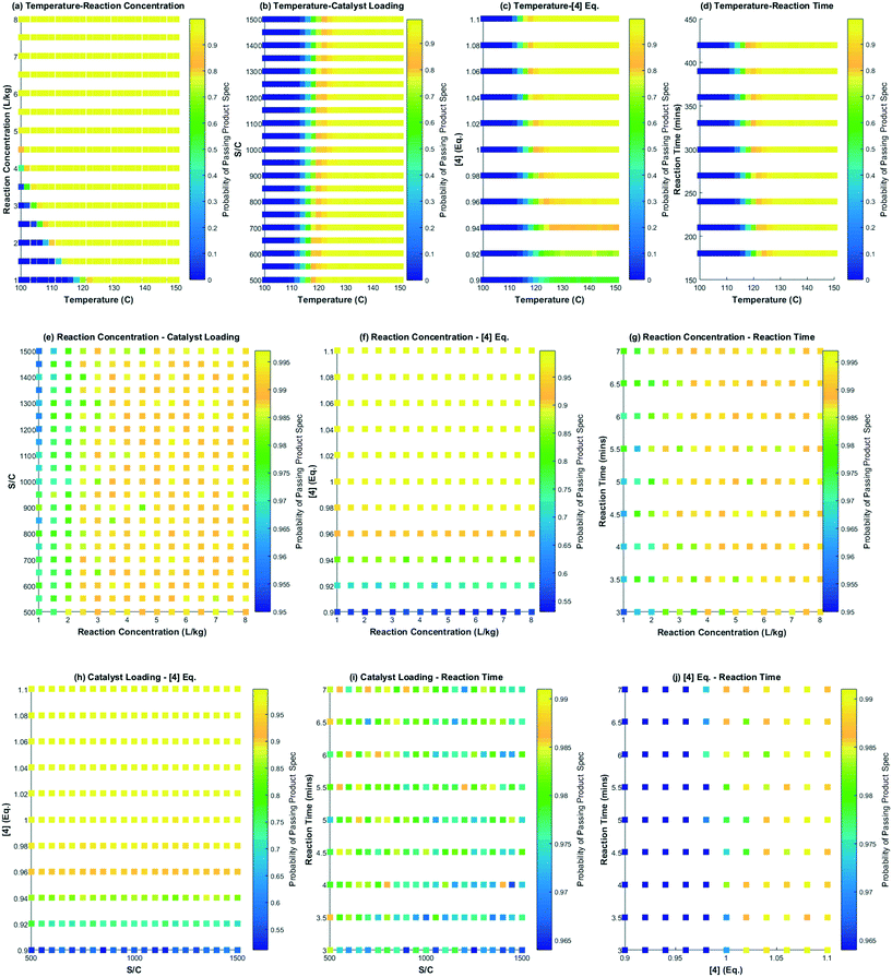 |
| | Fig. 14 Probability maps for the feasible operating region showing the effect of two variables at a time on passing the product specification; (a) temperature and reaction concentration, (b) temperature and catalyst loading, (c) temperature and [4] eq., (d) temperature and reaction time, (e) reaction concentration and catalyst loading, (f) reaction concentration and [4] eq., (g) reaction concentration and reaction time, (h) catalyst loading and [4] eq., (i) catalyst loading and reaction time and, (j) [4] eq. and reaction time. The colormap legend for each scatter plot assigns the probability of passing the quality attribute. | |
Secondly, these plots can be used directly in regulatory submission documents to help justify meeting of the quality requirements for a uni-/multi-variate perturbation in process parameters in a manufacturing scenario, thereby, indirectly serving to justify the impurity control strategy for the reaction. One could also conduct a similar exercise for the impurities (1, 10) (not shown here), knowing its tolerable limits in downstream steps. Without a reaction model and probability maps, one would have to conduct numerous experiments to defend the feasible operating region.
Lastly, probability maps can provide insights into optimization strategies for maximizing production efficiencies, such as the product yield and cycle time. Depending on the confidence and risk that one is willing to take, a geometric projection can be included in a regulatory submission document rather than a conventional rectangular box design.23 This former strategy may allow manufacturing to justify the choice of forward processing a batch in case of deviation from target values for process parameters. Fig. 15 shows a pictorial representation of this concept considering the probability map for temperature and reaction concentration. Clearly, the geometric projection increases the region that provides more flexibility for an acceptable batch (with probability >98% to meet product specification) versus the traditional rectangular box design approach.
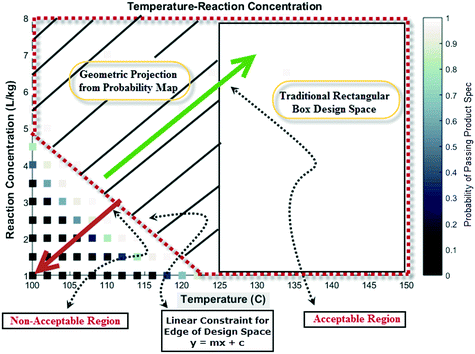 |
| | Fig. 15 Pictorial representation of a geometric projection of the probability map (design space) versus traditional box design space for additional manufacturing flexibility. | |
4.2. Continuous plug flow reactor dynamics
The actual DARA step was planned to run in a plug flow reactor on the manufacturing scale, requiring one to understand the axial dispersion of the PFR in conjunction with the reaction kinetics. Additionally, as there would be two feed streams into the PFR inlet – from step 1a and the catalyst solution, one needs to also understand the impact of flow rate variability of the feed pumps on the reactor performance. There is an inherent operational risk of affecting product quality in the event of a catalyst pump shutdown or fluctuations in its flow rate. Thus, one needs to better understand the effect of these situations to develop a decision plan on the commercial production scale. This section describes the modeling approach and assumptions made to conduct the risk assessment.
The kinetics model presented in section 3.2.a was considered in conjunction with the axial dispersion (D/μL) determined to be 0.002 for the commercial scale reactor, i.e. near plug-flow behavior (refer to the ESI† for additional details). However, eqn (8)–(10) were ignored from this assessment and replaced by constant concentrations for the respective species, i.e. proton, methanol, and water do not change their concentrations because they are present in excess or act as catalysts. The PFR residence time was 5 hours. Any variability in the flow rate of the catalyst solution would impact its concentration entering the PFR; however, it would have a minimal impact on the residence time.
The simulation is implemented as starting with no reactants in the PFR, and then flowing in the substrate and catalyst into the reactor without imposing any fluctuation for twice the residence time (to reach steady state in the absence of fluctuations). Fluctuations in the concentration of the catalyst is then implied because the flow rate for the catalyst pump is likely to have the greatest variability being about 3 orders of magnitude lower than the substrate. The flow rate data for the catalyst pump was time-averaged over various intervals using actual manufacturing data from a campaign run. Clearly, the catalyst pump had a severe instantaneous variability in delivering the solution at a desired flow-rate (see Fig. 16). Thus, it was critical to understand the impact of catalyst pump variability on the reaction outcome. For illustration purposes, 30 min time averaging was selected with a standard deviation (σ) of nearly 20%. The input catalyst feed was programmed to oscillate with an amplitude of 40% (2σ variability) and a time period of 30 min. A finely divided grid comprising 901 points for the time element and 201 points for the reactor length element was used for discretization.
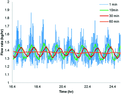 |
| | Fig. 16 Time averaged flow rate of the catalyst solution pump from manufacturing data. | |
As shown in Fig. 17a and b, the catalyst feed pump variability has a minimal impact on the conversion, i.e. conversion fluctuates within 0.3%. This matches very well the campaign data, which produced nearly 3200 kg of 6 and fluctuated within 0.5% for every lot that was run. Thus, this example illustrates the usefulness of understanding the reactor dynamics coupled with the kinetics to accurately predict production outcomes.
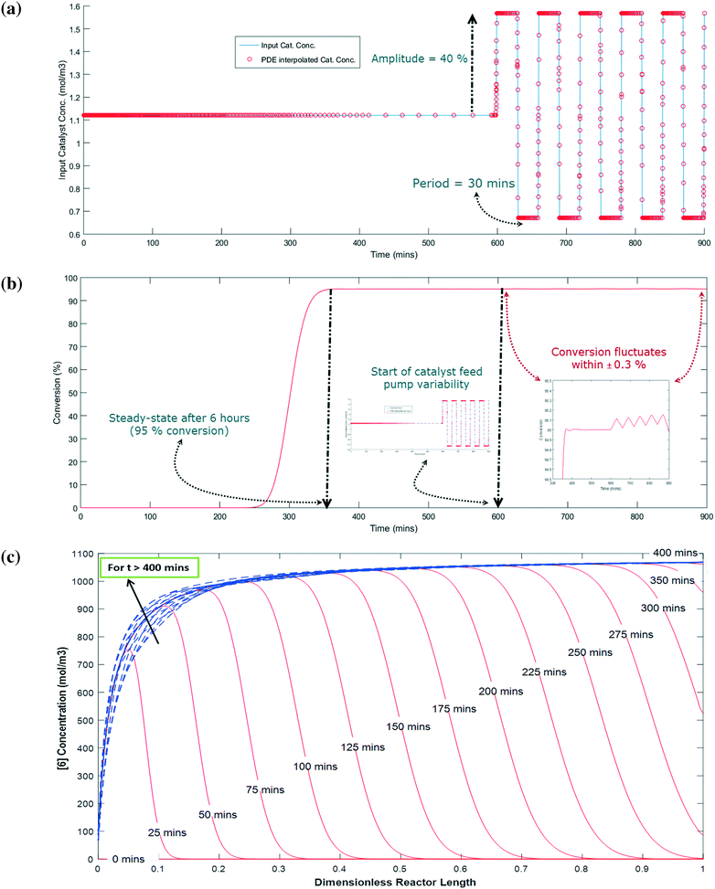 |
| | Fig. 17 (a) Input catalyst concentration profile for PFR with PDE interpolated overlay that will oscillate with 40% amplitude for every 30 minutes in either direction from steady-state, (b) output result for input fluctuations, and (c) profile of [6] (mol m−3) along the length of the reactor for a given time with solid red lines corresponding to t ≤ 400 min and dashed blue lines corresponding to t > 400 min. | |
Fig. 17c shows the concentration profile for 6 along the dimensionless reactor length at various times. When the reaction time is less than the residence time (i.e. 5 hours), the concentration of 6 steadily builds up with time at a given position in the PFR. For example, at 20% of the reactor length, 6 is only at 10% of its steady state value after 50 min and nearly 90% of its steady state value after 75 min. Interestingly, at a time greater than 400 min, 6 has a fluctuation in its concentration profile up to the first 40% length of the reactor, which corresponds to the catalyst feed pump variability (at t > 600 min). However, fluctuations are damped out for reactor length >40%, giving stable conversions at the outlet of the PFR (Fig. 17b). Thus, through this exercise one can get informative knowledge of the time–position profile of 6 in the PFR by simultaneously characterizing the reaction kinetics and axial dispersion that can help to understand the process dynamics for a process upset (e.g. pump set point drift). Including axial dispersion in the model confirmed that it did not have a significant impact on conversion versus time. Conversion versus time in the PFR is nearly the same as in the batch; therefore the reactor can be considered a plug flow reactor. However, if a continuous reactor that had higher axial dispersion had been used, then the impact on conversion versus time could have been significant and the model would quantify the difference.
5. Conclusion
A Ru-catalyzed direct asymmetric reductive amination reaction was studied thoroughly with successful process scale-up of an intermediate to manufacture a drug substance. An experimental rich uni-variate approach allowed the understanding of the impact of seven process parameters (reaction temperature, time, concentration, pressure, acid catalyst, Ru-catalyst, and reagent stoichiometry) on reaction yield, enantioselectivity and reaction selectivity. This screening exercise also ensured that there would be no mass-transfer limitations at scale-up and allowed a choice of the optimum conditions to maximize the product yield and purity. In order to understand the multi-variate interactions of the DARA process parameters with the reaction performance due to manufacturing variability, a semi-empirical mechanism was postulated which was consistent with data. This mechanism shares a new understanding of different reactions involved for a DARA reaction starting with either a ketone (1) or a ketal (2). A mathematical semi-empirical model was developed to quantitate various reaction rates and the selectivity of the product to various impurities under a given combination of process parameters. The model captured the effect of reaction concentration and catalyst loading on the selectivity of the desired product to impurities, without needing to understand the full details of the homogeneous catalytic cycle or accounting for all chemical equilibria involving the solvent. The model was verified against a number of experiments that varied multiple process parameters simultaneously. Reasonable predictions were realized for concentrations of the main product (6) and the ketone (1) and alcohol (10) impurities, thereby giving confidence in using it for optimizing the processing conditions. The model was very useful in developing methodologies for conducting a risk-based analysis, i.e. predicting the feasible operating region through probability maps and inclusion of axial dispersion in the reaction kinetics to understand the PFR performance in manufacturing. The model prediction and construction of probability maps were justified on the industrial scale in conjunction with the experimentally driven approach to optimize certain reaction parameters, e.g. reaction temperatures are changed from 120 to 135 °C for the validation campaign in order to optimize the yield and attain a better impurity control strategy. The methodologies presented herein using the DARA reaction, as an illustrative example, can be extended to other drug substance processes.
Conflicts of interest
There are no conflicts to declare.
Acknowledgements
The authors would like to thank Jeffrey C. Roberts, Jonas Buser and Adam McFarland (Eli Lilly and Company) for providing valuable analytical inputs related to online and offline HPLC and NMR analysis. We are grateful to Shankar Vaidyaraman (Eli Lilly and Company) for his inputs and suggestions related to the incorporation of PFR dynamics along with the reaction model. We acknowledge the efforts of Sathish Boini for help with the ketone and ketal synthesis and for providing inputs to the DARA reaction. The authors would like to sincerely acknowledge Scott Frank (Eli Lilly and Company) for his inputs related to the reaction mechanism. We are grateful to Takao Saito and Yutaka Okamura (Takasago International Corporation) for their guidance and inputs in laboratory and commercial development to achieve a successful validation campaign. We thank Bret Huff for initiating and sponsoring the flow chemistry and modeling efforts in development at Eli Lilly and Company. Finally, we would like to thank the management of both Eli Lilly and Takasago International Corporation for their utmost support throughout development and manufacturing stages to enable experimentation and development of mathematical models for this project.
References
- A. Sahebkar, L. E. Simental-Mendía, F. Guerrero-Romero, J. Golledge and G. F. Watts, Efficacy and safety of Evacetrapib for modifying plasma lipids: A systematic review and meta-analysis of randomized controlled trials, Curr. Pharm. Des., 2016, 22, 595–608 CrossRef CAS PubMed.
- R. P. Tripathi, S. S. Verma, J. Pandey and V. K. Tiwari, Recent development on catalytic reductive amination and applications, Curr. Org. Chem., 2008, 12, 1093–1115 CrossRef CAS.
- K. Mashima, K. H. Kusano, N. Sato, Y. I. Matsumura, K. Nozaki, H. Kumobayashi, N. Sayo, Y. Hori and T. Ishizaki, Cationic BINAP-Ru(II) Halide Complexes: Highly Efficient Catalysts for Stereoselective Asymmetric Hydrogenation of .alpha.- and .beta.-Functionalized Ketones, J. Org. Chem., 1994, 59, 3064–3076 CrossRef CAS.
- R. K. Vaid, S. K. Boini, C. A. Alt, J. T. Spitler, C. E. Hadden, S. A. Frank and E. D. Moher, Synthesis of Methyl 7,9-Dimethyl-5-oxo-2,3,4,5-tetrahydro-1H-benzo[b]azepine-1-carboxylate and its analogues, Synthesis, 2014, 46, 2463–2470 CrossRef CAS.
- S. Hashiguchi, A. Fujii, J. Takehara, T. Ikariya and R. Noyori, Asymmetric transfer hydrogenation of aromatic ketones catalyzed by chiral Ruthenium (II) complexes, J. Am. Chem. Soc., 1995, 117, 7562–7563 CrossRef CAS.
- R. Noyori and S. Hashiguchi, Asymmetric transfer hydrogenation catalyzed by chiral ruthenium complexes, Acc. Chem. Res., 1997, 30, 97–102 CrossRef CAS.
- E. J. Corey, R. K. Bakshi, S. Shibata, C. P. Chen and V. K. Singh, A stable and easily prepared catalyst for the enantioselective reduction of ketones. Applications to multistep syntheses, J. Am. Chem. Soc., 1987, 109(77925), 7925–7926 CrossRef CAS.
- C. A. Sandoval, T. Ohkuma, K. Muñiz and R. Noyori, Mechanism of asymmetric hydrogenation of ketones catalyzed by BINAP/1,2-Diamine-Ruthenium(II) complexes, J. Am. Chem. Soc., 2003, 125, 13490–13503 CrossRef CAS PubMed.
- R. V. Wisman, J. G. de Vries, B.-J. Deelman and H. J. Heeres, Kinetic studies on the asymmetric transfer hydrogenation of acetophenone using a homogeneous ruthenium catalyst with a chiral amino-alcohol ligand, Org. Process Res. Dev., 2006, 10, 423–429 CrossRef CAS.
- M. Yoshimura, S. Tanaka and M. Kitamura, Recent topics in catalytic asymmetric hydrogenation of ketones, Tetrahedron Lett., 2014, 55, 3625–3640 CrossRef.
- T. C. Nugent and M. El-Shazly, Chiral amine synthesis – recent developments and trends for Enamide reduction, reductive amination, and Imine reduction, Adv. Synth. Catal., 2010, 352, 753–819 CrossRef CAS.
- S. Kobayashi and H. Ishitani, Catalytic enantioselective addition to imines, Chem. Rev., 1999, 99, 1069–1094 CrossRef CAS PubMed.
- D. G. Blackmond, M. Ropic and M. Stefinovic, Kinetic studies of the asymmetric transfer hydrogenation of imines with formic acid catalyzed by Rh-Diamine catalysts, Org. Process Res. Dev., 2006, 10, 457–463 CrossRef CAS.
- V. I. Tararov, R. Kadyrov, T. H. Riermeier and A. Borner, A scrutiny on the reductive amination of carbonyl compounds catalyzed by homogeneous Rh(I) Diphosphane complexes, Adv. Synth. Catal., 2002, 344, 200–208 CrossRef CAS.
- S. Raoufmoghaddam, Recent advances in catalytic C–N bond formation: a comparison of cascade hydroaminomethylation and reductive amination reactions with the corresponding hydroamidomethylation and reductive amidation reactions, Org. Biomol. Chem., 2014, 12, 7179–7193 CAS.
- J. M. Humphrey, E. P. Arnold, T. A. Chappie, J. B. Feltenberger, A. Nagel, W. Simon, M. Suarez-Contreras, N. J. Tom and B. T. O'Neill, Diastereoselective Synthesis of 2,3,6-Trisubstituted Piperidines, J. Org. Chem., 2009, 74, 4525–4536 CrossRef CAS PubMed.
- H. Heaney, M. T. Simcox, A. M. Z. Slawin and R. G. Giles, Lanthanide Triflate catalysed reactions of acetals with primary amines and cascade cyclisation reactions, Synlett, 1998, 640–642 CrossRef CAS.
- A. Trejo,
et al., Design and synthesis of 4-Azaindoles as inhibitors of p38 MAP Kinase, J. Med. Chem., 2003, 46, 4702–4713 CrossRef CAS PubMed.
-
J. A. Barton and P. F. Nolan, Runaway reactions in batch reactors, I. Chem. E. Symposium Series No. 85, IChemE Safety & Loss Prevention Special Interest Grouphttps://www.icheme.org/communities/subject_groups/safety%20and%20loss%20prevention/resources/hazards%20archive/~/media/Documents/Subject%20Groups/Safety_Loss_Prevention/Hazards%20Archive/S085%20-%20Exothermic%20Reactors/S85-28.pdf Search PubMed.
- S. G. Newman and K. F. Jensen, The role of flow in green chemistry and engineering, Green Chem., 2013, 15, 1456–1472 RSC.
- M. Baumann and I. R. Baxendale, The synthesis of active pharmaceutical ingredients (APIs) using continuous flow chemistry, J. Org. Chem., 2015, 11, 1194–1219 CAS.
- M. D. Johnson, S. A. May, J. R. Calvin, J. Remacle, J. R. Stout, W. D. Diseroad, N. Zaborenko, B. D. Haeberle, W.-M. Sun, M. T. Miller and J. Brennan, Development and scale-up of a continuous, high-pressure, asymmetric hydrogenation reaction, workup, and isolation, Org. Process Res. Dev., 2012, 16, 1017–1038 CrossRef CAS.
- S. García-Muñoz, C. V. Luciani, S. Vaidyaraman and K. D. Seibert, Definition of design spaces using mechanistic models and geometric projections of probability maps, Org. Process Res. Dev., 2015, 19, 1012–1023 CrossRef.
- M. M. Achmatowicz, J. G. Allen, M. M. Bio, M. D. Bartberger, C. J. Borths, J. T. Colyer, R. D. Crockett, T.-L. Hwang, J. N. Koek, S. A. Osgood, S. W. Roberts, A. Swietlow, O. R. Thiel and S. Caille, Telescoped process to manufacture 6,6,6-Trifluorofucose via diastereoselective transfer hydrogenation: Scalable access to an inhibitor of Fucosylation utilized in monoclonal antibody production, J. Org. Chem., 2016, 81, 4736–4743 CrossRef CAS PubMed.
- R. V. Chaudhari, A. Seayad and S. Jayasree, Kinetic modeling of homogeneous catalytic processes, Catal. Today, 2001, 66, 371–380 CrossRef CAS.
- M. D. Johnson, S. A. May, B. Haeberle, G. R. Lambertus, S. R. Pulley and J. R. Stout, Design and comparison of tubular and pipes-in-series continuous reactors for direct asymmetric reductive amination, Org. Process Res. Dev., 2016, 20, 1305–1320 CrossRef CAS.
- A. H. Éll, J. B. Johnson and J.-E. Bäckvall, Mechanism of ruthenium-catalyzed hydrogen transfer reactions. Evidence for a stepwise transfer of CH and NH hydrogens from an amine to a (cyclopentadienone)ruthenium complex, Chem. Commun., 2003, 1652–1653 RSC.
-
J. S. M. Samec, Ruthenium-catalyzed hydrogen transfer involving amines and imines. Mechanistic studies and synthetic applications, PhD Thesis Stockholm University, April 2005 Search PubMed.
- C. Li, B. Villa-Marcos and J. Xiao, Metal-BrØnsted acid cooperative catalysis for asymmetric reductive amination, J. Am. Chem. Soc., 2009, 131, 6967–6969 CrossRef CAS PubMed.
- K. Pramod, M. A. Tahir, N. A. Charoo, S. H. Ansari and J. Ali, Pharmaceutical product development: A quality by design approach, Int. J. Pharm. Invest., 2016, 6(3), 129–138 CrossRef PubMed.
- J. D. Mitchell, K. Abhinava, K. L. Griffiths, B. McGarvey, K. D. Seibert and S. Sethuraman, Unit operations characterization using historical manufacturing performance, Ind. Eng. Chem. Res., 2008, 47, 6612–6621 CrossRef CAS.
- K. D. Seibert, S. Sethuraman, J. D. Mitchell, K. L. Griffiths and B. McGarvey, The use of routine process capability for the determination of process parameter criticality in small-molecule API synthesis, J. Pharm. Innov., 2008, 3, 105–112 CrossRef.
-
J. Fonseca, C. Mares, M. Friswell and J. Mottershead, Review of parameter uncertainty propagation methods in structural dynamic analysis, Proceedings of ISMA2002 - Volume IV, Leuven (Belgium), Setember 16-18th 2002, pp. 1853–1859 Search PubMed.
Footnotes |
| † Electronic supplementary information (ESI) available. See DOI: 10.1039/c7re00055c |
| ‡ To be considered as primary co-authors. |
| § Note that Vref = 5 L kg−1 is chosen herein. |
|
| This journal is © The Royal Society of Chemistry 2017 |
Click here to see how this site uses Cookies. View our privacy policy here. 
 *a,
Tohru
Yokozawa‡
b,
Tetsuya
Yamamoto
b,
Hikaru
Nakajima
b,
Matthew C.
Embry
a,
Radhe
Vaid
a,
Carla V.
Luciani
a,
Sze-Wing
Wong
a,
Martin
Johnson
a and
Eric D.
Moher
a
*a,
Tohru
Yokozawa‡
b,
Tetsuya
Yamamoto
b,
Hikaru
Nakajima
b,
Matthew C.
Embry
a,
Radhe
Vaid
a,
Carla V.
Luciani
a,
Sze-Wing
Wong
a,
Martin
Johnson
a and
Eric D.
Moher
a