 Open Access Article
Droplet evaporation characteristics on transparent heaters with different wettabilities†
Suhan Lee‡
a,
Dong-Ik Kim‡b,
Young-You Kimc,
Sung-Eun Parkd,
Gyuseok Choid,
Yoonkap Kim*d and
Han-Jung Kim *b
*b
aConvergence Medical Devices Research Center, Gumi Electronics & Information Technology Research Institute (GERI), Gumi 39253, South Korea
bCenter for Integrated Smart Sensors (CISS), Korea Advanced Institute of Science and Technology (KAIST), Daejeon 34141, South Korea. E-mail: hjkim0321@kaist.ac.kr
cDepartment of Physics, Kongju National University, Gongju 32588, South Korea
dConvergence Materials & Parts Technology Research Center, Gumi Electronics & Information Technology Research Institute (GERI), Gumi 39171, South Korea. E-mail: yoonkap@geri.re.kr
First published on 22nd September 2017
Abstract
To develop more effective defogging/deicing (or anti-fogging/anti-icing) devices based on transparent heaters, it is necessary to investigate droplet evaporation on the heater surfaces. However, the characteristics of this evaporation process have not yet been reported. Here, we present the evaporation characteristics of water droplets and their evaporation rates on various transparent heaters (based on metal mesh, indium tin oxide thin film, and Ag nanowires) with various surface wettabilities. We determined that the evaporation characteristics of a droplet on the surface of a transparent heater depend on the surface wettability and that the evaporation rate can be controlled by modifying the surface wettability.
Introduction
Droplet evaporation is a very important process in nature and industry for applications such as water circulation, thermoregulation, coating, curing, and even printing technology.1–8 For decades, there have been extensive studies based on this process, such as investigations of the evaporation characteristics of droplets on solid surfaces, which depend on the surface wettability, contact angle (CA) hysteresis, and surface roughness.4,6,7 However, the studies of droplet evaporation characteristics have mainly been focused on opaque solid surfaces, whereas the characteristics of transparent solid surfaces have not yet been reported, to the best of our knowledge.Recently, transparent heaters have attracted considerable attention as defogging/deicing (or anti-fogging/anti-icing) devices or heating sources for automobiles, sensors, bio-chips, and greenhouses.9–13 Studies of transparent heaters have been focused on their manufacturing processes and heat-generation performances, whereas droplet evaporation on transparent heaters has never been investigated. However, such research must be conducted to develop more effective transparent-heater-based defogging/deicing devices.
Here, we report, for the first time, the evaporation characteristics of water droplets and their evaporation rates on various transparent heaters, which can be controlled easily by varying the surface wettability. As a measure of the degree of surface wetting, the height-to-contact radius aspect ratio of the water droplets was varied. The water droplet evaporation rate increased with decreasing aspect ratio, and the temperature drop across the droplet was minimal. These evaporation characteristics based on the water droplet aspect ratio were investigated using heated transparent surfaces.
Experimental
Fabrication of Ni micro-mesh- and Ag nanowire-based transparent heaters
In our previous papers, we reported on some methods of fabricating uniform metal mesh structures on various substrates.9,14 We utilized these methods to construct transparent heaters; specifically, we fabricated uniform Ni micro-mesh structures with seamless junctions on a glass substrate using the transfer printing method and random Ag nanowire (AgNW)-based transparent heaters through a combination of spin coating and drying processes.15,16Optical, electrical, and structural characterization
To investigate the optical properties, the transmittance spectra of the transparent heaters were observed using a UV-VIS-NIR spectrophotometer (SolidSpec-3700, Shimadzu Scientific Instruments) with air as a reference. For the electrical properties, the sheet resistances of the transparent heaters were measured using four-point probe methods and a direct contact sheet resistance meter (FPP-1000, DASOL ENG). The optical transmittances and sheet resistances were measured five times and averaged at different positions on the front sides of the heaters. For the heater morphology, surface and cross-sectional images were acquired by a field-emission scanning electron microscope (FE-SEM, Sirion, FEI) with an accelerating voltage of 5.0 kV, and focused ion beam cross-sectional images were obtained using a Helios NanoLab (FEI) at an accelerating voltage of 2.0 kV to facilitate visualization.Evaluation of heat-generating performance
Each of the fabricated heaters had dimensions of 25.6 × 25.6 mm2 and a two-terminal side Ag contact configuration. To assess the heat-generating performance, a direct-current (DC) voltage from 0 V to 6.0 V in steps of 1.5 V (or 0.5 V) was applied to each heater through the Ag side-contact, and the resulting temperature change was monitored by a thermocouple (ST-50, RKC Instrument Inc.) mounted on the back side of the heater.Surface treatment for wettability control
To control the wettability of the heater surface (glass side), hydrophilic and hydrophobic treatments were applied. In the hydrophilic case, oxygen plasma (O2) treatment was performed on the heater surface using an O2 plasma generation system (LF PlasmaSTAR 100, JNE Corp.) with a power of 20 W, O2 flow rate of 20 sccm, and chamber pressure of 200 mTorr, for 30 s. In contrast, the hydrophobic surfaces were obtained by self-assembled monolayer (SAM) treatment on the heater surface.17,18 In this process, the heater surface was exposed to 1H,1H,2H,2H-perfluorooctyltrichlorosilane for 30 min at 85 °C in a vacuum desiccator.CA measurement
The CA of the droplets on a transparent heater surface is important in determining the heater performance. The CAs before and after surface treatment were measured using a CA analyzer (Phoenix 300, SEO) by adding 2.0 μl of deionized (DI) water. To ensure improved contrast regardless of the droplet evaporation rate, a cold backlight source was used. In this study, all CA measurements on different parts of the heater surfaces were performed five times and averaged under an environment with a temperature of 23 °C and humidity of 43%.Real-time analysis of droplet evaporation
The droplet evaporation process on each transparent heater surface was recorded by a digital microscope imaging system (Dino-Lite Premier AD713MZT, AnMo Electronics Corp.) with a white light-emitting diode light source. To analyze the droplet evaporation, 4.0 μl of DI water was gently dropped onto the heater surface using a calibrated micro-syringe. After that, a DC power supply (GPS-2303, Good Will Instrument Co., Ltd) was employed to adjust the heater temperature by changing the applied voltage. The temperature variation was monitored through direct measurement with a thermocouple mounted on the front side of the heater. In addition, the entire droplet evaporation process was recorded at a resolution of 1280 × 960 pixels and the time required for complete droplet evaporation was analyzed. The evaporation time was measured five times and averaged at different positions on the heater surface under a temperature- and humidity-controlled environment.Results and discussion
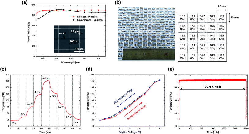
The optical transmittance spectra of the uniform Ni mesh- and commercial indium tin oxide (ITO) thin film-based transparent heaters are presented in Fig. 1(a). Here, the Ni mesh-based transparent heater exhibits an optical transmittance of 89.6% at 550 nm and an average transmittance of 86.8% over the entire visible range. These figures indicate that the prepared Ni mesh-based transparent heater has a higher optical transmittance than commercial ITO glass in the visible range except for the region from 480 nm to 575 nm. The inset in Fig. 1(a) shows an FE-SEM image of the transferred Ni micro-mesh pattern on the glass substrate, which has a width of 1.8 μm and a pitch of 100 μm. Fig. S1† presents a cross-sectional FE-SEM image of the Ni mesh structure with a thickness of 500 nm.Fig. 1(b) depicts the transferred Ni mesh structure on 100 × 100 mm2 glass and its sheet resistance uniformity. The sheet resistance standard deviation of 0.41 Ω sq−1 over 25 subsections suggests that it is suitable for transparent heaters with uniform electrical properties.
To assess the performance of the Ni mesh-based heater, we calculated the figure of merit (FoM) at the electrical to optical conductance ratio (σdc/σopt) as follows:9,19
 | (1) |
Fig. 1(c) shows the continuous heating performance of the Ni mesh-based transparent heater with increasing and decreasing input voltage. As the applied voltage increases from 0 V to 6 V in steps of 1.5 V, the steady-state temperature of the transparent heater significantly increases from room temperature (RT, 22.2–22.4 °C) to 178.4 °C. Inversely, the steady-state temperature drops to near RT as the applied voltage decreases to 0 V. Fig. 1(d) depicts the negligible hysteresis of the steady-state temperature as a function of input voltage.
The long-term operating performance of the transparent heater at DC 6 V is plotted in Fig. 1(e). Here, the steady-state temperature is maintained for 48 h.
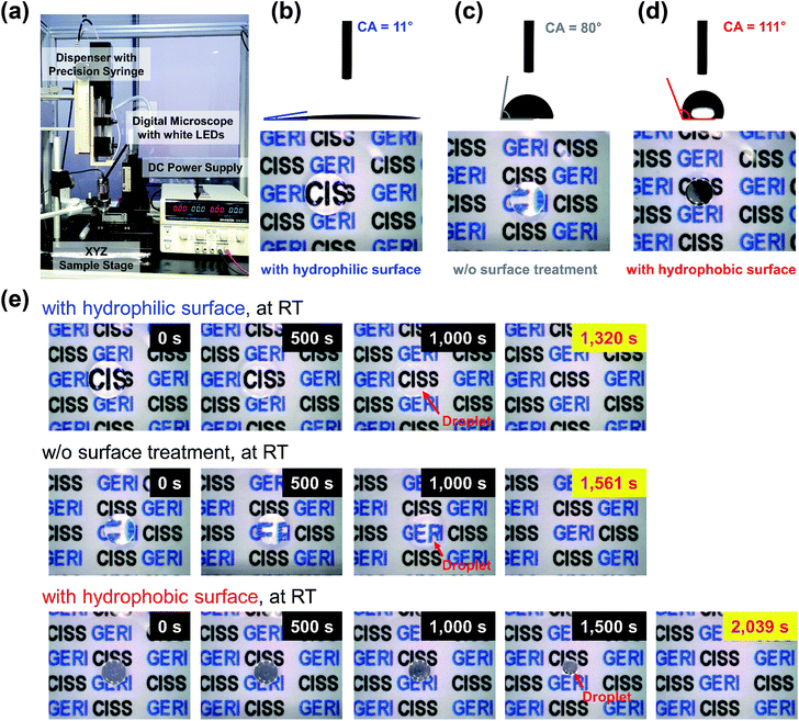
Droplet evaporation on the transparent heater surfaces was recorded by the digital microscope imaging system depicted in Fig. 2(a). Fig. 2(b)–(d) present the CA and microscopic images of water droplets on the Ni mesh-based transparent heater surfaces with and without treatment. The hydrophilic (CA = 11°) and hydrophobic (CA = 111°) properties of the heater surfaces shown in Fig. 2(b) and (d), respectively, were formed through O2 plasma treatment and the SAM method, respectively. In the three different cases, as the CA of the water droplet increases, the contact radius of the droplet to the heater surface decreases and its height increases.
Fig. 2(e) and S2† present the evaporation process and the complete evaporation times of water droplet on heater surfaces with different wetting properties and no heating. As shown in Fig. 2(e), the background images viewed through the droplets on the hydrophilic and normal surfaces are zoomed out during evaporation, indicating that the CA is decreasing while the contact line is fixed (constant contact line (CCL) mode). On the other hand, the background image viewed through the droplet on the hydrophobic surface does not change, and the droplet size gradually decreases as the droplet evaporates, which means that the CA stays fixed but the contact area moves (constant CA (CCA) mode). When a droplet evaporates on a substrate, a pinning phenomenon (CCL mode) is initially observed from the droplet on the surface. During evaporation, the pinning phenomenon becomes a depinning phenomenon (CCA mode) under the effect of a depinning force, and the depinning phenomenon is then replaced by a mixed phenomenon in which the contact line and angle decrease simultaneously just before complete evaporation.7,20,21 The total evaporation time of a droplet on a hydrophilic surface is usually shorter with a long pinning time (in CCL mode) due to the edge effect.22 Therefore, the time required for a water droplet to evaporate completely is about 1561 s when the surface is untreated. On the hydrophilic surface, the time required for complete evaporation is 1320 s shorter than that obtained with no surface treatment. The elapsed time is the longest for the hydrophobic surface, at 2039 s.
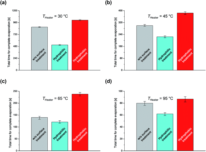
As an aside, we considered what would happen if the heater temperature was increased. Fig. 3 shows a plot of the times required for the complete evaporation of water droplets on heater surfaces with different wetting properties and heating temperatures (30 °C, 45 °C, 65 °C, and 95 °C). In addition, Fig. S3–S6† present microscopic images of the water droplet evaporation process. As shown in these figures, the complete evaporation time is greatly shortened as the heating temperature increases. In this case, the hydrophilic surface exhibits the shortest evaporation time, while the hydrophobic surface exhibits the longest evaporation time. In addition, we conducted the same experiment by placing a surface-treated Si substrate on a ceramic heater for comparison with a non-transparent heater (Table S1†). As a result, it was reconfirmed that the time required for complete water droplet evaporation changed in a similar way on transparent heaters. This phenomenon can be explained by two possible causes: (1) as the droplet contact diameter increases, the area for heat transfer from the heated solid surface to the liquid also increases, and (2) when the height-to-contact radius aspect ratio of the droplet decreases and the droplet layer becomes thinner as the CA decrease, the heat transfer to the liquid–vapor interface increases, resulting in an increase in evaporation rate due to the minimization of the temperature drop across the droplet.7,23 In addition, the evaporation time with a lower CA can be reduced by increasing the difference between the temperature of the heated substrate and ambient temperature,7,8 as shown in eqn (2).
 | (2) |
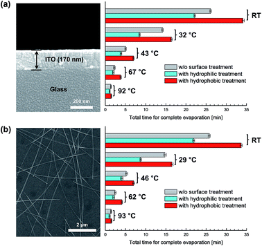
Finally, we replaced the Ni mesh-based transparent heater with ITO film and AgNWs. Fig. 4(a) and (b) show FE-SEM images of the ITO film and AgNW-based transparent heater and the total times required for the complete evaporation of water droplets from the transparent heaters with different wetting properties and heating temperatures. The result obtained in these two cases exhibit tendencies similar to the previous ones.
Conclusions
We determined that the evaporation characteristics of a droplet on the surface of a transparent heater depend on the surface wettability and that the evaporation rate can be controlled by modifying this surface wettability. Based on the experimental results, transparent heaters with controlled wettability are expected to be widely utilized as reference materials for defogging/deicing (or anti-fogging/anti-icing) devices or heating sources for automobiles, sensors, bio-chips, and greenhouses.Conflicts of interest
There are no conflicts to declare.Acknowledgements
This work was supported by the Center for Integrated Smart Sensors (CISS) funded by the Ministry of Science, ICT & Future Planning as Global Frontier Project (CISS-2011-0031870), the Ministry of Trade, Industry & Energy (MOTIE) and Korea Institute for Advancement of Technology (KIAT) part of the as Electronic Medical Equipment Part & Material Industrialization Foundation Construction Program (AA1229166), and a grant (The Core Project-02) from Gumi Core Components and Materials Technology Development Program of the Gumi Regional Government, 2017.References
- R. D. Deegan, O. Bakajin, T. F. Dupont, G. Huber, S. R. Nagel and T. A. Witten, Nature, 1997, 389, 827 CrossRef CAS.
- W. Wan, C. Wang, X. Lei, G. Zhou and H. Fang, Phys. Rev. Lett., 2015, 115, 195901 CrossRef PubMed.
- T. A. H. Nguyen, A. V. Nguyen, M. A. Hampton, Z. P. Xu, L. Huang and V. Rudolph, Chem. Eng. Sci., 2012, 69, 522 CrossRef CAS.
- C. Xie, G. Liu and M. Wang, Langmuir, 2016, 32, 8255 CrossRef CAS PubMed.
- N. D. Patil, P. G. Bange, R. Bhardwaj and A. Sharma, Langmuir, 2016, 32, 11958 CrossRef CAS PubMed.
- S. Wang, Y. Tu, R. Wan and H. Fang, J. Phys. Chem. B, 2012, 116, 13863 CrossRef CAS PubMed.
- S. Dash and S. V. Garimella, Phys. Rev. E, 2014, 89, 042402 CrossRef PubMed.
- S. Dash and S. V. Garimella, Langmuir, 2013, 29, 10785 CrossRef CAS PubMed.
- H.-J. Kim, Y. Kim, J.-H. Jeong, J.-H. Choi, J. Lee and D.-G. Choi, J. Mater. Chem. A, 2015, 3, 16621 CAS.
- P. Li, J. Ma, H. Xu, X. Xue and Y. Liu, J. Mater. Chem. C, 2016, 4, 3581 RSC.
- T. Y. Kim, Y. W. Kim, H. S. Lee, H. Kim, W. S. Yang and K. S. Suh, Adv. Funct. Mater., 2013, 23, 1250 CrossRef CAS.
- E.-H. Ko, H.-J. Kim, S.-J. Lee, J.-H. Lee and H. K. Kim, RSC Adv., 2016, 6, 46634 RSC.
- B. W. An, E.-J. Gwak, K. Kim, Y.-C. Kim, J. Jang, J.-Y. Kim and J.-U. Park, Nano Lett., 2016, 16, 471 CrossRef CAS PubMed.
- H.-J. Kim, S.-H. Lee, J. Lee, E.-S. Lee, J.-H. Choi, J.-H. Jung, J.-Y. Jung and D.-G. Choi, Small, 2014, 10, 3767 CrossRef CAS PubMed.
- M. A. Meitl, Z.-T. Zhu, V. Kumar, K. J. Lee, X. Feng, Y. Y. Huang, I. Adesida, R. G. Nuzzo and J. A. Rogers, Nat. Mater., 2006, 5, 33 CrossRef CAS.
- Y. Ahn, Y. Jeong and Y. Lee, ACS Appl. Mater. Interfaces, 2012, 4, 6410 CAS.
- K. S. Kumar, L. Jiang and C. A. Nijhuis, RSC Adv., 2017, 7, 14544 RSC.
- A. K. Gnanappa, C. O'Murchu, O. Slattery, F. Peters, T. O'Hara, B. Aszalós-Kiss and S. A. M. Tofail, J. Phys. Chem. C, 2008, 112, 14934 CAS.
- H.-J. Kim, D.-I. Kim, S.-S. Kim, Y.-Y. Kim, S.-E. Park, G. Choi, D. W. Lee and Y. Kim, AIP Adv., 2017, 7, 025112 CrossRef.
- X. Chen, R. Ma, J. Li, C. Hao, W. Guo, B. L. Luk, S. C. Li, S. Yao and Z. Wang, Phys. Rev. Lett., 2012, 109, 116101 CrossRef PubMed.
- W. Xu and C.-H. Choi, Phys. Rev. Lett., 2012, 109, 024504 CrossRef PubMed.
- D. H. Shin, S. H. Lee, J.-Y. Jung and J. Y. Yoo, Microelectron. Eng., 2009, 86, 1350 CrossRef CAS.
- J. Park, H.-S. Han, Y.-C. Kim, J.-P. Ahn, M.-R. Ok, K. E. Lee, J.-W. Lee, P.-R. Cha, H.-K. Seok and H. Jeon, Sci. Rep., 2015, 5, 18150 CrossRef CAS PubMed.
Footnotes |
| † Electronic supplementary information (ESI) available: Cross-sectional FE-SEM image of the Ni mesh structure on glass, complete evaporation times of water droplets on the surfaces of Ni mesh-based transparent heaters with different wetting properties at room temperature, evaporation process of water droplets on the surfaces of the Ni mesh-based transparent heaters with different wetting properties and heating temperatures (30 °C, 45 °C, 65 °C, and 95 °C), and total times for the complete water droplet evaporation on Si substrates with different wetting properties and heating temperatures. See DOI: 10.1039/c7ra08888d |
| ‡ Suhan Lee and Dong-Ik Kim contributed equally to this work. |
| This journal is © The Royal Society of Chemistry 2017 |


