 Open Access Article
Creative Commons Attribution 3.0 Unported Licence
In situ fabrication of porous MnCoxOy nanocubes on Ti mesh as high performance monolith de-NOx catalysts†
Jing Xu‡
,
Hongrui Li‡,
Yan Liu,
Lei Huang,
Jianping Zhang,
Liyi Shi and
Dengsong Zhang *
*
Research Center of Nano Science and Technology, School of Material Science and Engineering, Shanghai University, Shanghai 200444, China. E-mail: dszhang@shu.edu.cn; Fax: +86-21-66136079; Tel: +86-21-66137152
First published on 20th July 2017
Abstract
Herein, we have rationally designed and fabricated porous MnCoxOy nanocubes on a Ti mesh in situ, as a novel monolith de-NOx catalyst for selective catalytic reduction of NO by NH3 (NH3-SCR). The catalysts were systematically examined by X-ray diffraction, scanning electron microscopy, transmission electron microscopy, elemental mapping and catalytic performance tests. The results indicate that the surface of the titanium mesh is uniformly coated with a layer of cube-like arrays, and each cube is formed by the stacking of regular sheet layers. This structure could prevent the migration and agglomeration of metal oxides and enable the synergistic performance of the components during the catalytic reaction. In addition, due to the robust structure and morphology, the catalyst can sustain high NO conversion, while exhibiting superior catalytic cycle stability and good H2O resistance. Considering all these favorable properties, the developed material could serve as a promising candidate for monolith de-NOx catalysts; the in situ synthesis of hierarchical monolith catalysts also illustrates a new path for the development of environment-friendly and highly active monolith de-NOx catalysts.
Introduction
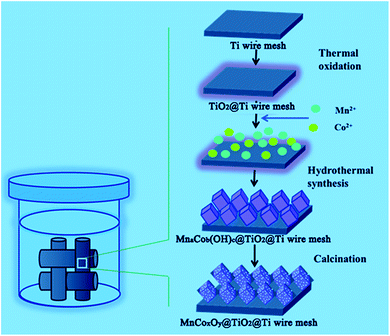
Nitrogen oxides (NOx) are one of the major air pollutants that can cause several ecological problems.1–3 The selective catalytic reduction of NO by NH3 (NH3-SCR) is one of the most efficient techniques for the control of NOx from stationary and mobile sources.4–9 Various catalysts that use this technique have been reported. Among them, V2O5–WO3 (MoO3)/TiO2 has been widely used commercially. However, there are some inevitable disadvantages during the application, such as the high working temperature, the high conversion of SO2 to SO3 and the toxicity of vanadium species to the environment and human health.10–14 Moreover, the SCR unit is installed upstream of the particle collector and desulfurizer in order to avoid reheating of the flue gas. Therefore, a highly active catalyst for low temperature SCR, which can be placed downstream of the electric precipitator and desulfurizer, is required.15,16It has been demonstrated that Mn-based metal oxides showed an excellent low temperature activity for the SCR reaction.17–23 Meng et al.24 found that the N2 selectivity of the Mn–Co mixed-oxide catalyst is higher than those of Co3O4 and MnOx in the temperature range from 50 °C to 375 °C due to the abundant surface acid sites, large active surface oxygen and good redox ability. Thirupathi et al.25 compared a series of Co/Mn atomic ratios and found that NO conversion and the broadening of the temperature window was greatly improved at Co/Mn = 0.4, due to the formation of a two-dimensional monolayer coverage. We26 developed a catalyst based on hollow porous MnxCo3−xO4 nanocages with excellent low-temperature SCR activity, high stability, and H2O and SO2 tolerance. This structure had a large surface area and more active sites to adsorb and activate the reaction gases. Moreover, the uniform distribution and strong interaction of manganese and cobalt oxide species strongly enhanced the catalytic cycle and inhibited the formation of manganese sulphate. However, the Mn–Co mixed-oxide catalyst was obtained only as particles. For industrial application, active catalysts are usually supported on monolithic honeycombs by wash-coating. The main drawbacks of these catalysts are nonuniform coating, weight loss, low inter-phase mass transfer rates and low mechanical strength.27–31 Metal substrates could be alternative choices due to their good thermal and mechanical properties, controllable mass transport, recyclability, and other advantages.32 Therefore, we have rationally designed and fabricated porous MnCoxOy nanocubes on Ti mesh in situ, as a novel monolith de-NOx catalyst for the NH3-SCR reaction of NO. The synthetic route is schematically illustrated in Scheme 1. TiO2 contributes a high surface area, high thermal stability and possesses profound surface acid–base properties to improve the resistance of SO2.33–37 Thus, TiO2 as a good carrier was obtained by the high temperature calcination of Ti mesh. Then, MnCoxOy precursor nanocube arrays are obtained by the urea assisted co-precipitation of Mn2+ and Co2+ nanoparticles on the surface of TiO2. Finally, the calcination procedure yields the MnCoxOy@TiO2@Ti wire mesh. In this design, the MnCoxOy nanocubes were anchored on the surface of the Ti wire mesh through TiO2. This structure could prevent the migration and agglomeration of the metal oxides and enable a synergistic performance between all the components during the catalytic reaction. The MnCoxOy@TiO2@Ti wire mesh catalyst can potentially serve as a high performance monolith de-NOx catalyst.
Experimental
Catalyst preparation
All reagents were of analytical grade, purchased from Sinopharm Chemical Reagent Co. Ltd (China) and used without further purification. The Ti wire mesh was purchased from Anping Kaian Metal Mesh Co. Ltd (Hebei, China). Before use, the Ti wire mesh was cut into pieces (3 cm × 11 cm, d = 0.8 cm) and pretreated with 4 M HNO3 aqueous solution at 60 °C for 4 h. Then, the Ti wire mesh was washed by isopropanol upon ultrasonication for 20 min, to remove the dirt and grease, and finally dried at 60 °C in the oven.In a typical synthesis, the Ti wire mesh was treated at 600 °C for 4 h with a ramping rate of 2 °C min−1 in air. A series of MnSO4·H2O, Co(NO3)2·6H2O and 24 mmol of urea were dissolved in 80 mL of deionized water under stirring for 1 h. Subsequently, the pretreated Ti wire mesh was immersed in the above-mentioned homogeneous solution and transferred to a 100 mL Teflon-lined stainless steel autoclave. The autoclave was heated and maintained at 90 °C for 24 h and then allowed to cool to room temperature naturally. The Ti wire mesh was washed by deionized water, dried overnight at 60 °C, and finally calcined in air at 600 °C for 4 h with a ramping rate of 1 °C min−1.
The MnCoxOy/TiO2/honeycomb ceramics and V–W/TiO2/honeycomb ceramics as reference samples were also fabricated via similar procedures. The preparation of the MnCoxOy/TiO2/honeycomb ceramics catalyst was carried out as follows. The commercial cordierite ceramic honeycomb (400 cells per square inch, 1 mm2 square channels and 100 μm a wall thickness) was purchased from the Yixing Weimin Ceramics Factory (China) and cut into a cylinder with a diameter of 2 cm and a height of 3 cm. The cordierite was pre-treated with ethanol and deionized water and dried at 70 °C overnight. According to the loadings of active component MnCo2O4 on TiO2 wire mesh (the mass difference before and after the reaction), 0.087 g of MnSO4·H2O and 0.302 g of Co(NO3)2·6H2O were dispersed in 10 mL deionized water under stirring for 20 min. Then, the pre-treated cordierite ceramic honeycomb was repeatedly immersed in the homogeneous solution and dried at 80 °C, until the active component entirely covered the cordierite. Finally, the products were calcined in air at 450 °C for 4 h at a ramping rate of 5 °C min−1.
The V–W/TiO2/honeycomb ceramics catalyst was obtained by a similar process as described above, except that the active component was obtained from 0.00257 g NH4VO3, 0.02187 g (NH4)10W12O41·xH2O and 0.178 g TiO2.
Characterization
The morphology and elemental information of the as-synthesized samples were monitored by a scanning electron microscope (SEM, JEOL JSM-6700F) equipped with an energy dispersive X-ray spectrometry (EDX) system. The samples were deposited on a sample holder with a piece of adhesive carbon tape and sputtered with a thin film of gold. Powder X-ray diffraction (XRD) patterns were recorded on a Rigaku D/MAX-RB X-ray diffractometer with Cu Kα (40 kV, 40 mA) radiation and a secondary beam graphite monochromator.Catalytic tests
The SCR experiments were carried out at atmospheric pressure in a fixed-bed stainless steel flow reactor (i.d. 1 cm). The temperature of the reactor was monitored and controlled by thermocouples that were inserted into the centre of the catalyst bed. The reactant gases were fed to the reactor by an electronic mass flow controller. The typical reactant gas composition was as follows: 500 ppm NO, 500 ppm NH3, 3 vol% O2 and N2 as balance. The NO-SCR experiments were performed over the catalysts from 100 to 470 °C and the gas hourly space velocity (GHSV) was 10![[thin space (1/6-em)]](https://www.rsc.org/images/entities/char_2009.gif) 000 h−1. The inlet and outlet concentrations of NO from the reactor were analyzed by a NO–NOx analyzer (KM9106). The concentrations of N2O and NH3 were measured by a transmitter IR N2O analyzer and IQ350 ammonia analyzer, respectively. All the stream lines were maintained at approximately 110 °C to prevent condensation of water and dissolution of NH3 in water. The NO conversion was calculated according to the following equation:
000 h−1. The inlet and outlet concentrations of NO from the reactor were analyzed by a NO–NOx analyzer (KM9106). The concentrations of N2O and NH3 were measured by a transmitter IR N2O analyzer and IQ350 ammonia analyzer, respectively. All the stream lines were maintained at approximately 110 °C to prevent condensation of water and dissolution of NH3 in water. The NO conversion was calculated according to the following equation:where [NO]in and [NO]out indicated the inlet and outlet concentrations at steady-state, respectively.
Results and discussion
Morphology and structure of the catalysts
The morphology and structure of the MnCoxOy@TiO2@Ti wire mesh were studied by SEM and TEM. Fig. 1 shows the SEM images of the MnCoxOy@TiO2@Ti wire mesh. Manganese and cobalt ions are deposited on the surface of the titanium mesh in situ by a hydrothermal reaction to form precursor salts and yield a uniform coating of the manganese and cobalt composite oxide layer upon calcination. The active component oxides closely combined with the metal wire mesh carrier are beneficial for the effective mass transfer and heat transfer in the process of denitrification, which can avoid the effect of catalyst sintering.34,38 The surface of the titanium mesh is uniformly coated with a layer of a cube arrays, and each cube is formed by the stacking of regular sheet layers (Fig. 1b and c). The cube layer is composed of uniform particles (Fig. 1d), which is due to the decomposition of cubic precursor salts. Several inorganic species (H2O, NO2, SO2, etc.) volatilize by decomposition and diffuse to form the ordered pores. The cubes could not be obtained without the Ti wire mesh (Fig. S1†). The three-dimensional hierarchical structure not only has a larger effective specific surface area, which helps to expose more reactive sites and adsorb more reactive gas molecules, but also avoids the sintering of the active component at high temperature. The manganese cobalt compound oxides can play a synergistic catalytic role on the improved performance of the monolith catalysts.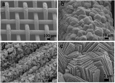 | ||
| Fig. 1 SEM images of the MnCoxOy@TiO2@Ti wire mesh. (a) Overview; (b) surface morphology of wires; (c) morphology of cubic layers; and (d) microstructure of cubic layers. | ||
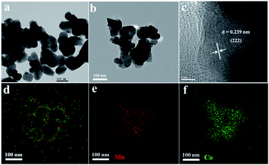
Fig. 2 shows the TEM images of MnCoxOy (the active components were scraped off from the titanium mesh surface). The obtained MnCoxOy nanoparticles are uniform with an average size of 80–120 nm (Fig. 2a and b). The HRTEM image of MnCoxOy (Fig. 2c) showed lattice fringes in the (222) direction with an interplanar spacing of 0.239 nm. In order to understand the surface elemental distribution of MnCoxOy@TiO2@Ti, the EDX-mapping is shown in Fig. 2d–f. The Mn and Co elements show a highly uniform distribution in the MnCoxOy nanoparticles, indicating that the Mn and Co atoms are arranged in the cube-like structure and have a strong interaction between them.26 This structure ensures the uniform dispersion of the active components to improve the catalytic activity.
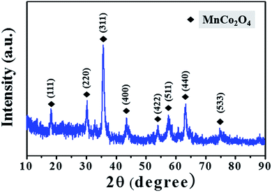
The XRD patterns of the MnCoxOy powders scraped from the Ti wire mesh also confirm the formation of MnCoxOy (Fig. 3); the peaks at 18.55°, 30.54°, 35.99°, 43.76°, 54.34°, 57.91°, 63.62° and 76.35° indicate that the nanocrystals of MnCo2O4 possess the spinel structure (JCPDS 23-1237). The diffraction peaks are narrow and strong, which means that the MnCo2O4 has small particle size and regular morphology. This is also consistent with the results of SEM and TEM.
The chemical states on the catalyst surface were investigated by XPS measurements. The catalyst shows two overlapping peaks of the O 1s (Fig. S2a†); the low binding energy peak (531.8 eV) was assigned to lattice oxygen, and the high binding energy peak (533.0 eV) was attributed to chemisorbed oxygen, which could originate from defect oxides or hydroxyl-like groups. The surface chemisorbed oxygen has been reported as the most active oxygen, particularly in the oxidation reaction due to its higher mobility. The abundance of chemisorbed oxygen in MnCoxOy@TiO2@Ti wire mesh may enhance the NH3-SCR reaction by participating in the “fast SCR” reaction route.
The Co 2p3/2 spectrum of the catalyst is fitted into two peaks assigned to Co3+ (779.9 eV) and Co2+ (781.5 eV) (Fig. S2b†). The Co3+ species is preferred for the oxidation cycle among the various valence states of cobalt, resulting in an enhancement of NH3 chemisorption. Thus, the Co3+ species could enhance the catalytic activity.
The Mn 2p3/2 spectra can be divided into three characteristic peaks attributed to Mn2+ (640.6 eV), Mn3+ (642.0 eV), and Mn4+ (644.1 eV) (Fig. S2c†). The Mn4+ species and its redox cycle might contribute to the high activity in the NH3-SCR reaction at low temperatures and enhance oxidation of NO to NO2.
The H2-TPR analysis was employed to evaluate the reducibility of the catalyst. The TPR profiles of the MnCoxOy@TiO2@Ti wire mesh are shown in Fig. S3.† As can be seen, the catalyst shows three distinct peaks at 306, 406, and 457 °C. The low temperature peak at 306 °C corresponds to the reduction of the manganese species. The later peaks at 406 and 457 °C are attributed to the Co3+ to Co2+ and Co2+ to Co0 transitions, respectively.
The NH3-TPD experiments were performed to investigate the adsorption and activation of NH3 on the surface acid sites of the catalyst, which is generally viewed as the key process in the NH3-SCR of NO. In the NH3-TPD profile (Fig. S4†), the low temperature desorption peaks between 100 and 300 °C belong to the ammonia desorbed from weak Lewis or Brønsted acid sites and the high temperature desorption peaks between 300 and 600 °C belong to the ammonia desorbed from strong acid sites.3 Therefore, the NH3-TPD measurement was performed as shown in Fig. S4.† The catalyst exhibits two desorption peaks: the weak peak centred at 190 °C attributed to ammonia desorbed from the weak acid sites, and the strong peak observed at 484 °C assigned to ammonia desorbed from the strong acid sites on the catalyst. This reveals a much larger area, indicating the presence of several acid sites.
Catalytic performance
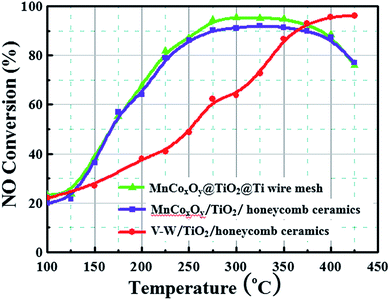
The NH3-SCR activity of MnCoxOy@TiO2@Ti wire mesh is shown in Fig. 4. For comparison, manganese salt, cobalt salt and TiO2 were impregnated on the conventional honeycomb ceramics and the V–W/TiO2/honeycomb ceramics catalyst was also prepared. The MnCoxOy@TiO2@Ti wire mesh and MnCoxOy/TiO2/honeycomb ceramics show a similar NO conversion, implying that the Mn and Co mixed oxides are the active components. In the range of 200–425 °C, the MnCoxOy@TiO2@Ti wire mesh shows a better NO conversion than the MnCoxOy/TiO2/honeycomb ceramics. Particularly, at 275–350 °C, the maximum NO conversion of the MnCoxOy@TiO2@Ti wire mesh is 95%, and 92% for the MnCoxOy/TiO2/honeycomb ceramics. During the five recyclable catalytic tests, the maximum NO conversion remains at 95% (Fig. S5†). The three-dimensional titanium wire mesh support is more favourable for improved denitrification performance compared to traditional ceramic honeycomb carriers due to its good mechanical properties and heat transfer performance. This can also avoid the sintering of the active component of the catalyst at high temperature and influence the catalytic performance. Additionally, the metal wire mesh are easier to recycle as compared to the ceramic. From Fig. 4, the V–W/TiO2/honeycomb ceramics show a maximum NO conversion of 97% at 400 °C. Thus, the MnCoxOy@TiO2@Ti wire mesh and MnCoxOy/TiO2/honeycomb ceramics display denitrification activity at lower temperatures than the V–W/TiO2/honeycomb ceramics, which further confirms that these catalysts with the active components of cobalt manganese composite oxides are conducive to practical application. Therefore, the titanium wire mesh is demonstrated as an excellent catalyst substrate for the removal of NOx, which is expected to replace the traditional honeycomb ceramic carrier. In addition, it can be recycled to avoid environmental pollution and wastage of resources. A comparison of the MnCoxOy@TiO2@Ti wire mesh with other high-activity Mn-based catalysts that were reported in the literature has been summarized in Table S1.† Thus, Mn or Mn–Co is a good de-NOx catalyst, but those are powders rather than monolith.A relative turnover frequency (TOF) value was employed to calculate the activities of the catalyst. The relative TOF (s−1) of NO over each Mn atom was calculated by the following equation:
In order to have a better understanding of the improved morphology and catalytic ability of the MnCoxOy@TiO2@Ti wire mesh, different conditions were investigated. With a change in solution concentration, the obtained morphology is different (Fig. S6†). When the molar amount of Mn is 4 mmol, the highest loading of the surface active component on the titanium wire mesh is observed, the layered cubic structure is the most regular and displays the most exposed surface, which enables adsorption and activation of the gas molecules in the process of denitrification and improves the catalyst activity. With the increase of duration of the hydrothermal reaction, the active load gradually increased and an even load was obtained on the surface (Fig. S7†). The saturated load was achieved at 12 h and did not display a significant change upon further increase of the duration.
There is a close relationship between the activity of the monolith catalyst and the proportion of the components. Different proportions of the monolith catalyst may have different crystal structures, specific surface areas and redox properties, which ultimately lead to different catalyst activities.39–47 When the concentration of MnSO4·H2O was 4 mmol and Co (NO3)2·6H2O was 8 mmol, the monolith catalyst exhibited the best catalytic activity in the entire temperature range, compared to the other catalysts (Fig. S8†). In the temperature range 275–400 °C, the NO conversion rate is more than 87% and reached a maximum value of 96% at 325 °C.
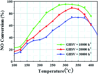
The NO conversion under different GHSVs is very crucial for practical applications.6,28 Fig. 5 shows the NO conversion of MnCo2O4 under different space velocities. At 10![[thin space (1/6-em)]](https://www.rsc.org/images/entities/char_2009.gif) 000 h−1, the catalyst displayed the best performance. In the range 200–400 °C, the NO conversion was >70%, while it was >94% at 275–350 °C. At 20
000 h−1, the catalyst displayed the best performance. In the range 200–400 °C, the NO conversion was >70%, while it was >94% at 275–350 °C. At 20![[thin space (1/6-em)]](https://www.rsc.org/images/entities/char_2009.gif) 000 h−1, the NO conversion was 90% at 325 °C and reduced at all other temperatures. The entire catalytic activity window became narrow. At 30
000 h−1, the NO conversion was 90% at 325 °C and reduced at all other temperatures. The entire catalytic activity window became narrow. At 30![[thin space (1/6-em)]](https://www.rsc.org/images/entities/char_2009.gif) 000 h−1, the catalytic activity decreased significantly and the maximum conversion rate of NO was 74%. The entire active range window shifted to the high temperature zone. The results show that the denitrification activity of the MnCoxOy@TiO2@Ti wire mesh decreased gradually with the increase in space velocity. From the actual operating temperature range and the maximum NO conversion requirements, the appropriate gas flow rate or amount of catalyst to achieve the corresponding space velocity condition can be selected.
000 h−1, the catalytic activity decreased significantly and the maximum conversion rate of NO was 74%. The entire active range window shifted to the high temperature zone. The results show that the denitrification activity of the MnCoxOy@TiO2@Ti wire mesh decreased gradually with the increase in space velocity. From the actual operating temperature range and the maximum NO conversion requirements, the appropriate gas flow rate or amount of catalyst to achieve the corresponding space velocity condition can be selected.
The catalytic stability is quite important in practical applications for the catalyst. Fig. 6 shows the stability test curve of the MnCoxOy@TiO2@Ti wire mesh at 325 °C. In the first 2 h, NO conversion significantly decreased from 98% to 95% and slowly reduced further to 92% after a long test of 13 h. Thus, the NO conversion was maintained at >90% during the entire test. This shows that the MnCoxOy@TiO2@Ti wire mesh can not only provide high NH3-SCR activity in a wide range of operating temperatures, but can also maintain a high NO conversion rate under longer test conditions. This also proves that the mechanical stability and the three dimensional structure of the catalyst support titanium mesh enables a good mass transfer and heat transfer performance to avoid the sintering of the catalyst in the long term test. The stability of the MnCoxOy/TiO2/honeycomb and V–W/TiO2/honey-comb ceramics was also tested (Fig. S9†). The result of MnCoxOy/TiO2/honeycomb ceramics is similar to that of the MnCoxOy@TiO2@Ti wire mesh, but the NO conversion is lower due to the aggregation of nanoparticles and poor transformation. The NO conversion of V–W/TiO2/honeycomb ceramics is relatively low and descends rapidly.
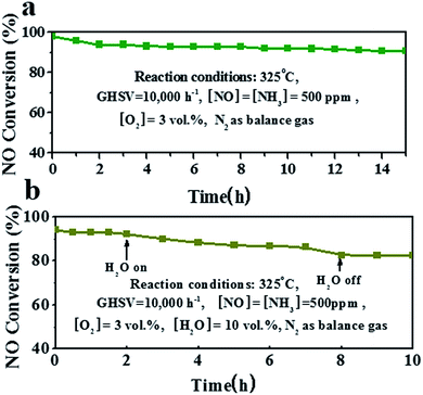 | ||
| Fig. 6 (a) Stability test at 325 °C for 15 h and (b) H2O durability test of the MnCoxOy@TiO2@Ti wire mesh at 325 °C. | ||
Some residual H2O always exists in the exhaust fume, which can deactivate the catalyst if adsorbed on the active sites.39–42 The test curve of the MnCoxOy@TiO2@Ti wire mesh in the presence of 10 vol% water vapor at 325 °C is shown in Fig. 6a. The NO conversion of the catalyst was about 93% in the absence of steam. After the introduction of 10 vol% H2O, the conversion rate slowed to 89% during the 6 h test. This is because the water vapor and NH3 molecules on the surface of the catalyst compete for adsorption sites to inhibit the adsorption and activation of reactive gas molecules. However, after removing H2O, the conversion of NO remained unchanged. The NO conversion of the catalyst was >90% during the entire process of water resistance testing, which shows that the catalyst has better ability to resist H2O steam toxicity. The performance of H2O resistance at 275 °C is similar (Fig. S10†). After the introduction of 10 vol% H2O, the conversion rate slows to 80% during the 6 h test.
Conclusions
In summary, we have rationally designed and fabricated porous MnCoxOy nanocubes on Ti mesh in situ as a novel monolith de-NOx catalyst for NH3-SCR of NO. The MnCoxOy@TiO2@Ti wire mesh catalyst displays an enhanced NH3-SCR activity compared to the honeycomb ceramics based monolith catalysts, with a maximum NO conversion of 95% at 275 °C. The NO conversion is maintained >90% at a GHSV of 10![[thin space (1/6-em)]](https://www.rsc.org/images/entities/char_2009.gif) 000 h−1 within the broad temperature window from 275 °C to 400 °C. The surface of the titanium mesh is uniformly coated with a layer of cube-like arrays, and each cube is formed by the stacking of regular sheet layers. This structure could prevent the migration and agglomeration of metal oxides and provide a synergistic performance between the components during the catalytic reaction. The catalyst can sustain high NO conversion and exhibits superior catalytic cycle stability and good H2O resistance. The in situ growth of composite metal oxides on the wire mesh can not only reduce environmental pollution due to the binder in the traditional monolithic catalyst, but also can be easily recovered twice. The wire mesh has good mechanical and mass transfer properties, which benefits the denitrification reaction. The idea and the concept of the preparation of the novel monolithic de-NOx catalyst are of great significance for the development and design of new monolithic catalysts.
000 h−1 within the broad temperature window from 275 °C to 400 °C. The surface of the titanium mesh is uniformly coated with a layer of cube-like arrays, and each cube is formed by the stacking of regular sheet layers. This structure could prevent the migration and agglomeration of metal oxides and provide a synergistic performance between the components during the catalytic reaction. The catalyst can sustain high NO conversion and exhibits superior catalytic cycle stability and good H2O resistance. The in situ growth of composite metal oxides on the wire mesh can not only reduce environmental pollution due to the binder in the traditional monolithic catalyst, but also can be easily recovered twice. The wire mesh has good mechanical and mass transfer properties, which benefits the denitrification reaction. The idea and the concept of the preparation of the novel monolithic de-NOx catalyst are of great significance for the development and design of new monolithic catalysts.
Acknowledgements
The authors acknowledge the support of the National Natural Science Foundation of China (U1462110).Notes and references
- M. F. Fu, C. T. Li, P. Lu, L. Qu, M. Y. Zhang, Y. Zhou, M. G. Yu and Y. Fang, Catal. Sci. Technol., 2014, 4, 14–25 CAS.
- P. Zhang and D. Y. Li, Catal. Lett., 2014, 144, 959–963 CrossRef CAS.
- T. Zhang, J. Liu, D. Wang, Z. Zhao, Y. Wei, K. Cheng, G. Jiang and A. Duan, Appl. Catal., B, 2014, 148, 520–531 CrossRef.
- S. J. Yang, F. H. Qi, Y. Liao, S. C. Xiong, Y. Lan, Y. W. Fu, W. P. Shan and J. H. Li, Ind. Eng. Chem. Res., 2014, 53, 5810–5819 CrossRef CAS.
- L. J. Xie, F. D. Liu, L. M. Ren, X. Y. Shi, F. S. Xiao and H. He, Environ. Sci. Technol., 2014, 48, 566–572 CrossRef CAS PubMed.
- Y. Shu, T. Aikebaier, X. Quan, S. Chen and H. T. Yu, Appl. Catal., B, 2014, 150, 630–635 CrossRef.
- M. S. Maqbool, A. K. Pullur and H. P. Ha, Appl. Catal., B, 2014, 152, 28–37 CrossRef.
- R. B. Jin, Y. Liu, Y. Wang, W. L. Cen, Z. B. Wu, H. Q. Wang and X. L. Weng, Appl. Catal., B, 2014, 148, 582–588 CrossRef.
- R. Camposeco, S. Castillo, V. Mugica, I. Mejia-Centeno and J. Marin, Catal. Commun., 2014, 45, 54–58 CrossRef CAS.
- S. J. Yang, C. Z. Wang, L. Ma, Y. Peng, Z. Qu, N. Q. Yan, J. H. Chen, H. Z. Chang and J. H. Li, Catal. Sci. Technol., 2013, 3, 161–168 CAS.
- I. Nova, L. Lietti, L. Casagrande, L. Dall'Acqua, E. Giamello and P. Forzatti, Appl. Catal., B, 1998, 17, 245–258 CrossRef CAS.
- W. Q. Xu, H. He and Y. B. Yu, J. Phys. Chem. C, 2009, 113, 4426–4432 CAS.
- L. Chen, Z. Si, X. Wu and D. Weng, ACS Appl. Mater. Interfaces, 2014, 6, 8134–8145 CAS.
- Y. Peng, C. X. Liu, X. Y. Zhang and J. H. Li, Appl. Catal., B, 2013, 140, 276–282 CrossRef.
- S. L. Zhang, X. X. Liu, Q. Zhong and Y. Yao, Catal. Commun., 2012, 25, 7–11 CrossRef CAS.
- Y. J. Kim, H. J. Kwon, I. S. Nam, J. W. Choung, J. K. Kil, H. J. Kim, M. S. Cha and G. K. Yeo, Catal. Today, 2010, 151, 244–250 CrossRef CAS.
- Q. Q. Tian, H. F. Liu, W. Y. Yao, Y. Wang, Y. Liu, Z. B. Wu, H. Q. Wang and X. L. Weng, J. Nanomater., 2014, 4, 1–6 Search PubMed.
- K. H. Park, S. M. Lee, S. S. Kim, D. W. Kwon and S. C. Hong, Catal. Lett., 2013, 143, 246–253 CrossRef CAS.
- S. J. Yang, Y. W. Fu, Y. Liao, S. C. Xiong, Z. Qu, N. Q. Yan and J. H. Li, Catal. Sci. Technol., 2014, 4, 224–232 CAS.
- C. Tang, H. Zhang and L. Dong, Catal. Sci. Technol., 2016, 6, 1248–1264 CAS.
- S. Wu, X. Yao, L. Zhang, Y. Cao, W. Zou, L. Li, K. Ma, C. Tang, F. Gao and L. Dong, Chem. Commun., 2015, 51, 3470–3473 RSC.
- K. Ma, W. Zou, L. Zhang, L. Li, S. Yu, C. Tang, F. Gao and L. Dong, RSC Adv., 2017, 7, 5989–5999 RSC.
- R.-t. Guo, M.-y. Li, P. Sun, S.-m. Liu, S.-x. Wang, W.-g. Pan, S.-w. Liu, J. Liu and X. Sun, RSC Adv., 2017, 7, 19912–19923 RSC.
- B. Meng, Z. B. Zhao, Y. S. Chen, X. Z. Wang, Y. Li and J. S. Qiu, Chem. Commun., 2014, 50, 12396–12399 RSC.
- B. Thirupathi and P. G. Smirniotis, Appl. Catal., B, 2011, 110, 195–206 CrossRef CAS.
- L. Zhang, L. Shi, L. Huang, J. Zhang, R. Gao and D. Zhang, ACS Catal., 2014, 4, 1753–1763 CrossRef CAS.
- Y. Shu, T. Aikebaier, X. Quan, S. Chen and H. Yu, Appl. Catal., B, 2014, 150, 630–635 CrossRef.
- J. Yao, J. S. Choi, K. S. Yang, D. Z. Sun and J. S. Chung, Korean J. Chem. Eng., 2006, 23, 888–895 CrossRef CAS.
- S. Cai, D. Zhang, L. Shi, J. Xu, L. Zhang, L. Huang, H. Li and J. Zhang, Nanoscale, 2014, 6, 7346–7353 RSC.
- L. del Rio and G. Marban, Appl. Catal., B, 2012, 126, 39–46 CrossRef CAS.
- Z. G. Lei, C. P. Wen, J. Zhang and B. H. Chen, Ind. Eng. Chem. Res., 2011, 50, 5942–5951 CrossRef CAS.
- S. Cai, J. Liu, K. Zha, H. Li, L. Shi and D. Zhang, Nanoscale, 2017, 9, 5648–5657 RSC.
- Q. J. Jin, Y. S. Shen and S. M. Zhu, J. Colloid Interface Sci., 2017, 487, 401–409 CrossRef CAS PubMed.
- Y. Y. He, M. E. Ford, M. H. Zhu, Q. C. Liu, U. Tumuluri, Z. L. Wu and I. E. Wachs, Appl. Catal., B, 2016, 193, 141–150 CrossRef CAS.
- X. S. Du, X. M. Wang, Y. R. Chen, X. Gao and L. Zhang, J. Ind. Eng. Chem., 2016, 36, 271–278 CrossRef CAS.
- F. Giraud, C. Geantet, N. Guilhaume, S. Loridant, S. Gros, L. Porcheron, M. Kanniche and D. Bianchi, J. Phys. Chem. C, 2015, 119, 15401–15413 CAS.
- J. Liu, X. Li, Q. Zhao, J. Ke, H. Xiao, X. Lv, S. Liu, M. Tadé and S. Wang, Appl. Catal., B, 2017, 200, 297–308 CrossRef CAS.
- H. Li, D. Zhang, P. Maitarad, L. Shi, R. Gao, J. Zhang and W. Cao, Chem. Commun., 2012, 48, 10645–10647 RSC.
- C. Fang, D. Zhang, L. Shi, R. Gao, H. Li, L. Ye and J. Zhang, Catal. Sci. Technol., 2013, 3, 803–811 CAS.
- C. Fang, D. Zhang, S. Cai, L. Zhang, L. Huang, H. Li, P. Maitarad, L. Shi, R. Gao and J. Zhang, Nanoscale, 2013, 5, 9199–9207 RSC.
- S. Cai, D. Zhang, L. Zhang, L. Huang, H. Li, R. Gao, L. Shi and J. Zhang, Catal. Sci. Technol., 2014, 4, 93–101 CAS.
- L. Zhang, D. S. Zhang, J. P. Zhang, S. X. Cai, C. Fang, L. Huang, H. R. Li, R. H. Gao and L. Y. Shi, Nanoscale, 2013, 5, 9821–9829 RSC.
- L. Ma, J. H. Li, R. Ke and L. X. Fu, J. Phys. Chem. C, 2011, 115, 7603–7612 CAS.
- X. A. Gao, X. S. Du, L. W. Cui, Y. C. Fu, Z. Y. Luo and K. F. Cen, Catal. Commun., 2010, 12, 255–258 CrossRef CAS.
- M. Casapu, O. Krocher, M. Mehring, M. Nachtegaal, C. Borca, M. Harfouche and D. Grolimund, J. Phys. Chem. C, 2010, 114, 9791–9801 CAS.
- M. Kang, E. D. Park, J. M. Kim and J. E. Yie, Catal. Today, 2006, 111, 236–241 CrossRef CAS.
- Y. Shu, H. Sun, X. Quan and S. Chen, J. Phys. Chem. C, 2012, 116, 25319–25327 CAS.
Footnotes |
| † Electronic supplementary information (ESI) available: SEM images of MnCoxOy@TiO2@Ti wire mesh prepared with different precursor concentrations; SEM images of MnCoxOy@TiO2@Ti wire mesh prepared with different reaction times; effect of NH3-SCR properties of wire mesh MnCoxOy@TiO2@Ti with different quantities of Mn and Co. See DOI: 10.1039/c7ra03182c |
| ‡ These authors contributed equally to this work. |
| This journal is © The Royal Society of Chemistry 2017 |

