 Open Access Article
Creative Commons Attribution 3.0 Unported Licence
Investigation into the structural features and microwave absorption of doped barium hexaferrites
S. V.
Trukhanov
 *abc,
A. V.
Trukhanov
abc,
V. G.
Kostishyn
a,
L. V.
Panina
a,
An. V.
Trukhanov
ac,
V. A.
Turchenko
def,
D. I.
Tishkevich
c,
E. L.
Trukhanova
ac,
O. S.
Yakovenko
g and
L. Yu.
Matzui
g
aNational University of Science and Technology “MISiS”, Leninskii av., 4, Moscow, 119049 Russia. E-mail: truhanov@ifttp.bas-net.by
bLaboratory of single crystal growth, South Ural State University, Lenin av., 76, Chelyabinsk, 454080, Russia
cScientific Practical Materials Research Centre, National Academy of Sciences of Belarus, P. Brovki str., 19, Minsk, 220072 Belarus, Russia
dFrank Laboratory of Neutron Physics, Joint Institute for Nuclear Research, Dubna, Moscow region, 141980 Russia
eDonetsk Institute for Physics and Engineering, National Academy of Sciences of Ukraine, R. Luxembourg str., 72, Donetsk, 83114 Ukraine
fDonetsk Institute of Physics and Technology named after O.O. Galkin of the NAS of Ukraine, Prospect Nauky, 46, Kyiv, 03680, Ukraine
gKiev National University named after Taras Shevchenko, Vladimirskaya str., 64/13, Kiev, 01601 Ukraine
First published on 27th June 2017
Abstract
BaFe12−xGaxO19 (x ≤ 1.2) hexaferrites were synthesized via the usual ceramic technology. It has been established that with an increase in x, the unit cell and magnetic parameters monotonically decrease. The frequency of natural ferromagnetic resonance firstly decreases from 49.6 GHz down to 49.1 GHz when x = 0.6, and then it increases up to 50.5 GHz. The line width monotonically increases from 3.5 GHz up to 5 GHz. The peak amplitude of the resonant curve changes slightly with the exception of when x = 0.9, when it reaches −16 dB. The 1.3 GHz kOe−1 frequency shift in the bias field is more intensive for small values, when x = 0.3. The decreasing values of the magnetic parameters are a result of the dilution of Fe3+–O2−–Fe3+ superexchange interactions. The behavior of the amplitude-frequency characteristics is largely determined through the reduction of uniaxial exchange anisotropy. The prospects of Ga-substituted hexaferrites acting as a material that effectively absorbs the high-frequency electromagnetic radiation are shown.
1. Introduction
M-type hexagonal ferrites continue to attract the attention of researchers.1 The problems caused by electromagnetic interference for high-frequency electronic devices working in the gigahertz range have lately received increasing attention. Among various microwave absorbing materials, barium and strontium ferrites with M-type hexagonal structures have been proved to be the most functional materials, due to the simultaneous presence of dielectric and magnetic losses.2 These compounds are characterized by the coexistence of strong intrasublattice Heisenberg exchange interactions and weak competing intersublattice exchange interactions. The intrasublattice interactions appear to dominate and help form a ferrimagnetic structure with large magnetic parameters. Strong competing intersublattice exchange interactions can lead to non-collinear magnetic structures with small magnetic parameters, such as the saturation magnetic moment and coercitivity.3Interest in the M-type BaFe12O19 barium ferrite with a hexagonal structure and its solid solutions substituted with different diamagnetic cations (Al3+, In3+, Ga3+, Sc3+, etc.)4–6 is explained also by their good functional properties.7 Their excellent chemical stability and corrosion resistance8 make them ecologically safe and suitable for applications, practically without time restrictions. The combination of high coercive force (Hc ∼ 160–55 kA m−1) with rather high residual induction allows them to be used as permanent magnets with satisfactory specific magnetic energy.9 Their low conductivity (ρ ∼ 108 Ω cm) allows the application of hexaferrite magnets in the presence of high-frequency magnetic fields. For the first time, barium hexaferrite, isomorphic to PbO·6Fe2O3 magnetoplumbite, was used by the Philips firm,10 still in the 1950s. The main magnetic, electric and structural properties of hexaferrites are discussed in the review in ref. 11.
Until now barium hexaferrite was widely used only in permanent magnets,12 high-frequency absorbers13,14 and high density magnetic storage with perpendicular magnetization.15 Recently, the significant growth in publications on M-type barium hexaferrites caused by the coexistence of ferrimagnetic and ferroelectric ordering at room temperature16–21 is also noted. M-type barium hexaferrites have prospective use for the absorption of electromagnetic radiation (EMR) in the microwave range, considering their magnetic properties and the possibilities of their modification through various substitutions, including with nanoparticles. There are works on the effective absorption of EMR using this material in the decimeter and centimeter spectral range22 that show the electromagnetic compatibility of microelectronics and radio equipment devices.
The high values of the magnetocrystalline anisotropy and the ferrimagnetic–paramagnetic phase transition temperature are the main advantages of M-type barium hexaferrites. Collinear ferrimagnetic ordering with a Curie temperature of ∼740 K is formed in M-type barium hexaferrite. The change in the magnetic bond number of Fe3+ cations in the multicomponent oxidic system caused by the introduction into the crystal structure of diamagnetic cations23 or by the creation of a deviation from stoichiometry on oxygen24 allows the operation of its functional properties.
An analysis of M-type barium hexaferrite properties in the microwave range shows that the working range – the range of effective EMR absorption – lies in the centimeter spectral range.25 The application of substituted M-type barium hexaferrites with a large constant of magnetocrystalline anisotropy as fillers in composite materials allows for the frequency selective absorption of EMR, using the controlled resonances of domain boundaries and the rotation of magnetization (natural ferromagnetic resonance, NFR). It is known that the absorption peak of BaFe12O19 M-type barium hexaferrite lies in the range of ∼47–50 GHz,26 whereas the substitution of the iron cations with Mn2+, Co2+ and Ti4+ cations reduces the absorption maximum down to 13.4 GHz.5 It is considered that losses at high frequencies are generally caused by NFR. It is possible to displace the absorption peak and to expand the absorption strip in the microwave range through control at the diamagnetic substitution level.
Ferrimagnetic resonance measurements were made at room temperature on polished spheres of about 0.3 mm size for Al, Ga and Sc substituted BaFe12O19 hexaferrites at frequencies between 3 GHz and 90 GHz.27 From these measurements, the values of the anisotropy field from nearly zero up to 29 kOe were found for Sc-substitution levels x ≤ 1.65 and for Al levels x ≤ 2, respectively. The observed FMR linewidth ΔH can be described from a frequency independent two-magnon scattering contribution ranging between 5 Oe and 10 Oe, being, for the substitutions studied, proportional to the reciprocal of the Curie temperature. A relation predicting the dependence of ΔH on frequency and substitution level is proposed.
In this paper, the absorption parameters for weakly substituted barium hexaferrites are investigated. The results of this work can find application in ensuring intrasystem and intersystem electromagnetic compatibility and also in ensuring the operational reliability of devices and equipment under conditions of increased levels of microwave influence, due to the selective absorption of EMR over the set range of frequencies.
2. Experimental technique
BaFe12−xGaxO19 (0 <x ≤ 1.2) polycrystalline samples were obtained from Fe2O3 and Ga2O3 oxides and BaCO3 carbonate, taken in corresponding proportions.28 The initial compositions were exposed to firing in air at 1200 °C (6 h), and were then sintered at 1300 °C (6 h). After sintering, the samples were slowly cooled (∼100 °C h−1).The crystal structures of the obtained samples were investigated using X-ray diffraction, which was carried out on a powder D8 Advance diffractometer (Bruker) with the following parameters: 40 kV, 40 mA, Cu-Kα radiation (λ = 1.5406 Å). For the XRD measurements, the Δ2θ step size is 0.03° and the integration time is ∼10 s. The refinement of the X-ray diffraction data was carried out using Rietveld full profile analysis,29 by means of the FullProf30 program.
In the present paper, the oxygen content and temperature stability of the oxygen sublattice were investigated using thermogravimetric analysis (TGA).31 There is a lack of information about the oxygen content of ferrites, especially hexaferrites. It is generally accepted that for any interpretation of the properties of magnetic oxides, knowledge of the oxygen stoichiometry is critical.32 TGA studies have shown that the relative error in the oxygen content of the investigated hexaferrites is less than 0.6% mol. Their oxygen content may be written as “O18.9±0.1” for all substitution concentrations.33 The oxygen content remains stable up to 1000 °C. It has been shown in many papers that the magnetic behavior in oxygen deficient oxides changes dramatically with anionic deficiency.34
The DC-susceptibility and specific magnetization were investigated using a universal cryogenic high-field measuring system (Liquid Helium Free High Field Measuring System, Cryogenic Ltd, London, UK) at a temperature of 300 K in external magnetic fields up to 2 T (field curves) and in a low field of 0.01 T over the temperature range of 4–750 K (temperature curves).35 The magnetic measurements were made using polycrystalline samples with average sizes of 2 × 3 × 5 mm3. The spontaneous magnetization was determined from the field magnetization curve via linear extrapolation to a zero field. The ferrimagnetic–paramagnetic phase transition temperature – the Curie temperature – was defined as the inflection point on the temperature curve. This point is equivalent to the point of a minimum derivative of temperature (min{dχ/dT}). At the point of the derivative minimum, the behavior of the temperature curve changes from “curved up” to “curved down”, which corresponds to a transition from a fast decrease to a slow one.36
Measurements of the absorbing properties were performed over the range of 36–56 GHz. The sample was located in a metal wave guide with a cross-section of 5.2 × 2.6 mm2. The measurements were taken using a P2-68 scalar analyzer. The bias field was parallel to the electric field in the wave guide. The ktr transmission and kref reflection coefficients are defined as:
 | (1) |
3. Results and discussion
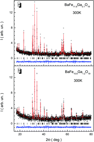
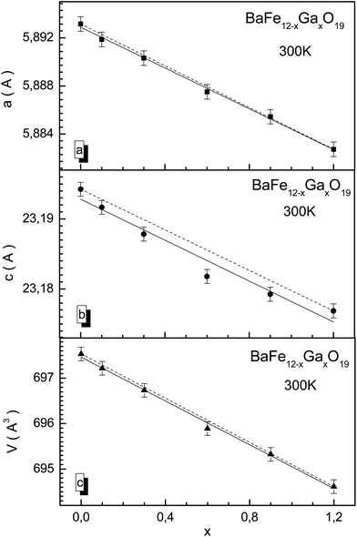
X-ray diffraction patterns for BaFe12−xGaxO19 solid solutions with x = 0.1 and 1.2 at room temperature are presented in Fig. 1. The X-ray diffraction data correspond to single-phase samples with a hexagonal unit cell crystal structure and P63/mmc space group, agreeing well with previous results obtained earlier for solid solutions with substitution by Al3+ and In3+ cations.37–39 The low values of the fitting parameters, such as Rwp (3.21–5.42), the weighted profile R-value, Rexp (2.41–5.36), the expected R-value, RB (5.42–8.65), the Bragg R-factor and χ2 (1.52–2.03), the goodness-of-fit quality factor, suggest that the studied sample is of good quality and that the refinements of the X-ray data have been effective.The a and c unit cell parameters are almost linear and they slightly decrease. In Fig. 2, results of calculations of the concentration dependencies of the unit cell parameters and volumes of all the BaFe12−xGaxO19 solid solutions are presented. The insignificant decreases in the unit cell parameters and, as a result, the unit cell volumes are caused by insignificant divergences of the values of the ionic radii of Ga3+ (0.62 Å) and Fe3+ (0.64 Å) cations.40 This behavior of the unit cell parameters is a consequence of the statistical distribution of Ga3+ cations in different nonequivalent crystallographic positions. For the c parameter, a slight deviation from Vegard's rule (Fig. 2a) is observed, which is due to the likely removal of the initial strain of the unit cell upon substitution. The initial strain occurs as a consequence of the rapid cooling of the ceramic after synthesis. The initial strain can be removed via substitution, as the ionic radius of the Ga3+ cation is slightly smaller than the ionic radius of the Fe3+ cation.
The model of the magnetic structure of barium hexaferrite proposed by Gorter41 assumes that the Fe3+ magnetoactive cations are located in nonequivalent crystallographic positions, which have octahedral (Fe1 – 2a, Fe4 – 4fVI and Fe5 – 12k), tetrahedral (Fe3 – 4fIV) and bipiramidal (Fe2 – 2b) oxygen surroundings. The Ba2+ cations occupy 2d sites with 12-fold oxygen coordination. The substitution of Fe3+ cations by diamagnetic Ga3+ cations, depending on the preference of the positions taken up by them, can lead to some reduction in the values of the magnetic moments in the corresponding nonequivalent crystallographic positions. Furthermore, the magnetic moments of these positions initially have the little difference in value because of the various oxygen coordinations.42 The substituted Ga3+ cations are distributed almost evenly among all five nonequivalent crystallographic positions.
The values of the main bond lengths and bond angles for the BaFe12−xGaxO19 solid solutions at room temperature are given in Table 1. As is shown, as the substitution level increases, the 4 bond lengths Fe2–O3, Fe3–O2, Fe4–O5 and Fe5–O1 decrease, while the remaining 5 bond lengths, Fe1–O4, Fe2–O1, Fe3–O4, Fe4–O3 and Fe5–O2, increase. The 3 bond angles Fe2–O3–Fe4, Fe5–O2–Fe5 and Fe5–O4–Fe5 decrease, while the other 3 bond angles, Fe3–O4–Fe5, Fe4–O3–Fe4 and Fe5–O1–Fe5, increase.
| Bond length/angle | x = 0.1 | x = 0.3 | x = 0.6 | x = 0.9 | x = 1.2 |
|---|---|---|---|---|---|
| Fe1–O4, Å | 1.982 | 1.992 | 2.014 | 2.028 | 2.047 |
| Fe2–O1, Å | 2.313 | 2.177 | 2.281 | 2.352 | 2.444 |
| Fe2–O3, Å | 1.806 | 1.818 | 1.844 | 1.861 | 1.834 |
| Fe3–O2, Å | 1.974 | 1.947 | 1.886 | 1.844 | 1.789 |
| Fe3–O4, Å | 1.914 | 1.916 | 1.919 | 1.921 | 1.924 |
| Fe4–O3, Å | 2.133 | 2.152 | 2.191 | 2.217 | 2.252 |
| Fe4–O5, Å | 1.983 | 1.977 | 1.965 | 1.956 | 1.944 |
| Fe5–O1, Å | 1.974 | 1.968 | 1.957 | 1.948 | 1.937 |
| Fe5–O2, Å | 2.062 | 2.076 | 2.106 | 2.125 | 2.152 |
| Fe2–O3–Fe4, ° | 138.66 | 138.09 | 136.91 | 136.12 | 135.04 |
| Fe3–O4–Fe5, ° | 120.66 | 121.14 | 122.18 | 122.81 | 123.75 |
| Fe4–O3–Fe4, ° | 82.86 | 83.94 | 86.24 | 87.89 | 90.05 |
| Fe5–O1–Fe5, ° | 98.65 | 98.84 | 99.23 | 99.48 | 99.84 |
| Fe5–O2–Fe5, ° | 89.74 | 89.38 | 88.59 | 88.05 | 87.33 |
| Fe5–O4–Fe5, ° | 88.73 | 83.47 | 72.81 | 65.80 | 56.29 |
The samples had densities of >98%, with an average size of ∼850 nm for the crystallites. The individual crystallites had the shape of regular planar hexagons (Fig. 3). The crystallites combine and form the entire ceramic. The crystallite sizes had certain differences. The grain size variation interval was between 0.223 and 1.279 μm for BaFe11.9Ga0.1O19. For this sample, 52.4% of the crystallites had a size variation from 0.740 μm to 0.860 μm. Crystallites with a size smaller than 0.170 μm or larger than 1.400 μm were not detected. The precise value of the average crystallite size for this sample, from quantitative stereologic analysis, was 〈D〉 ≈ 0.873 μM. With the substitution level increasing up to x = 1.2, the average crystallite size increased up to ∼950 nm.
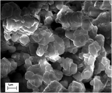 | ||
| Fig. 3 Typical surface topography obtained with the help of a scanning electron microscope at 300 K for the BaFe11.9Ga0.1O19 solid solution. | ||
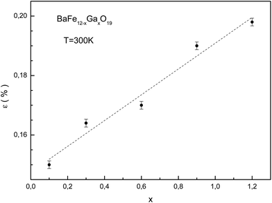
Upon substitution, microstrains in the crystal lattice and associated changes in the strain energy arise because of differences between the ionic radii of iron and gallium. Information regarding the microstrain was obtained from the diffraction line broadening. The dependencies of the W2 reflection-half-width square versus the d2 interplanar spacing square for the different substitution levels were examined at room temperature. This dependence is the approximating function. The line broadening increased as the substitution level increased. The full width at half maximum of the diffraction line was described as in ref. 39. The true physical contribution to the line broadening was determined using the FullProf program and was calculated as the difference in widths between the experimental samples and an Al2O3 standard. In the ferrimagnetic crystals, separate sublattices make different contributions to the general strain. Besides, the local environment symmetry of the magnetic cations in ferrimagnetic crystals differs from the macroscopic symmetry. This leads to an increase in the microscopic parameter numbers in comparison with the macroscopic ones. The slope of the approximating function increases as the substitution level increases. This behavior indicates that the microstrain increases in the crystallites.
The dependence of the microstrain value on the substitution level for the studied samples is shown in Fig. 4. The calculation of the microstrain was performed using an isotropic approximation, with size effects absent. The minimum microstrain is observed for the BaFe11.9Ga0.1O19 sample. The growth of microstrain with substitution level increase is associated with an increase in system disorder, as a result of the statistical distribution of the gallium cations in the magnetic sublattices. This can make different contributions to the total deformation. For the BaFe10.8Ga1.2O19 sample, a maximum ∼0.2% microstrain is observed.
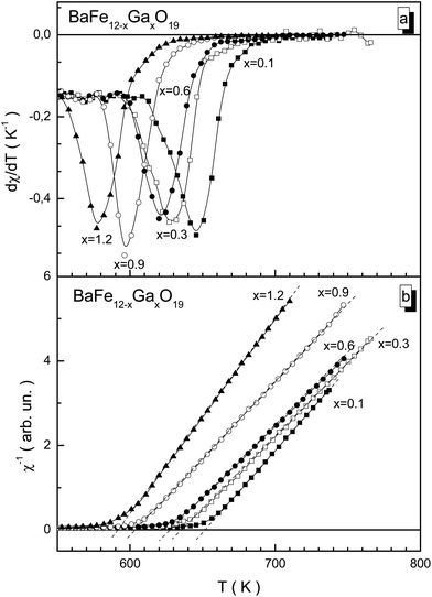
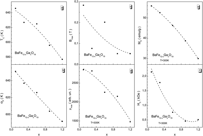
For the BaFe12−xGaxO19 samples, the ferrimagnetic–paramagnetic phase transition is usually a second order phase transition according to the temperature dependence of the susceptibility. With an increase in Ga3+ concentration, the temperature of the phase transition smoothly decreases from 646 K for x = 0.1 to 577 K for x = 1.2 (Fig. 5a), which is much lower than for the unsubstituted BaFe12O19 compound (TC = 740 K). This confirms that the substitution of Fe3+ cations by diamagnetic Ga3+ cations leads to a reduction in the number of magnetic neighbors of the iron cations, and, as a result, to earlier temperature destruction of the long-range magnetic order upon heating. Upon diamagnetic substitution, the frustration of the magnetic subsystem occurs. This is due to changes in bond lengths between the magnetoactive Fe3+ cations and O2− anions, with the partial distortion of the valency bond angles, which reduces the exchange interaction energy. Detailed information about the bond lengths and bond angles of the different nonequivalent crystallographic positions of the Fe3+ cations and O2− anions will be provided later in the next paper.
The reciprocal susceptibility is given in Fig. 5b. For all the samples, only positive values of the Θp paramagnetic Curie temperature are observed. This fact indicates the dominant character of the intrasublattice ferromagnetic exchange interactions. The Θp paramagnetic Curie temperature is an exchange parameter which determines the intensity of exchange interactions. For isotropic compounds with low uniaxial anisotropy, the TC Curie temperature is almost equal to the Θp paramagnetic Curie temperature, TC ∼ Θp. The high temperature susceptibility for all the samples obeys the modified Curie–Weiss law, χ = C/(T − Θp)γ.
For ferrimagnetic hexaferrite at temperatures slightly above TC (T > TC), the 1/χ(T) reciprocal value of the magnetic susceptibility has hyperbolic form, and only at temperatures much higher than TC (T ≫ TC) does it obey the Curie–Weiss law, i.e., it degenerates into a straight line. The hyperbolic temperature behavior of the reciprocal susceptibility at T > TC for the hexaferrite is a result of the effects of uniaxial exchange anisotropy. At temperatures slightly above TC in the hexaferrite, magnetic sublattices still exist. At the same time one of the sublattices is strong. Its magnetization is directed along the external B magnetic field. Other sublattices are weak. The magnetization of these sublattices is directed opposite to the external B magnetic field. As a result, in addition to the ferromagnetic paraprocess in the strong sublattice, antiferromagnetic paraprocesses in the weak sublattices occur. These antiferromagnetic paraprocesses in the weak sublattices lead to an underestimation of the value of the 1/χ(T) reciprocal susceptibility for the hexaferrite in the T > TC region.
The effective magnetic moment43 of the Fe3+ cation has been experimentally detected. It has been determined according to the relation μeff = (3kBC/n)1/2, where kB is the Boltzmann constant, n is the concentration of Fe3+ cations, and C is the Curie constant, determined as C = 1/tgγ, where γ is the slope angle of 1/χ. For BaFe11.9Ga0.1O19, the experimental value of the effective magnetic moment is ∼4.11μB. For BaFe10.8Ga1.2O19 the experimental value of the effective magnetic moment is ∼4.35μB. However, the theoretical effective moment is determined as μeff = g{S(S + 1)}1/2μB, where g is the gyromagnetic ratio, ∼2, S is the total spin of the Fe3+ cation, 5/2, and μB is the Bohr magneton. The theoretical effective moment is ∼5.92μB per Fe3+ cation for the parent unsubstituted BaFe12O19.
The C Curie constant changes non-monotonically with substitution level. Firstly it increases up to x = 0.6 and then it drops. The μeff ∼ C1/2 effective magnetic moment in the paramagnetic region (>740 K) behaves similarly to the Curie constant. It increases up to x = 0.6 and then it drops. This fact indicates that the decrease in the average magnetic moment per one Fe3+ magnetic cation upon substitution is the trend. The positive (ferromagnetic) Fe3+ O2− Fe3+ superexchange interactions in a particular magnetic sublattice are broken by the introduction of diamagnetic Ga3+ cations. The small increase in the effective magnetic moment is explained partly by the location of Ga3+ cations in different competing magnetic sublattices, which is confirmed by the Rietveld fitting.
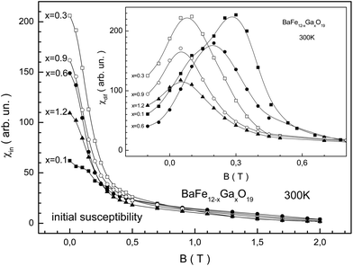
The behavior of the specific magnetization for the BaFe12−xGaxO19 samples from the field dependence indicates a decrease in the maximum magnetic energy as the substitution level increases. From Fig. 6 we can see that the largest initial susceptibility is observed for the sample with x = 0.3. The smallest initial susceptibility is observed for x = 0.1. The maximum value of the differential susceptibility decreases monotonically as the substitution level increases. Substitution by Ga3+ cations leads to a weakening of the stiffness of the intrasublattice Fe3+–O2−–Fe3+ superexchange interactions. This in turn leads to an increase in the initial magnetic susceptibility. However, the removal of the initial strain of the crystal structure with substitution increase prevents weakening of the stiffness of the superexchange interactions. Therefore the growth of the initial susceptibility is nonmonotonic. The Hmax induction value of the external magnetic field, at which the χmax = χ(Hmax) maximum value of the differential susceptibility is observed, decreases almost monotonically, excluding the x = 0.6 sample.
We have summarized the main magnetic characteristics in Fig. 7. As the substitution level increases, all the magnetic parameters decrease, showing a trend. Almost all of these magnetic parameters monotonically decrease. The TC Curie temperature and Θp paramagnetic Curie temperature are close. The latter is somewhat larger than the former (Fig. 7a and b). This indicates that strong positive Fe3+–O2−–Fe3+ superexchange interactions still exist in the different magnetic sublattices with the growth in substitution. The μ permeability is determined from the χ susceptibility as μ = 1 + 4πχ.
The Bmax induction value of the external magnetic field at which the μ permeability reaches the μmax maximum value, μmax = μ(Bmax), decreases from ∼0.3 T down to ∼0.05 T (Fig. 7c). One should pay attention to the change in the Bmax maximum magnetic induction. This value decreases non-monotonically with the substitution level increase. So, for the x = 0.3 sample this value decreases down to ∼0.08 T, and for the x = 0.6 sample it increases up to ∼0.2 T. It appears to oscillate with the substitution level increase. However, it decreases as a trend. Such behavior of Bmax can be caused by the quality of the ceramic, i.e., from the significant increase in the density of the ceramics and the value of microstrain for the x = 0.3 sample.
The largest μmax maximum permeability equal to ∼2850 in a field of ∼0.3 T is observed for the x = 0.1 sample (Fig. 7d). The smallest μmax maximum permeability equal to ∼1500 in a field of ∼0.05 T is observed for the x = 1.2 sample. It is noted that there is a monotonic decrease in remnant magnetization and coercivity (Fig. 7e and f). The MS spontaneous magnetization monotonically decreases from ∼56 emu g−1 when x = 0.1 down to ∼30 emu g−1 for when x = 1.2. The HC coercivity decreases from ∼2.2 kOe for x = 0.1 down to ∼0.5 kOe for x = 1.2 The lack of abrupt anomalies, i.e. deviations from the linear dependence of the magnetic energy decrease as the substitution level increases, on the temperature and field dependencies of the specific magnetization can be in favor of indicating the statistical distribution of Ga3+ cations between different nonequivalent crystallographic positions in the structure of the M-type barium hexaferrite.
In ref. 44 the expression determining the energy value of the electromagnetic radiation absorbed in a material is obtained. The Eabs absorbed energy is proportional to the sum of the imaginary parts of the ε′′ permittivity and μ′′ permeability as well as the frequency of the electromagnetic oscillations, i.e., it is determined by dielectric and magnetic losses. It is well known that the μ{ε} total complex permeability is determined as μ{ε} = μ′{ε′} + ιμ′′{ε′′}. This implies that upon the interaction of real materials with an electromagnetic field there are losses due to both μ′′ magnetic losses and ε′′ dielectric losses. The last category includes conduction currents and dielectric hysteresis phenomena that are taken into account by the permittivity. In the same work,44 it is shown that the absorption of electromagnetic energy in ferromagnetic materials is generally defined by the μ′′ magnetic losses, as a result of natural ferromagnetic resonance (NFR)45 and the resonance of domain borders.
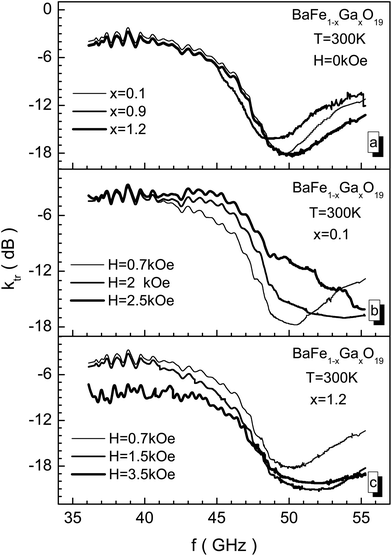
In Fig. 8, EMR transmission spectra through samples with different concentrations of Ga3+ cations, including in different bias fields, are presented. In the 46–50 GHz frequency range the most intensive absorption of electromagnetic waves caused by the NFR phenomenon is observed. The abscissa value of the global minimum of the EMR transmission spectrum determines fres, the resonant frequency of transmission. The ordinate value of the global minimum of the EMR transmission spectrum determines, Ares, the resonant amplitude of transmission. The global minimum width value measured at Ares/2, half of the resonant amplitude, determines the width of the Wres absorption band – the bandwidth. From Fig. 8 it is shown that all these three quantities are sensitive to the substitution level. The power of the transmission radiation decreases almost by 100 times.
The bias field also changes the amplitude-frequency characteristics of the NFR. The samples with a low substitution level are more sensitive to the bias field. At small values of bias field, a resonant frequency shift towards major frequencies is observed as a consequence of the increase of the internal effective anisotropy field. Upon this, the amplitude of the EMR transmission curve changes slightly. However, upon biasing the BaFe10.8Ga1.2O19 sample with the maximum substitution level, the amplitude of the EMR transmission curve also increases together with a NFR frequency increase (see Fig. 8c). The increase in the Ares resonant amplitude occurs up to a bias field of 1.5 kOe, and then the amplitude begins to decrease, corresponding to the behavior of the imaginary part of the permeability for the hexaferrite at the ferromagnetic resonance.
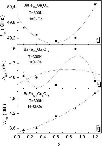
From Fig. 9 it is shown that as the substitution level increases, the value of the NFR frequency firstly decreases up to x = 0.6, and then its value increases. At x = 1.2, its value reaches a maximum fres value of 50.5 GHz (Fig. 9a). The Ares resonant amplitude changes non-monotonically. At x = 0.6, the minimum value of the resonant amplitude Ares of −18.5 dB (Fig. 9b) is observed. The Wres absorption band increases monotonically as the substitution level increases, and at x = 1.2 it reaches a maximum Wres value of 5 GHz (Fig. 9c).
The substitution of Fe3+ cations by Ga3+ cations up to x = 0.6 leads to a weakening of the stiffness of the intrasublattice Fe3+–O2−–Fe3+ superexchange interactions. This decreases the fres resonant frequency and the Ares resonant amplitude. However, removing the initial strain of the crystal structure as the substitution level increases up to x = 1.2 prevents the weakening of the stiffness of the superexchange interactions. And the fres resonant frequency and Ares resonant amplitude decrease.
The sharp increase in the Ares resonant amplitude for the x = 0.9 sample may be associated with a non-uniform distribution of Ga3+ cations over nonequivalent crystallographic positions. And as a result of this non-uniform distribution of Ga3+ cations, a sharp decrease in the uniaxial exchange anisotropy is observed. Therefore, the substitution level increase leads to the non-monotonic behavior of the amplitude-frequency characteristics of the natural ferromagnetic resonance. The decrease in uniaxial exchange anisotropy has no appreciable effect on the Wres absorption band and then it monotonically increases.
The dashed lines in Fig. 9 indicate the fitting of the experimental values by a second order polynomial of the y(x) = A*x2 + B*x + C type. The dotted line in Fig. 9b indicates the fitting of the experimental values by a third order polynomial of the y(x) = D*x2 + E*x2 + F*x + G type. The interesting case is the case relating to the Ares resonant amplitude for the x = 0.9 sample. This sample had a large −16 dB value for the Ares resonant amplitude. So an attempt has been made to describe the concentration dependence of the Ares resonant amplitude using polynomials of two kinds, both second and third order. The second order polynomial was given by an equation of the form Ares(x) = −18.47 + 2.63x − 1.66x2. The third-order polynomial was given by an equation of the form Ares(x) = −16.30 + 16.88x + 35.57x2 − 18.97x3. The smallest error between the experimental and theoretical values is observed in the case of the third-order polynomial.
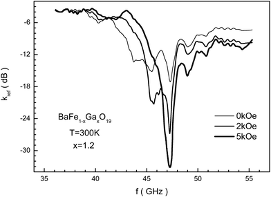
In Fig. 10 the frequency dependence of the reflection loss is presented in decibels for the BaFe10.8Ga1.2O19 sample, including in different bias fields measured using the matched load mode. This dependence has difficult behavior to explain. It is possible to note that as the bias field increases, the losses increase, and in a field of 5 kOe the minimum value for kref of −33 dB is reached. The reflected EMR energy decreases by more than 3 orders. A further increase in the bias field leads to a decrease in the resonant curve intensity. Upon this, the frequency of the resonant curve of reflection loss almost doesn't change.
In Fig. 11, the dependence of the NFR frequency for the studied samples on the bias field is presented. An increase in the resonant frequency as the bias field increases is observed since the internal anisotropy field increases. This dependency has almost linear behavior for all the samples. The resonant frequency is most sensitive to the bias field for samples with a small Ga3+ cation concentration. While for almost all the samples the resonant frequency increases approximately to 1.5 GHz as the bias field increases to 1 kOe, for the sample with x = 0.1 the resonant frequency increases to 2.2 GHz.
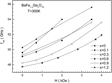 | ||
| Fig. 11 The external magnetic bias field dependence of the fres(H) NFR frequency at T = 300 K for BaFe12−xGaxO19 (x = 0; 0.1; 0.3; 0.6; 0.9; and 1.2) solid solutions. | ||
In the search for materials which are effectively working in the microwave range, the region involving NFR is of the greatest interest. Ferromagnetic resonance leads to energy losses in the electromagnetic field, which are a result of a number of processes such as cation spin precession for ferro- or ferrimagnets, connected with additional fluctuations of the crystal lattice sites.46 The spin precession from NFR occurs under the influence of internal local magnetic fields as a result of their own magnetic anisotropy.47 The M magnetization vector precesses around the easy direction so as if it is affected by a magnetic field – the anisotropy field. The physical principles responsible for the NFR losses are the same as for the induced ferromagnetic resonance. These are the additional fluctuations of the crystal lattice sites of the hexaferrite under the influence of spin waves. The interaction of spin waves with a crystal lattice leads to the fact that a part of the external alternating field energy excites thermal spin precession, and hence the spin waves, turning into thermal fluctuations of the lattice. Upon this, the NFR frequency is defined as the rotational stiffness of the magnetization vector in the plane of the easy direction and the rotational stiffness out of this plane.48
Obtaining samples with the certain physical properties required for effective absorption is usually reached by the substitution of Fe3+ cations by diamagnetic and (or) paramagnetic ions. As the substitution level of the hexaferrite by Sc3+, Ti4+ and Co2+, and Ti4+ and Zn2+ cations increases,49 it has been established that there is a decrease in the saturation magnetization, Curie temperature and magnetocrystalline anisotropy that is connected with a reduction in the number of magnetic cations. The decrease in the resonant frequency is a consequence of the anisotropy field decrease. However, substitution by Al3+ cations, along with a decrease in the saturation magnetization and Curie temperature, leads to an increase in the resonant frequency that is connected with an increase in the magnetocrystalline anisotropy field.50 An increase in the resonant frequency is also noted upon an increase in the substitution level by Cr3+ cations for barium and strontium hexaferrites.51
An analysis52 of the amplitude-frequency characteristics of absorption losses in substituted hexaferrites shows the opportunity to control the NFR frequency and frequency shifts through changes in the x substitution level. It is proposed53 to approximate resonant frequency changes versus the Ti3+ and Co3+ cation concentration for x = 0–3.5 using a polynomial of second order in the following form:
| fres(x) = fres(0) + A*x2 + B*x, | (2) |
In our case, the concentration dependence of the resonant frequency is non-monotonic and it also characterized by a minimum at x = 0.6. This dependence can be well approximated using a polynomial of second order in the following form:
| fres(x) = 50.04 + 3.37x2 − 3.73x, | (3) |
This means that the resonant frequency firstly decreases with a substitution level increase up to x ≈ 0.55, and then it increases. Such concentration behavior is observed for the monotonic decrease of magnetic parameters such as the Curie temperature, spontaneous magnetization and coercive force with the growth of Ga3+ cation concentration.54
As the substitution level increases, the spontaneous magnetization decreases, while the magnetocrystalline anisotropy field increases. At low (x ≤ 0.3) substitution values, the magnetization decrease leads to an increase in the initial susceptibility and permeability. The magnetization decrease dominates the increase in the magnetocrystalline anisotropy. Thus the increase in the fres resonant frequency at x ≥ 0.6 is caused by an increase in the magnetocrystalline anisotropy. Substitution up to x = 0.6 leads to a weakening of the stiffness of the intrasublattice Fe3+–O2−–Fe3+ superexchange interactions. The fres resonant frequency and the Ares resonant amplitude decrease as a result of weakening stiffness in the exchange interactions. The main role in the Wres line broadening is played by static inhomogeneities such as impurity cations. As the substitution increases, the Wres line widths monotonically increase. As the samples have been obtained at the same time and using identical technology, they have identical morphologies in their crystallites. Therefore it is possible to assume that the contribution to the EMR absorption by domain border resonance is not of important value. It poorly depends on the substitution concentration.55
The kabs EMR absorption coefficient can be calculated from the experimentally obtained ktr transmission and kref reflection coefficients, taking into account the energy conservation law using the formula:
| kabs = 10 lg(1 − 100.1ktr − 100.1kref), | (4) |
All the coefficients are negative, which indicates the reduction of the EMR energy after interaction with the substance. Moreover in practice it is necessary to obtain greatly negative values of the ktr transmission and kref reflection coefficients, to achieve significant weakening of the transmitted and reflected EMR energies.56 For this, the kabs EMR absorption coefficient will be slightly negative. In our case, the absorption coefficient in a zero bias field is k0abs = −0.09. In a bias field of 5 kOe, the absorption coefficient increases up to k5abs = −0.05. This indicates that almost all the incident EMR energy is absorbed, and in a field of 5 kOe the absorption maximum is observed. Such substances with large negative values of ktr transmission and kref reflection coefficients, and small negative values of kabs absorption coefficient have good prospects for the creation of a protective antiradar covering of air force objects according to “Stealth” technology.57–59
4. Conclusions
Investigations into the crystal structures of BaFe12−xGaxO19 (x = 0.1; 0.3; 0.6; 0.9; and 1.2) solid solutions of ceramic samples are conducted using the X-ray diffraction method with Cu-Kα radiation. All the studied compositions correspond to single-phase samples with a hexagonal crystal structure and P63/mmc space group of symmetry. The isotropic and almost linear reduction of the unit cell parameters is caused by the statistical distribution of diamagnetic substitution cations throughout all the ionic positions, such as octahedral, tetrahedral and bipyramidal anion surroundings, because of the proximities of the ionic radii of Fe3+ (0.64 Å) and Ga3+ (0.62 Å). The ferrimagnetic–paramagnetic phase transition in the BaFe12−xGaxO19 samples is a second order one. The temperature of this phase transition, upon an increase in Ga3+ cation concentration, smoothly decreases from 646 K (for x = 0.1) to 577 K (for x = 1.2), which is caused by a decrease in the bond number of the magnetoactive iron cations with the oxygen anions. The magnetization behavior of the samples indicates a decrease in the energy of the Fe3+–O2−–Fe3+ exchange interactions upon an increase in Ga3+ cation concentration. The lack of anomalies in the temperature and field dependencies of specific magnetization favorably suggests the statistical distribution of Ga3+ cations throughout all the sublattices in the structure. The conducted research into the absorbing properties has shown the noticeable influence of diamagnetic substitution on the microwave characteristics of the studied samples. As the substitution level increases, the NFR frequency firstly decreases from 49.6 GHz down to 49.2 GHz at x = 0.6 and then the NFR frequency increases up to 50.6 GHz at x = 1.2. Upon this, the intensity of the resonant curves changes slightly. The application of a bias field considerably shifts the resonant frequency of the samples at small Ga3+ cation concentrations towards major frequencies. The substitution of the Fe3+ cations by Ga3+ cations increases the frequency range over which the intensive absorption of electromagnetic energy is observed, as is required for protective antiradar shielding from microwave radiation.Acknowledgements
The present work is realized as a result of joint financing from the Ministry of Education and Science of the Russian Federation for the program of Increase of Competitiveness of NITU “MISIS” among the leading world scientific and educational centers (No. K4-2015-040, No. K3-2016-019, No. K3-2017-028 and No. K4-2017-041), with support from and within the state orders of the Russian Federation Government on the organization of scientific work, and with assistance from the grants BRFBR (No. F17D-003) and JINR (No. 04-4-1121-2015/2017). In SUSU this work was supported by the Ministry of Education and Science of the Russian Federation (4.1346.2017/4.6) by Act 211 of the Government of the Russian Federation (contract No. 02.A03.21.0011). L. Panina acknowledges support under a Russian Federation State contract for organizing scientific work.References
- T. Xie, L. Xu, C. Liu, J. Yang and M. Wang, Dalton Trans., 2014, 43, 2211 RSC.
- Z. Durmus, A. Durmus and H. Kavas, J. Mater. Sci., 2015, 50, 1201 CrossRef CAS.
- T. A. Kaplan and N. Menyuk, Philos. Mag., 2007, 87, 3711 CrossRef CAS.
- G. Albanese, F. Leccabue, B. E. Watts and S. Díaz-Castañón, J. Mater. Sci., 2002, 37, 3759 CrossRef CAS.
- L. Wang, H. Yu, X. Ren and G. Xu, J. Alloys Compd., 2014, 588, 212 CrossRef CAS.
- P. Meng, K. Xiong, L. Wang, S. Li, Y. Cheng and G. Xu, J. Alloys Compd., 2015, 628, 75 CrossRef CAS.
- A. M. Y. El-Lawindy, S. A. Mansour, M. Hafiz, H. H. Hassan and A. A. Ali, Int. J. Appl. Ceram. Technol., 2010, 7, 868 CrossRef CAS.
- X. Liu, J. Wang, L. M. Gan, S. C. Ng and J. Ding, J. Magn. Magn. Mater., 1998, 184, 344 CrossRef CAS.
- D. A. Vinnik, A. B. Ustinov, D. A. Zherebtsov, V. V. Vitko, S. A. Gudkova, I. Zakharchuk, E. Lähderanta and R. Niewa, Ceram. Int., 2015, 41, 12728 CrossRef CAS.
- J. J. Went, G. W. Rathenau, E. W. Gorter and G. W. van Oosterhout, Phys. Rev., 1952, 86, 424 CrossRef CAS.
- R. C. Pullar, Prog. Mater. Sci., 2012, 57, 1191 CrossRef CAS.
- E. Richter, T. J. E. Miller, T. W. Neumann and T. L. Hudson, IEEE Trans. Ind. Appl., 1985, 1A-21, 644 CrossRef.
- J. Smit and H. G. Beljers, Philips Res. Rep., 1955, 10, 113 CAS.
- J. O. Artman, Proc. IRE, 1956, 44, 1284 CrossRef CAS.
- Q. A. Pankhurst and R. S. Pollard, J. Phys.: Condens. Mater., 1993, 5, 8487 CrossRef CAS.
- Y. Tokunaga, Y. Kaneko, D. Okuyama, S. Ishiwata, T. Arima, S. Wakimoto, K. Kakurai, Y. Taguchi and Y. Tokura, Phys. Rev. Lett., 2010, 105, 257201 CrossRef CAS PubMed.
- G. Tan and X. Chen, J. Magn. Magn. Mater., 2013, 327, 87 CrossRef CAS.
- A. V. Trukhanov, V. O. Turchenko, I. A. Bobrikov, S. V. Trukhanov, I. S. Kazakevich and A. M. Balagurov, J. Magn. Magn. Mater., 2015, 393, 253 CrossRef CAS.
- V. G. Kostishyn, L. V. Panina, L. V. Kozhitov, A. V. Timofeev and A. N. Kovalev, J. Alloys Compd., 2015, 645, 297 CrossRef CAS.
- S. V. Trukhanov, A. V. Trukhanov, V. G. Kostishin, L. V. Panina, I. S. Kazakevich, V. A. Turchenko and V. V. Kochervinskiy, JETP Lett., 2016, 103, 100 CrossRef CAS.
- V. G. Kostishyn, L. V. Panina, A. V. Timofeev, L. V. Kozhitov, A. N. Kovalev and A. K. Zyuzin, J. Magn. Magn. Mater., 2016, 400, 327 CrossRef CAS.
- L. Li, K. Chen, H. Liu, G. Tong, H. Qian and B. Hao, J. Alloys Compd., 2013, 557, 11 CrossRef CAS.
- V. A. Turchenko, A. V. Trukhanov, S. V. Trukhanov, I. A. Bobrikov and A. M. Balagurov, Eur. Phys. J. Plus, 2016, 131, 82 CrossRef.
- S. V. Trukhanov, A. V. Trukhanov, A. N. Vasiliev and H. Szymczak, JETP, 2010, 111, 209 CrossRef CAS.
- N. Velhal, G. Kulkarni, D. Mahadik, P. Chowdhury, H. Barshilia and V. Puri, J. Alloys Compd., 2016, 682, 730 CrossRef CAS.
- M. Labeyrie, J. C. Mage, W. Simonet, J. M. Desvignes and H. Le Gall, IEEE Trans. Magn., 1984, Mag-20, 1224 CrossRef CAS.
- P. Röschmann, M. Lemke, W. Tolksdorf and F. Welz, Mater. Res. Bull., 1984, 19, 385 CrossRef.
- A. V. Trukhanov, L. V. Panina, S. V. Trukhanov, V. A. Turchenko and M. Salem, Chin. Phys. B, 2016, 25, 016102 CrossRef.
- H. M. Rietveld, J. Appl. Crystallogr., 1969, 2, 65 CrossRef CAS.
- http://www.ill.eu/sites/fullprof/ .
- S. V. Trukhanov, A. V. Trukhanov, S. G. Stepin, H. Szymczak and C. E. Botez, Phys. Solid State, 2008, 50, 886 CrossRef CAS.
- A. V. Trukhanov, S. V. Trukhanov, L. V. Panina, V. G. Kostishyn, I. S. Kazakevich, An. V. Trukhanov, E. L. Trukhanova, V. O. Natarov, V. A. Turchenko, M. M. Salem and A. M. Balagurov, J. Magn. Magn. Mater., 2017, 426, 487 CrossRef CAS.
- S. V. Trukhanov, A. V. Trukhanov, C. E. Botez, A. H. Adair, H. Szymczak and R. Szymczak, J. Phys.: Condens. Matter, 2007, 19, 266214 CrossRef CAS PubMed.
- S. V. Trukhanov, A. V. Trukhanov, V. G. Kostishyn, L. V. Panina, V. A. Turchenko, I. S. Kazakevich, An. V. Trukhanov, E. L. Trukhanova, V. O. Natarov and A. M. Balagurov, J. Magn. Magn. Mater., 2017, 426, 554 CrossRef CAS.
- S. V. Trukhanov, A. V. Trukhanov, A. N. Vasiliev, A. M. Balagurov and H. Szymczak, JETP, 2011, 113, 819 CrossRef CAS.
- S. V. Trukhanov, A. V. Trukhanov, A. N. Vasil'ev, A. Maignan and H. Szymczak, JETP Lett., 2007, 85, 507 CrossRef CAS.
- V. A. Turchenko, A. V. Trukhanov, I. A. Bobrikov, S. V. Trukhanov and A. M. Balagurov, Crystallogr. Rep., 2015, 60, 629 CrossRef CAS.
- S. V. Trukhanov, A. V. Trukhanov, V. O. Turchenko, V. G. Kostishin, L. V. Panina, I. S. Kazakevich and A. M. Balagurov, J. Magn. Magn. Mater., 2016, 417, 130 CrossRef CAS.
- S. V. Trukhanov, A. V. Trukhanov, V. A. Turchenko, V. G. Kostishyn, L. V. Panina, I. S. Kazakevich and A. M. Balagurov, J. Alloys Compd., 2016, 689, 383 CrossRef CAS.
- R. D. Shannon, Acta Crystallogr., Sect. A: Cryst. Phys., Diffr., Theor. Gen. Cryst., 1976, 32, 751 CrossRef.
- E. W. Gorter, Proc. IRE, 1955, 43, 1945 CrossRef CAS.
- S. V. Trukhanov, J. Mater. Chem., 2003, 13, 347 RSC.
- A. Sundaresan, A. Maignan and B. Raveau, Phys. Rev. B: Condens. Matter, 1997, 56, 5092 CrossRef CAS.
- L. D. Landau, L. P. Pitaevskii and E. M. Lifshitz, Electrodynamics of Continuous Media, Butterworth-Heinemann, 2nd edn, 1984, p. 253 Search PubMed.
- A. J. E. Welch, P. F. Nicks, A. Fairweather and F. F. Roberts, Phys. Rev., 1950, 77, 403 CrossRef CAS.
- L. Ne'el, Ann. Phys., 1948, 3, 137 Search PubMed.
- A. V. Trukhanov, S. V. Trukhanov, L. V. Panina, V. G. Kostishyn, D. N. Chitanov, I. S. Kazakevich, An. V. Trukhanov, V. A. Turchenko and M. Salem, Ceram. Int., 2017, 43, 5635 CrossRef.
- C. Kittel, Phys. Rev., 1948, 73, 155 CrossRef CAS.
- J. Smith and H. P. J. Wijn, Ferrites, John Willey and Sons, New York, Eindhoven, 1959, p. 321 Search PubMed.
- L. G. Van Uitert, J. Appl. Phys., 1955, 26, 1289 CrossRef CAS.
- M.El. Rayess, J. B. Sokoloff, C. Vittoria and W. Spurgeon, J. Appl. Phys., 1990, 67, 5527 CrossRef CAS.
- R. S. Alam, M. Moradi, M. Rostami, H. Nikmanesh, R. Moayedi and Y. Bai, J. Magn. Magn. Mater., 2015, 381, 1 CrossRef CAS.
- L. L. Eremtsova, I. Nedkov, V. P. Cheparin and A. A. Kitaytsev, Inorg. Mater., 1972, 8, 59 Search PubMed.
- I. Bsoul and S. H. Mahmood, J. Alloys Compd., 2010, 489, 110 CrossRef CAS.
- J. Chen, P. Meng, M. Wang, G. Zhou, X. Wang and G. Xu, J. Alloys Compd., 2016, 679, 335 CrossRef CAS.
- S. V. Trukhanov, A. V. Trukhanov, H. Szymczak, C. E. Botez and A. Adair, J. Low Temp. Phys., 2007, 149, 185 CrossRef CAS.
- S. P. Mahulikar, H. R. Sonawane and G. A. Rao, Prog. Aeronaut. Sci., 2007, 43, 218 CrossRef.
- V. D. Doroshev, V. A. Borodin, V. I. Kamenev, A. S. Mazur, T. N. Tarasenko, A. I. Tovstolytkin and S. V. Trukhanov, J. Appl. Phys., 2008, 104, 093909 CrossRef.
- V. V. Atuchin, D. A. Vinnik, T. A. Gavrilova, S. A. Gudkova, L. I. Isaenko, X. Jiang, L. D. Pokrovsky, I. P. Prosvirin, L. S. Mashkovtseva and Z. Lin, J. Phys. Chem. C, 2016, 120, 5114 CAS.
| This journal is © The Royal Society of Chemistry 2017 |

