Diethylenetriamine-mediated self-assembly of three-dimensional hierarchical nanoporous CoP nanoflowers/pristine graphene interconnected networks as efficient electrocatalysts toward hydrogen evolution†
Xiuling
Fan
ab,
Xiaoyan
Wang
ab,
Weiyong
Yuan
 *ab and
Chang Ming
Li
 ab
ab
aInstitute for Clean Energy & Advanced Materials, Faculty of Materials & Energy, Southwest University, Chongqing 400715, China. E-mail: yuanweiyong@swu.edu.cn
bChongqing Key Laboratory for Advanced Materials and Technologies of Clean Energies, Chongqing 400715, China
First published on 9th October 2017
Abstract
Highly active, durable, and low-cost hydrogen evolution reaction (HER) catalysts are critical for large-scale energy storage in the form of hydrogen through water splitting but their fabrication presents great challenges. Herein we report the synthesis of a novel 3D hierarchical nanoporous CoP nanoflowers/pristine graphene interconnected network structure via diethylenetriamine (DETA)-mediated self-assembly, in which DETA promoted the uniform dispersion of graphene and the nucleation of the CoP precursor on graphene, the seed aggregation facilitated the formation of nanoflowers and a 3D network, and the gas release during the low-temperature phosphidation produced nanopores inside the nanoflowers. This nanoarchitecture shows an onset potential of −0.014 V, an overpotential of 98.1 mV to achieve 10 mA cm−2, a Tafel slope of 40.9 mV dec−1, and an exchange current density of 0.119 mA cm−2. The onset overpotential, overpotential to achieve 10 mA cm−2, and Tafel slope are all among the lowest reported for non-noble metal hydrogen evolution reaction (HER) catalysts, and the exchange current density also compares favorably to those of most reported HER catalysts. In addition, the catalyst exhibits excellent durability with negligible loss in current density after 2000 cyclic voltammetry (CV) cycles (+0.01 to −0.17 V vs. the RHE, at a scan rate of 100 mV s−1) or 23.5 h of chronoamperometric measurement at an overpotential of 98.1 mV, and a high faradaic efficiency of close to 100%. This work not only creates a high-performance and inexpensive HER electrocatalyst by utilizing the great advantages of 3D hierarchically nanostructured networks, but also develops a facile and economical strategy for the self-assembly of hierarchical nanostructures and offers scientific insight into its mechanism.
Introduction
The storage of renewable but intermittent energy forms such as solar, wind, and tidal energy in the covalent bonds of hydrogen through electricity, sunlight, or mechanical force-driven water splitting presents a highly promising strategy to solve today's energy crisis.1–5 The efficiency of this process is critically dependent on the hydrogen evolution reaction (HER).5–7 Pt-group metals are the most efficient and widely used HER catalysts but are very scarce and expensive.7,8 Ni based alloys have also been commercially used as HER catalysts. However, they easily corrode and are thus unstable under acidic conditions, which are required for important applications such as polymer electrolyte membrane (PEM) based water splitting and regenerative fuel cells.1,7,9,10 Therefore, a great deal of attention has been paid to the development of earth-abundant, low-cost, and acid-stable ones.6–8,11–14 In particular, transition metal phosphides (TMPs) such as CoP, Ni2P, and FeP have attracted much interest because of their higher intrinsic catalytic activities than those of conventional non-noble-metal-based catalysts and good stability in acid media. However, it is still challenging to significantly boost the performance of these TMP-based catalysts for large-scale practical applications, possibly due to the unfavorable structures of conventional TMPs at different length scales and in different directions, limiting accessible active sites, restricting mass diffusion, and/or retarding electron transfer/transport.5,15,16The hierarchical nanostructures of TMPs could greatly enhance their HER catalytic performance since they can not only exhibit unique shape-dependent properties, but also significantly increase the surface area via the smaller structure and facilitate the ionic and molecular diffusion via the larger one.15–17 Further assembly of them into 3D interconnected networks could maintain these great advantages, and even introduce additional ones such as accelerated electron transfer and transport and enhanced structural stability due to significantly improved structural connectivity in various directions, thus further improving the HER activity and durability.15,18,19 However, it is a formidable challenge to realize the 3D assembly of TMP hierarchical nanostructures for high catalytic performance without the addition of any linkers since the large and rigid TMP structures prevent their intimate contact for robust assembly and the interactions between these structures are not strong enough for their uniform and efficient assembly.20–23 Although multivalent linkers such as polymers and nanoparticles could enhance the 3D assembly, they are not effective due to the size/geometry mismatch, lack of strong interactions with the TMP/TMP precursor hierarchical nanostructures, and possible adverse effects on the electron transfer/transport properties.20,24,25
Graphene holds great promise as an ideal spacer and linker for fabricating 3D interconnected networks of TMP hierarchical nanostructures since its micrometer-sized 2D structure with high flexibility could create a large interface with TMP structures and generate strong interactions, and its excellent conductivity could greatly facilitate the electron transfer and transport.26–28 One potential approach to realizing this graphene-assisted 3D assembly could be the pre-synthesis of TMP/TMP precursor hierarchical nanostructures followed by integration with graphene.18,26 Nevertheless, it is challenging for large nanostructures such as micrometer sized hierarchical nanostructures to be assembled with pristine graphene since graphene is notoriously inert owing to its scarce functional groups resulting in very weak interaction, and although graphene oxide (GO) or strongly oxidized graphene could be used, it would result in compromised performance even after sophisticated reduction under severe reducing conditions because of the irreversibly damaged electronic structure.29–31 Alternatively, the direct synthesis of TMP/TMP precursor hierarchical nanostructures using graphene as a mediator is promising since it can not only avoid the pre-synthesis step to greatly simplify the fabrication process but also generate an intimate contact between TMP hierarchical nanostructures and graphene through in situ nucleation and growth.26,32 However, it is rather difficult for TMPs/TMP precursors to nucleate and grow on extremely inert pristine graphene.1,29,30 It is even more so to grow TMP/TMP precursor hierarchical nanostructures and simultaneously form 3D graphene-integrated interconnected networks during the in situ synthesis process.18,33,34
Self-assembly is a facile, economical, scalable, and environment-friendly approach for the fabrication of various nanoarchitectures.35–38 In particular, self-assembly mediated via small organic molecules is highly promising for the preparation of electrocatalysts, since specifically chosen molecules can not only play multiple roles such as stabilizers and linkers and promote the conformal assembly of uniform nanostructures on various substrates, but also maintain the conductivity of the final product much better than polymers due to their small size.39–41 In this study, for the first time a 3D hierarchical nanoporous CoP nanoflower network interconnected by pristine graphene was directly synthesized via a novel diethylenetriamine (DETA)-mediated self-assembly strategy followed by low-temperature phosphidation. The nanoporous nanoflowers are employed as a building block since a nanoflower is a typical hierarchical structure that has a higher-level flower-like structure composed of nanorods or nanosheets as the petals,23,42,43 and the introduction of nanopores into the nanoflowers adds another level of hierarchy.44,45 The possible mechanism of this self-assembly process was systematically studied based on experimental observations. Further, its application as an HER catalyst was investigated.
Experiment section
Materials
High-purity pristine graphene (>99.4%, oxygen content ∼1.0 wt%) was obtained from Sinocarbon Materials Technology Co., Ltd. Sodium hypophosphite was purchased from Aladdin. Ammonium fluoride, urea, Co(NO3)2·6H2O, DETA and Nafion (5 wt%) were purchased from Sigma-Aldrich. A commercial Pt/C catalyst (30 wt%) was bought from E-TEK. The deionized (DI) water used throughout all experiments was purified through a Milli-Q water purification system (Millipore).Synthesis of the 3D Co(OH)F nanoflowers/graphene interconnected network (3D Co(OH)F NFs/G IN)
5 mg graphene was dispersed in 30 mL of a mixed solvent of DETA and DI water (the concentration of DETA is 1.05% (v/v)) via ultrasonication to form a homogeneous dispersion. Subsequently, 1 g Co(NO3)2·6H2O, 3 g urea, and 5 g NH4F were dissolved in the above suspension, which was then transferred to a stainless-steel autoclave of 50 mL capacity and heated at 150 °C for 6 h. After the autoclave was cooled to room temperature naturally, the product was collected by centrifugation, washed with ethanol and DI water several times, and then dried in a vacuum oven at 60 °C for 12 h.Synthesis of the 3D hierarchical nanoporous CoP nanoflowers/graphene interconnected network (3D NP-CoP NFs/G IN)
The 3D NP-CoP NFs/G IN was synthesized using the 3D Co(OH)F/G IN as the precursor. Typically, 10 mg of Co(OH)F/G IN and 0.2 g of NaH2PO2 were put at two separate positions in a porcelain boat with NaH2PO2 at the upstream side of a tube furnace. Subsequently, the product was heated to 300 °C with a heating rate of 2 °C min−1 and maintained at 300 °C for 2 h in an Ar atmosphere and then naturally cooled to ambient temperature.Characterization
X-ray photoelectron spectra (XPS) were recorded on a Thermo Scientific ESCALAB 250Xi X-ray photoelectron spectrometer, using Al Kα radiation as the excitation source. Field emission scanning electron microscopy (FESEM) imaging was performed on a JEOL JSM-7800F microscope. X-ray powder diffraction (XRD) patterns were obtained using a Shimadzu XRD-7000 diffractometer with a Cu Kα line. Transmission electron microscopy (TEM) and high-resolution TEM (HRTEM) images were taken on a JEOL JEM-2100 microscope.Electrochemical measurements
All electrochemical measurements were performed in a three-electrode system with 0.5 M H2SO4 on a CHI660E electrochemical workstation (CH Instruments, Inc., USA). A saturated calomel electrode (SCE) and a platinum foil were used as reference and counter electrodes, respectively. To exclude the effect of the counter electrode on the performance, a graphite rod (3 mm, Tianjin Aida) was also used as the counter electrode. For the fabrication of the working electrode, 0.5 mg of the catalyst was dispersed in a mixed solution of 0.475 mL ethanol and 0.025 mL 5% Nafion by sonication, and then 60 μL of the catalyst suspension was dropped onto the surface of the GC electrode and dried under an infrared lamp. Linear sweep voltammetry (LSV) was conducted at a scan rate of 2 mV s−1. Cyclic voltammetry (CV) was performed in the potential range between +0.01 V and −0.17 V at 100 mV s−1. Electrochemical impedance spectra (EIS) were obtained at an overpotential of 200 mV in a frequency range from 1 Hz to 1 MHz with an amplitude of 10 mV. All the electrochemical data are presented with overpotentials iR corrected. All the potentials are reported against the reversible hydrogen electrode (RHE). In 0.5 M H2SO4, E(RHE) = E(SCE) + 0.259 V, based on the RHE calibration experiment.2Hydrogen production measurement
The amount of hydrogen produced during electrochemical water splitting was measured via an online gas chromatograph (GC-2014, Shimadzu). The cell setup was the same as that used for electrochemical measurements. The cathode potential was maintained at −0.15 V.Results and discussion
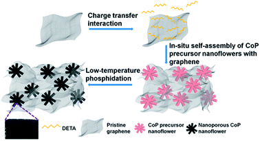
The fabrication process of 3D H-NP-CoP NF/G IN is schematically shown in Fig. 1. First, pristine graphene was dispersed in DETA solution to form a homogeneous suspension via charge transfer interaction.46,47 Then, the 3D interconnected network structure of CoP precursors was fabricated via DETA-mediated self-assembly with graphene under hydrothermal conditions. Finally, the 3D H-NP-CoP NF/G IN was obtained via low-temperature phosphidation.The uniform dispersion of building blocks is critical for their self-assembly. Pristine graphene can be dispersed easily in an aqueous solution of DETA (1–2 min bath sonication is enough for homogeneous dispersion) and it can maintain the dispersion state for at least 12 h (Fig. 2A). In contrast, it is very challenging to disperse pristine graphene in DI water, and even after vigorous ultrasonication, graphene is much more easily aggregated and precipitated (Fig. 2A). The much enhanced dispersion of graphene clearly indicates that there is a strong interaction between graphene and DETA, which arises from electron transfer from DETA to graphene.46,47 This kind of charge transfer interaction not only helps to break the strong van der Waals interaction between graphene nanosheets to facilitate their dispersion, but also promotes the formation of DETA modified graphene nanosheets to prevent their restacking (Fig. 2B).
 | ||
| Fig. 2 (A) Photographs of graphene dispersed in DETA solution (left) and DI water (right) after 12 h. (B) Possible process of the dispersion of graphene in DETA solution. | ||
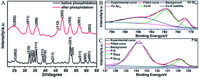
The graphene suspension was then mixed with other reactants for DETA-mediated self-assembly. Fig. 3A displays the XRD patterns of the products before and after phosphidation. For the one before phosphidation, besides the graphite peak (C(002)) from graphene, several characteristic peaks of orthorhombic Co(OH)F (JCPDS card no. 50-0827) are identified.48,49 However, for the one after phosphidation, only the C(002) peak and characteristic peaks of orthorhombic CoP (JCPDS card no. 29-0497) are observed.1,2 These results indicate the successful chemical conversion of Co(OH)F into CoP. Fig. 3B and C show the high-resolution Co 2p3/2 and P 2p XPS spectra of the sample after phosphidation, respectively. The high-resolution Co 2p3/2 spectrum (Fig. 3B) shows three peaks at 779.0, 781.7, and 785.9 eV, whereas the P 2p spectrum (Fig. 3C) exhibits three peaks at 129.8 (P 2p3/2), 130.6 (P 2p1/2), and 133.8 eV. The peaks at 779.0 and 129.8 eV are close to the binding energies of Co and P in CoP,1,2 thus further confirming the formation of CoP, and the peaks at 781.7, 785.9, and 133.8 eV correspond to the oxidized states of Co and P, which arise from the surface oxidation of CoP by the O2 in air.1,2 It is noteworthy that the N 1s peak is too weak to be detected by XPS, showing that almost all the DETA molecules have been removed.
Fig. 4 shows the FESEM images of the sample after phosphidation at different magnifications. Almost all the CoP structures exhibit a nanoflower shape with nanorods as the petals (Fig. 4A–C). These nanorods have diameters of about 200–250 nm and lengths of about 0.6–1.0 μm (Fig. 4C). In addition, the nanoflowers are interconnected together via graphene nanosheets to form a large-area 3D structure (Fig. 4A and inset, and Fig. 4B), in which they are uniformly dispersed (Fig. 4B and C). A closer examination reveals that the nanorods are wrapped by the graphene nanosheets, thus resulting in an intimate contact between the nanoflowers and graphene (Fig. 4C and D).
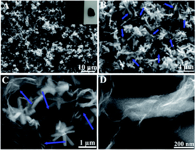 | ||
| Fig. 4 FESEM images of 3D H-NP-CoP NF/G IN at different magnifications. The inset in (A) is a photograph showing its large-scale structure. The arrows in (B) and (C) indicate graphene nanosheets. | ||
Fig. 5 displays the TEM and HRTEM images of the sample after phosphidation. The low-magnification TEM image (Fig. 5A) confirms the formation of CoP nanoflowers. Very interestingly, the high-magnification TEM images show that numerous pores are uniformly distributed throughout the petals (Fig. 5B), and their sizes range from 5 to 10 nm (Fig. 5C). The high-resolution TEM (HRTEM) image (Fig. 5D) reveals a lattice fringe with an interplane spacing of 0.281 nm, which corresponds to the (011) planes of orthorhombic CoP (JCPDS card no. 29-0497).2,50 The very slight deviation of this spacing from the standard one (0.283 nm) could be ascribed to the experimental errors from the measurement and/or TEM equipment calibration.
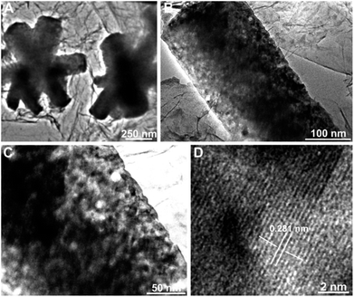 | ||
| Fig. 5 TEM images of 3D H-NP-CoP NF/G IN at different magnifications (A–C) and HRTEM image of 3D H-NP-CoP NF/G IN (D). | ||
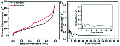
Fig. 6A shows the N2 adsorption–desorption isotherm of 3D H-NP-CoP NF/G IN. It exhibits type IV characteristics with a pronounced hysteresis at medium relative pressure between adsorption and desorption branches, suggesting that there are a number of mesopores in this sample.2,51 The pore size distribution obtained by the BJH method (Fig. 6B) further confirms the existence of mesopores with sizes of ∼2.8, 4.7, and 8.6 nm. As a comparison, pristine graphene only shows mesopores with a size of ∼3.2 nm (Fig. S1†). Therefore, the pore sizes of 4.7 and 8.6 nm could probably come from the CoP nanostructures, indicating the nanoporous structure of CoP.
To explore the possible mechanism of the self-assembly of the 3D H-NP-CoP NFs/G network, the synthesis was carried out without DETA. The FESEM results (Fig. 7A) show the formation of large particles with irregular shapes, and no nanoflowers or nanorods can be observed. The loading of particles is much lower than that of CoP nanoflowers formed via the DETA-mediated self-assembly. The graphene nanosheets are also aggregated without forming homogeneous mixtures with CoP particles. It is noteworthy that the XRD patterns of the samples both before and after phosphidation show the characteristic peaks of rhombohedral CoCO3 (JCPDS card no. 11-0692),52,53 and no peaks from CoP are observed for the sample after phosphidation (Fig. 7A inset), indicating a low degree of phosphidation (XPS results show that there is indeed some CoP formed, see Fig. S2†). The synthesis was also performed without graphene to investigate the possible self-assembly mechanism. The obtained particles are quite large and severely aggregated; they also exhibit an irregular shape, and none of them are nanoflowers or nanorods (Fig. 7B). The XRD patterns again show that the product before phosphidation is rhombohedral CoCO3 and little CoP has been formed after phosphidation (Fig. 7B inset).52,53 The concentration of Co(NO3)2 was further tuned to investigate the self-assembly mechanism. When the amount of Co(NO3)2·6H2O added in the reaction solution (volume kept at 30 mL) is lower than 0.5 g, no nanostructures are produced (see Fig. S3† for the FESEM image of the sample obtained with 0.5 g Co(NO3)2). With increasing the amount to 0.9 g, nanorods are formed but only very few of them are assembled into nanoflowers (Fig. 7C). Interestingly, when further increasing this amount to 1.0 g and above, almost all the nanorods obtained are in the form of nanoflowers, and their loading in the hybrid significantly increases (see Fig. 4 for the FESEM images of the sample obtained with 1.0 g Co(NO3)2·6H2O and Fig. 7D for that obtained with 1.2 g Co(NO3)2·6H2O). The XRD results show that the samples before and after phosphidation are orthorhombic Co(OH)F and orthorhombic CoP, respectively, for all the samples obtained with 0.9, 1.0 g, and 1.2 g of Co(NO3)2·6H2O (Fig. 7C inset, Fig. 3A and 7D inset).1,2,48,49
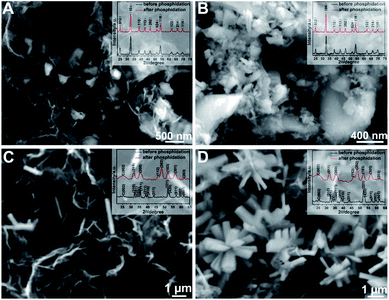 | ||
| Fig. 7 FESEM images of the samples synthesized without the addition of DETA (A), without the addition of graphene (B), with 0.9 g Co(NO3)2·6H2O (C), and with 1.2 g Co(NO3)2·6H2O (D). | ||
DETA has high affinity to both graphene and Co2+ due to the charge-transfer interaction and coordination bonding, respectively.46,47 Therefore, it can not only greatly promote the dispersion of graphene, but also facilitate the nucleation of CoP precursors on graphene and the growth of uniform nanostructures for in situ self-assembly of the 3D interconnected network. The low loading and large CoP precursor particles and aggregated graphene obtained without the addition of DETA can be ascribed to the nucleation occurring in solution rather than on graphene. The importance of in situ nucleation on graphene is also reflected by the formation of large and aggregated CoP precursor structures even when using DETA as the stabilizer when no graphene is added in the reaction system. Two competing reaction processes ((1), (2), and (3a) or (1), (2) and (3b)) could occur under the hydrothermal conditions:52,54
| H2NCONH2 + 3H2O → 2NH4+ + CO2 + 2OH− | (1) |
| CO2 + 2OH− → CO32− + H2O | (2) |
| Co2+ + OH− + F− → Co(OH)F | (3a) |
| Co2+ + CO32− → CoCO3 | (3b) |
Since Co2+ interacts more strongly with CO32− than with F− in solution, the solution-based nucleation under the synthesis conditions without DETA or graphene will favor the reaction of (3b) to produce CoCO3.54,55 This is in sharp contrast with the formation of Co(OH)F during the DETA mediated self-assembly with graphene. This result suggests that the nucleation of Co(OH)F on graphene via reaction (3a) is energetically more favorable than that of CoCO3via reaction (3b). It has been well recognized that Co(OH)F has a growth habit to form nanorods.54,56,57 That's why nanorod-based structures are obtained in our synthesis (Fig. 4C and Fig. 7C and D). The strong dependence of nanoflower creation on the concentration of Co2+ suggests that the high concentration of Co2+ could significantly enhance the nucleation rate, thus leading to the aggregation of seeds before the growth of nanorods.20,58 Therefore, it is very likely that the simultaneous nucleation of Co(OH)F seeds on highly dispersed graphene and the aggregation of these seeds result in the formation of an interconnected 3D network of H-Co(OH)F NF/G.
The low-temperature conversion of Co(OH)F to CoP is likely to occur according to the following reaction steps:
| 2NaH2PO2 → PH3 + Na2HPO4 | (4) |
| 2Co(OH)F + 2PH3 → 2CoP + 2H2O + 2HF + H2 | (5) |
During the phosphidation process, Co(OH)F is reduced to Co by PH3 released from NaH2PO2via thermal decomposition,59 and then the Co-catalyzed decomposition of PH3 produces P, which further reacts with Co to form CoP.60 The nanopores in the sample after phosphidation could be caused by the release of gases produced during these reactions.48,50 The much less phosphidation of CoCO3 is very likely due to the combination of the more difficult reduction of Co2+ in CoCO3 than in Co(OH)F arising from the stronger interaction between Co2+ and CO32− than between Co2+ and OH−/F− and the larger size of CoCO3 than Co(OH)F (Fig. 7A inset and Fig. 7B inset), leading to the production of less Co and thus less decomposition to form less P.54,55
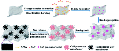
Based on the above experimental results and analysis, the possible mechanism of DETA-mediated self-assembly of 3D H-NP-CoP NF/G IN could be proposed (Fig. 8): firstly, DETA significantly improves the dispersion of graphene and promotes the nucleation of CoP precursors on graphene; secondly, the in situ nucleation on graphene favors the formation of Co(OH)F, which has a growth habit to form nanorods; thirdly, the high concentration of Co2+ greatly enhances the nucleation of Co(OH)F, and thus promotes the aggregation of seeds before the growth of nanorods, leading to the formation of Co(OH)F nanoflowers; fourthly, the aggregation of Co(OH)F seeds on highly dispersed graphene promotes the formation of a 3D interconnected network of H-Co(OH)F NF/G; lastly, the gas release occurring during the low-temperature phosphidation introduces nanopores into the CoP nanoflowers.
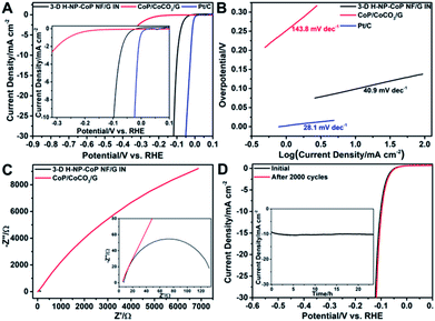
The catalytic performance of 3D H-NP-CoP NFs/G IN toward the HER was then investigated. Fig. 9A shows the linear sweep voltammetry (LSV) curve of 3D H-NP-CoP NFs/G IN. To reveal the effect of DETA-mediated self-assembly on the HER activity, the sample obtained without the addition of DETA (denoted as CoP/CoCO3/G) was also tested as a catalyst for the HER. In addition, the curve of commercial Pt/C is displayed to demonstrate the great potential of 3D H-NP-CoP NFs/G IN for practical applications. As expected, the commercial Pt/C catalyst shows excellent HER activity with an overpotential close to zero. Interestingly, 3D H-NP-CoP NFs/G IN exhibits very high catalytic activity as well. Its onset overpotential is only 14 mV, and it only requires an overpotential of 98.1 mV to achieve a current density of 10 mA cm−2, both of which are among the lowest reported for non-noble-metal HER catalysts (see Table 1 for a detailed comparison of reported most active non-noble-metal HER catalysts). The LSV result was further confirmed using a graphite rod as the counter electrode, showing a negligible change of the performance (Fig. S4†). In contrast, CoP/CoCO3/G has an onset overpotential of 160.4 mV, which is much larger than that of 3D H-NP-CoP NFs/G IN, and even the overpotential of 3D H-NP-CoP NFs/G IN to achieve 10 mA cm−2. This result demonstrates the unique advantages of DETA-mediated self-assembly of CoP with pristine graphene for greatly promoting the catalytic activity toward the HER.
| Catalyst | Loading (mg cm−2) | Onset potential (V) | Overpotential at 10 mA cm−2 (mV) | Tafel slope (mV dec−1) | Exchange current density (mA cm−2) | Reference |
|---|---|---|---|---|---|---|
| CoP/GA | 0.28 | −0.028 | 121 | 50 | 0.105 | 62 |
| CoxP | 0.56 | −0.03 | 144 | 58 | 63 | |
| ZIF-67-derived CoP/rGO-400 | 0.28 | −0.013 | 105 | 50 | 64 | |
| CoP/CNT | 0.285 | −0.04 | 122 | 54 | 0.13 | 61 |
| CoP hollow polyhedron | 0.102 | −0.035 | 159 | 59 | 0.037 | 65 |
| CoP/RGO | 0.285 | −0.1189 | 156.89 | 70.22 | 0.057 | 66 |
| CoP nanotubes | 0.2 | 129 | 60 | 67 | ||
| CoP/CC | 0.92 | −0.038 | 67 | 51 | 0.288 | 50 |
| CoP-ordered mesoporous carbon | 0.285 | −0.0777 | 112.18 | 56.67 | 0.161 | 66 |
| CoP nanowires | 0.35 | −0.04 | 110 | 54 | 0.16 | 68 |
| CoP/BMHNC | 0.3 | −0.007 | 95.8 | 33 | 0.1182 | 2 |
| NiCoP nanoparticles/Ti | 0.75 | −0.042 | 97 | 50 | 69 | |
| Hollow Ni2P nanoparticles | 1 | 116 | 46 | 0.033 | 70 | |
| Ni5P4–Ni2P nanosheet array | −0.054 | 120 | 79.1 | 0.116 | 71 | |
| Ni2P/NRGO | 0.2 | −0.037 | 102 | 59 | 0.049 | 72 |
| Nanoporous FeP nanosheets | 0.28 | −0.1 | 240 | 67 | 73 | |
| FeP/graphene nanosheets | 0.28 | −0.03 | 123 | 50 | 0.12 | 74 |
| MoS2/RGO | 1 | −0.1 | 41 | 75 | ||
| MoC–Mo2C | 0.14 | −0.038 | 126 | 43 | 0.011 | 76 |
| FeP NPs@NPC | 1.4 | 130 | 67 | 0.126 | 77 | |
| 3D H-NP-CoP NF/G IN | 0.35 | −0.014 | 98.1 | 40.9 | 0.119 | This work |
Fig. 9B displays the Tafel plots of 3D H-NP-CoP NFs/G IN, CoP/CoCO3/G, and commercial Pt/C. The Tafel slope of Pt/C is 28.1 mV dec−1, close to the reported values.1,2,61 3D H-NP-CoPNFs/G IN has a Tafel slope of 40.9 mV dec−1, which compares favorably to those of most reported non-noble-metal HER catalysts (Table 1). Although the Tafel slope does not match the expected values of 29, 38, and 116 mV dec−1 corresponding to different rate-determining steps in the HER, this result clearly shows very fast kinetics of the HER on 3D H-NP-CoP NFs/G IN. In comparison, the Tafel slope of CoP/CoCO3/G is 143.8 mV dec−1, indicating its much slower HER rate. The exchange current density of 3D H-NP-CoP NFs/G IN is achieved to be 0.119 mA cm−2, which is at the same magnitude as that of Pt/C (0.794 mA cm−2). This exchange current density is also higher than those of most reported non-noble-metal based HER catalysts (Table 1). However, the exchange current density of CoP/CoCO3/G is only 0.0178 mA cm−2. Therefore, its intrinsic catalytic activity is much poorer than that of 3D H-NP-CoP NFs/G IN.
The superior HER catalytic activity of 3D H-NP-CoP NFs/G IN could be ascribed to several reasons: (i) the larger nanoflower structures greatly facilitate the diffusion of reactants and products and the smaller nanorods with high-density nanopores provide a large surface area for numerous catalytically active sites;23,36,37 (ii) the 3D interconnected nanostructure offers a large number of open pores for further enhancing the mass diffusion;15,18 (iii) the excellent conductivity of pristine graphene and nanorod-composed CoP nanoflowers promotes the formation of a 3D conducting network for fast charge transport;27,44,78 (iv) the high intrinsic OER activity of CoP and its 3D intimate contact with highly conductive pristine graphene significantly improve the reaction kinetics.79,80
Electrochemical impedance spectroscopy (EIS) was performed to investigate the interfacial charge transfer during the HER. Indeed, 3D H-NP-CoP NFs/G IN has a much lower charge transfer resistance than CoP/CoCO3/G, indicating that the DETA-mediated self-assembly can greatly facilitate the electron transfer between the in situ grown CoP nanorod-composed nanoflowers and the pristine graphene (Fig. 9C). A smaller charge transfer resistance corresponds to faster reaction kinetics, and thus this result further confirms the much more favorable HER kinetics of 3D H-NP-CoP NFs/G IN than those of CoP/CoCO3/G.
The durability of an electrocatalyst is very critical for its practical application. Fig. 9D shows the LSV curves of 3D H-NP-CoP NFs/G IN measured before and after 2000 cyclic voltammetry (CV) cycles ranging from 0.01 to −0.17 V versus the RHE at a scan rate of 100 mV s−1. The LSV curve after the CV experiment exhibits negligible loss in current density compared with the initial one. The inset in Fig. 9D illustrates the time dependence of the current density at an overpotential of 98.1 mV, revealing that 3D H-NP-CoP NFs/G IN can maintain its catalytic activity for at least 23.5 h.
The amount of hydrogen produced through electrochemical water splitting was measured quantitatively using gas chromatography (GC). The faradaic efficiency (FE) of the HER process can be obtained by dividing the measured amount of hydrogen with the calculated one (assuming 100% FE). The excellent agreement of the two sets of values (Fig. S5†) indicates that the FE is close to 100%.
Conclusions
A novel 3D hierarchical nanoporous CoP nanoflowers/pristine graphene interconnected network structure has been synthesized via DETA-mediated self-assembly, in which DETA promotes the uniform dispersion of graphene and the nucleation of the CoP precursor on graphene, the seed aggregation facilitates the formation of nanoflowers and a 3D network, and the gas release during the low-temperature phosphidation produces nanopores inside the nanoflowers. This nanoarchitecture shows an onset potential of −0.014 V, an overpotential of 98.1 mV to achieve 10 mA cm−2, a Tafel slope of 40.9 mV dec−1, and an exchange current density of 0.119 mA cm−2, all of which compare favorably to those of most reported HER catalysts. In addition, the catalyst exhibits excellent durability with negligible loss in current density after 2000 cyclic voltammetry (CV) cycles (+0.01 to −0.17 V vs. the RHE, at a scan rate of 100 mV s−1) or 23.5 h of chronoamperometric measurement at an overpotential of 98.1 mV, and a high faradaic efficiency of close to 100%. This work not only creates a high-performance and inexpensive HER electrocatalyst by taking advantage of a unique 3D hierarchically nanostructured network but also develops a facile and economical strategy for the self-assembly of hierarchical nanostructures and provides scientific insight into its mechanism.Conflicts of interest
There are no conflicts to declare.Acknowledgements
This work was financially supported by the Scientific Research Foundation for the Returned Overseas Chinese Scholars, Ministry of Education of China, Chongqing Natural Science Foundation (No. cstc2015jcyjA50029), the Fundamental Research Funds for the Central Universities (Grant No. XDJK2017B057), and the Start-up grant from Southwest University, China (Grant No. SWU114090), and the Program for Innovation Team Building at Institutions of Higher Education in Chongqing (CXTDX201601011).Notes and references
- X. Wang, W. Yuan, Y. Yu and C. M. Li, ChemSusChem, 2017, 10, 1014–1021 CrossRef CAS PubMed.
- W. Yuan, X. Wang, X. Zhong and C. M. Li, ACS Appl. Mater. Interfaces, 2016, 8, 20720–20729 CAS.
- W. Tang, Y. Han, C. B. Han, C. Z. Gao, X. Cao and Z. L. Wang, Adv. Mater., 2015, 27, 272–276 CrossRef CAS PubMed.
- L. Z. Wu, B. Chen, Z. J. Li and C. H. Tung, Acc. Chem. Res., 2014, 47, 2177–2185 CrossRef CAS PubMed.
- Z. W. Seh, J. Kibsgaard, C. F. Dickens, I. Chorkendorff, J. K. Nørskov and T. F. Jaramillo, Science, 2017, 355, 1–12 CrossRef PubMed.
- J. Wang, F. Xu, H. Jin, Y. Chen and Y. Wang, Adv. Mater., 2017, 29, 1605838 CrossRef PubMed.
- Y. Shi and B. Zhang, Chem. Soc. Rev., 2016, 45, 1529–1541 RSC.
- J. R. McKone, S. C. Marinescu, B. S. Brunschwig, J. R. Winkler and H. B. Gray, Chem. Sci., 2014, 5, 865–878 RSC.
- J. R. McKone, B. F. Sadtler, C. A. Werlang, N. S. Lewis and H. B. Gray, ACS Catal., 2013, 3, 166–169 CrossRef CAS.
- C. G. Morales-Guio, L. A. Stern and X. Hu, Chem. Soc. Rev., 2014, 43, 6555–6569 RSC.
- T. Liu, D. Liu, F. Qu, D. Wang, L. Zhang, R. Ge, S. Hao, Y. Ma, G. Du, A. M. Asiri, L. Chen and X. Sun, Adv. Energy Mater., 2017, 7, 1700020 CrossRef.
- C. Tang, L. Gan, R. Zhang, W. Lu, X. Jiang, A. M. Asiri, X. Sun, J. Wang and L. Chen, Nano Lett., 2016, 16, 6617–6621 CrossRef CAS PubMed.
- M. Ma, G. Zhu, F. Xie, F. Qu, Z. Liu, G. Du, A. M. Asiri, Y. Yao and X. Sun, ChemSusChem, 2017, 10, 3188–3192 CrossRef CAS PubMed.
- T. Liu, L. Xie, J. Yang, R. Kong, G. Du, A. M. Asiri, X. Sun and L. Chen, ChemElectroChem, 2017, 4, 1840–1845 CrossRef CAS.
- H. Zhu, L. Gu, D. Yu, Y. Sun, M. Wan, M. Zhang, L. Wang, L. Wang, W. Wu, J. Yao, M. Du and S. Guo, Energy Environ. Sci., 2017, 10, 321–330 CAS.
- W. Li, S. Zhang, Q. Fan, F. Zhang and S. Xu, Nanoscale, 2017, 9, 5677–5685 RSC.
- W. Yuan and C. M. Li, Chem. Commun., 2010, 46, 9161–9163 RSC.
- W. Yuan, M. Zhao, J. Yuan and C. M. Li, J. Power Sources, 2016, 319, 159–167 CrossRef CAS.
- M. R. Lukatskaya, B. Dunn and Y. Gogotsi, Nat. Commun., 2016, 7, 12647 CrossRef PubMed.
- W. Yuan, Z. Lu and C. M. Li, J. Mater. Chem. A, 2013, 1, 6416–6424 CAS.
- Q. Ji, M. Miyahara, J. P. Hill, S. Acharya, A. Vinu, S. B. Yoon, J.-S. Yu, K. Sakamoto and K. Ariga, J. Am. Chem. Soc., 2008, 130, 2376–2377 CrossRef CAS PubMed.
- K. J. M. Bishop, C. E. Wilmer, S. Soh and B. A. Grzybowski, Small, 2009, 5, 1600–1630 CrossRef CAS PubMed.
- J. H. Bahng, B. Yeom, Y. Wang, S. O. Tung, J. D. Hoff and N. Kotov, Nature, 2015, 517, 596–599 CrossRef CAS PubMed.
- M. A. Boles, M. Engel and D. V. Talapin, Chem. Rev., 2016, 116, 11220–11289 CrossRef CAS PubMed.
- J.-Y. Kim and N. A. Kotov, Chem. Mater., 2014, 26, 134–152 CrossRef CAS.
- Q. Li, N. Mahmood, J. Zhu, Y. Hou and S. Sun, Nano Today, 2014, 9, 668–683 CrossRef CAS.
- A. K. Geim, Science, 2009, 324, 1530–1534 CrossRef CAS PubMed.
- X. Zhuang, Y. Mai, D. Wu, F. Zhang and X. Feng, Adv. Mater., 2015, 27, 403–427 CrossRef CAS PubMed.
- W. Yuan, X. Fan, Z. M. Cui, T. Chen, Z. Dong and C. M. Li, J. Mater. Chem. A, 2016, 4, 7352–7364 CAS.
- S. Eigler and A. Hirsch, Angew. Chem., Int. Ed., 2014, 53, 7720–7738 CrossRef CAS PubMed.
- H. Wang, H. S. Casalongue, Y. Liang and H. Dai, J. Am. Chem. Soc., 2010, 132, 7472–7477 CrossRef CAS PubMed.
- Y. Liang, Y. Li, H. Wang and H. Dai, J. Am. Chem. Soc., 2013, 135, 2013–2036 CrossRef CAS PubMed.
- Q. Shi, Y. Cha, Y. Song, J.-I. Lee, C. Zhu, X. Li, M.-K. Song, D. Du and Y. Lin, Nanoscale, 2016, 8, 15414–15447 RSC.
- H.-K. Kim, S.-H. Park, S.-B. Yoon, C.-W. Lee, J. H. Jeong, K. C. Roh and K.-B. Kim, Chem. Mater., 2014, 26, 4838–4843 CrossRef CAS.
- S. Mann, Nat. Mater., 2009, 8, 781–792 CrossRef CAS PubMed.
- Z. Nie, A. Petukhova and E. Kumacheva, Nat. Nanotechnol., 2010, 5, 15–25 CrossRef CAS PubMed.
- W. Yuan, Z. Lu, H. Wang and C. M. Li, Adv. Funct. Mater., 2012, 22, 1932–1939 CrossRef CAS.
- W. Yuan, P. K. Shen and S. P. Jiang, J. Mater. Chem., A, 2014, 2, 123–129 CAS.
- H.-B. Yao, M.-R. Gao and S.-H. Yu, Nanoscale, 2010, 2, 322–334 Search PubMed.
- A. Zabet-Khosousi and A.-A. Dhirani, Chem. Rev., 2008, 108, 4072–4124 CrossRef CAS PubMed.
- K. Tao, A. Levin, L. Adler-Abramovich and E. Gazit, Chem. Soc. Rev., 2016, 45, 3935–3953 RSC.
- W. M. Park and J. A. Champion, ACS Nano, 2016, 10, 8271–8280 CrossRef CAS PubMed.
- H. Xu, X. Hu, H. Yang, Y. Sun, C. Hu and Y. Huang, Adv. Energy Mater., 2015, 5, 1401882 CrossRef.
- K. V. Kumar, K. Preuss, M.-M. Titirici and F. Rodríguez-Reinoso, Chem. Rev., 2017, 117, 1796–1825 CrossRef CAS PubMed.
- K. A. Cychosz, R. Guillet-Nicolas, J. Garcia-Martinez and M. Thommes, Chem. Soc. Rev., 2017, 46, 389–414 RSC.
- Y. Kim, J. Ryu, M. Park, E. S. Kim, J. M. Yoo, J. Park, J. H. Kang and B. H. Hong, ACS Nano, 2014, 8, 868–874 CrossRef CAS PubMed.
- Y. Kim, J. Park, J. Kang, J. M. Yoo, K. Choi, E. S. Kim, J.-B. Choi, C. Hwang, K. S. Novoselov and B. H. Hong, Nanoscale, 2014, 6, 9545–9549 RSC.
- L. Li, K. H. Seng, Z. Chen, Z. Guo and H. K. Liu, Nanoscale, 2013, 5, 1922–1928 RSC.
- S. Ni, J. Ma, J. Zhang, X. Yang and L. Zhang, Mater. Lett., 2015, 139, 138–140 CrossRef CAS.
- J. Tian, Q. Liu, A. M. Asiri and X. Sun, J. Am. Chem. Soc., 2014, 136, 7587–7590 CrossRef CAS PubMed.
- Z. Xing, Z. Ju, Y. Zhao, J. Wan, Y. Zhu, Y. Qiang and Y. Qian, Sci. Rep., 2016, 6, 26146 CrossRef CAS PubMed.
- C. C. Li, X. M. Yin, T. H. Wang and H. C. Zeng, Chem. Mater., 2009, 21, 4984–4992 CrossRef CAS.
- H.-P. Cong and S.-H. Yu, Cryst. Growth Des., 2009, 9, 210–217 CAS.
- Z. Wen, L. Zhu, W. Mei, Y. Li, L. Hu, L. Sun, W. Wan and Z. Ye, J. Mater. Chem., A, 2013, 1, 7511–7518 CAS.
- L. Zhu, Z. Wen, W. Mei, Y. Li and Z. Ye, J. Phys. Chem. C, 2013, 117, 20465–20473 CAS.
- Y.-X. Zhang, X. Guo, X. Zhai, Y.-M. Yan and K.-N. Sun, J. Mater. Chem., A, 2015, 3, 1761–1768 CAS.
- W. Mei, J. Huang, L. Zhu, Z. Ye, Y. Mai and J. Tu, J. Mater. Chem., 2012, 22, 9315–9321 RSC.
- M. Mo, J. C. Yu, L. Zhang and S. K. A. Li, Adv. Mater., 2005, 17, 756–760 CrossRef CAS.
- Q. Guan and W. Li, J. Catal., 2010, 271, 413–415 CrossRef CAS.
- X. J. Tang, Z. M. Xiu, C. X. Han and B. G. Zhang, in Sustainable Nanotechnology and the Environment: Advances and Achievements, American Chemical Society, Washington, 2013, vol. 1124, pp. 181–199 Search PubMed.
- Q. Liu, J. Tian, W. Cui, P. Jiang, N. Cheng, A. M. Asiri and X. Sun, Angew. Chem., Int. Ed., 2014, 53, 6710–6714 CrossRef CAS PubMed.
- X. Zhang, Y. Han, L. Huang and S. Dong, ChemSusChem, 2016, 9, 3049–3053 CrossRef CAS PubMed.
- L. Tian, X. Yan, X. Chen, L. Liu and X. Chen, J. Mater. Chem., A, 2016, 4, 13011–13016 CAS.
- L. Jiao, Y.-X. Zhou and H.-L. Jiang, Chem. Sci., 2016, 7, 1690–1695 RSC.
- M. Liu and J. Li, ACS Appl. Mater. Interfaces, 2016, 8, 2158–2165 CAS.
- M. Li, X. Liu, Y. Xiong, X. Bo, Y. Zhang, C. Han and L. Guo, J. Mater. Chem., A, 2015, 3, 4255–4265 CAS.
- H. Du, Q. Liu, N. Cheng, A. M. Asiri, X. Sun and C. M. Li, J. Mater. Chem., A, 2014, 2, 14812–14816 CAS.
- P. Jiang, Q. Liu, C. Ge, W. Cui, Z. Pu, A. M. Asiri and X. Sun, J. Mater. Chem., A, 2014, 2, 14634–14640 CAS.
- C. Wang, J. Jiang, T. Ding, G. Chen, W. Xu and Q. Yang, Adv. Mater. Interfaces, 2016, 3, 1500454 CrossRef.
- E. J. Popczun, J. R. McKone, C. G. Read, A. J. Biacchi, A. M. Wiltrout, N. S. Lewis and R. E. Schaak, J. Am. Chem. Soc., 2013, 135, 9267–9270 CrossRef CAS PubMed.
- X. Wang, Y. V. Kolen'ko, X.-Q. Bao, K. Kovnir and L. Liu, Angew. Chem., Int. Ed., 2015, 54, 8188–8192 CrossRef CAS PubMed.
- Y. Pan, N. Yang, Y. Chen, Y. Lin, Y. Li, Y. Liu and C. Liu, J. Power Sources, 2015, 297, 45–52 CrossRef CAS.
- Y. Xu, R. Wu, J. Zhang, Y. Shi and B. Zhang, Chem. Commun., 2013, 49, 6656–6658 RSC.
- Z. Zhang, B. Lu, J. Hao, W. Yang and J. Tang, Chem. Commun., 2014, 50, 11554–11557 RSC.
- Y. Li, H. Wang, L. Xie, Y. Liang, G. Hong and H. Dai, J. Am. Chem. Soc., 2011, 133, 7296–7299 CrossRef CAS PubMed.
- H. Lin, Z. Shi, S. He, X. Yu, S. Wang, Q. Gao and Y. Tang, Chem. Sci., 2016, 7, 3399–3405 RSC.
- Z. Pu, I. S. Amiinu, C. Zhang, M. Wang, Z. Kou and S. Mu, Nanoscale, 2017, 9, 3555–3560 RSC.
- S. Carenco, D. Portehault, C. Boissière, N. Mézailles and C. Sanchez, Chem. Rev., 2013, 113, 7981–8065 CrossRef CAS PubMed.
- G. Hu, Q. Tang and D.-e. Jiang, Phys. Chem. Chem. Phys., 2016, 18, 23864–23871 RSC.
- Y. Pan, Y. Lin, Y. Chen, Y. Liu and C. Liu, J. Mater. Chem. A, 2016, 4, 4745–4754 CAS.
Footnote |
| † Electronic supplementary information (ESI) available: High-resolution Co 2p3/2 and P 2p XPS spectra of CoP/CoCO3/G; FESEM image of the sample synthesized with 0.5 g Co(NO3)2·6H2O; calculated and measured amount of hydrogen at different times for CoP/BMHNC at −0.15 V for 120 min in 0.5 M H2SO4. See DOI: 10.1039/c7se00454k |
| This journal is © The Royal Society of Chemistry 2017 |

