Higher efficiency perovskite solar cells using additives of LiI, LiTFSI and BMImI in the PbI2 precursor†
Sally
Mabrouk
a,
Behzad
Bahrami
a,
Ashim
Gurung
a,
Khan Mamun
Reza
a,
Nirmal
Adhikari
a,
Ashish
Dubey
a,
Rajesh
Pathak
a,
Shangfeng
Yang
 b and
Qiquan
Qiao
 *a
*a
aCenter for Advanced Photovoltaics, Department of Electrical Engineering and Computer Science, South Dakota State University, Brookings, SD 57007, USA. E-mail: Qiquan.Qiao@sdstate.edu; Fax: +1-605-688-4401; Tel: +1-605-688-6965
bHefei National Laboratory for Physical Sciences at Microscale, Key Laboratory of Materials for Energy Conversion, Chinese Academy of Sciences, Department of Materials Science and Engineering, Synergetic Innovation Center of Quantum Information & Quantum Physics, University of Science and Technology of China (USTC), Hefei 230026, China
First published on 3rd October 2017
Abstract
The efficiencies of perovskite solar cells have been significantly increased to 18%, 17.01% and 15.6% for the cells containing the additives BMImI, LiI and LiTFSI in the PbI2 precursor solutions, respectively, from 11.3% for the devices without any additives. Incorporation of these additives led to the formation of perovskites with larger grain size and higher crystallinity with reduced PbI2 residue as indicated by X-ray diffraction (XRD) and atomic force microscopy (AFM) results. Kelvin Probe Force Microscopy (KPFM) and current sensing (CS)-AFM results were in good agreement with external quantum efficiency (EQE) measurements and proved the great enhancement in short circuit current density (Jsc) as a result of doping. Transient photovoltage measurement results exhibited longer charge carrier lifetimes for the additive incorporated perovskites than those without additives, thus improving the fill factor (FF) and open circuit voltage (Voc). In addition to the improved efficiency, the incorporation of these additives led to higher stability of the CH3NH3PbI3 perovskite solar cells. The new additive BMImI, LiI and LiTFSI incorporated CH3NH3PbI3 perovskite solar cells exhibited a reduced degradation with a 57%, 60%, and 91% decrease in performance respectively after exposure to air for 70 days compared to a 93% decrease for the pristine cell after only 24 days. The lithium salt additives can serve as desiccants to absorb moisture preventing perovskite degradation. Further, the BMImI additive can prevent the formation of free radicals in perovskites upon exposure to light and heat.
Introduction
Crystalline silicon solar cells dominate the photovoltaic industry with a relatively expensive manufacturing process. Attempts are being made to fabricate devices from low cost materials and simple solution processing without annealing at high temperature. Perovskites have become prospective materials for achieving optimum performance for photovoltaic (PV) technology. Organometal halide perovskite (AMX3, X = halides) materials demonstrate excellent optical properties that are tunable by managing chemical compositions,1 ambipolar charge transport,2 and long electron hole diffusion lengths.3–5The first perovskite solar cell was prepared by Miyasaka et al. using the same structure of dye-sensitized solar cells, and the dye was exchanged with lead halide perovskite as a light absorber/sensitizer, achieving a very low efficiency of 3.81%.6 Since then, different perovskite film preparation and crystallization methods have been reported7–14 including vapor-assisted solution processing (VASP), physical vapor deposition (PVD), and single step and sequential deposition methods.1,2,7,15,16 n–i–p structure perovskite solar cells, in which the n-layer is mesoporous titanium dioxide (TiO2), the intrinsic (i) layer is a light absorber (CH3NH3PbI3) and the p-layer is spiro-OMeTAD achieved an efficiency up to 10% in 2012 by replacing liquid electrolytes with an organic hole transport material spiro-OMeTAD.17 Then in 2014, Yang et al. optimized the environmental humidity while fabricating perovskite solar cells and achieved an efficiency up to 19.3%.18 Recently, perovskite solar cells have achieved power conversion efficiencies higher than 20% (ref. 19) and outperformed other solar cells based on DSSCs,20 small molecules21 and polymer solar cells.22–25
The morphology of perovskite films plays an important role in device performance.26,27 The perovskite morphology and grain size can be engineered using additives or post treatment. Zhang et al. used 4-tert-butylpyridine (TBP) as an additive in the PbI2 solution and obtained high quality films without pin holes in mesoporous structures.28 Other additives such as 1,8-diiodooctane (DIO), 1-chloronaphthalene (CN), ammonium chloride, MAI and hydrochloric acid have been used in the perovskite precursor solution to improve the perovskite film quality.29–32 A small amount of water was also used to improve the crystallization of the perovskite film. Adhikari et al. added an optimal amount of water to the MAI solution to increase the crystallization and grain size of the perovskite film.16 The doping of spiro-OMeTAD has been done using bis(trifluoromethane)sulfonimide lithium salt (LiTFSI) to increase the hole conductivity of the hole transport layer (HTL). However, it has not been used to increase the crystallinity of the perovskite film by doping PbI2 precursor for the formation of the perovskite film from the sequential deposition method. The doping of the PbI2 layer has been conducted by various groups to increase the surface coverage and uniformity of the perovskite film for efficient solar cells.16,33,34 Recently, our group reported the doping of the PbI2 layer with tetra-n-butylammonium triiodide (TBAI3) additive to enhance the efficiency of the CH3NH3PbI3 perovskite solar cell to 14.85% from 11.18% of the pristine cell and improve the stability showing an efficiency decrease of only 71% after exposure to air for 10 days versus a 92% decrease for the pristine cell. However, the long term stability of the TBAI3 doped perovskite was still poor with zero efficiency after 15 days.35
This work reports the incorporation of new additives such as BMImI, LiI and LiTFSI for doping the PbI2 layer with a much higher stability in air in addition to higher efficiency. The new additive BMImI, LiI and LiTFSI incorporated CH3NH3PbI3 perovskite solar cells exhibited a reduced degradation with a 57%, 60%, and 91% decrease in performance respectively after exposure to air for 70 days, which is a significant improvement over a 93% decrease for the pristine cell after only 24 days. An optimum concentration of 12 mg ml−1 of each of these additives led to complete conversion of CH3NH3I and PbI2 precursors into CH3NH3PbI3 perovskites. This demonstrated an improvement in efficiency to 18%, 17.01% and 15.6% for the BMImI, LiI and LiTFSI doped perovskites respectively versus 11.3% for the pristine perovskite.
Experimental procedures
Materials
Methylammonium iodide (CH3NH3I) and mesoporous TiO2 were purchased from Dyesol. Lead iodide (PbI2) was ordered from Acros organics. LiTFSI, LiI and BMImI were obtained from Sigma Aldrich. FTO coated glass substrates were purchased from Hartford Glass Company.Device fabrication
Perovskite solar cells were fabricated on fluorine doped tin dioxide (FTO) coated substrates (1.5 cm × 1.5 cm). FTO substrates were etched with diluted HCl solution (1 ml HCl in 10 ml DI water) and zinc powder. The etched substrates were then cleaned via sonication in soap water, DI-water, acetone and isopropanol for 25 min, respectively, followed by treatment with oxygen plasma.A thin layer of compact TiO2 (0.15 M titanium diisopropoxide in ethanol) was spin coated at 4500 rpm for 45 s followed by annealing at 200 °C for 10 min. A thin layer of mesoporous TiO2 scaffold (150–200 nm) was deposited by spin coating at 5000 rpm for 30 s using a commercial TiO2 paste (30 NRD, Dyesol) diluted in ethanol with a weight ratio of 1![[thin space (1/6-em)]](https://www.rsc.org/images/entities/char_2009.gif) :
:![[thin space (1/6-em)]](https://www.rsc.org/images/entities/char_2009.gif) 6 followed by annealing at 460 °C for 30 min. Substrates coated with TiO2 were immersed in 25 mM TiCl4 aqueous solution and annealed at 70 °C for 30 min followed by washing with DI water and ethanol, and then they were annealed at 460 °C for 30 min.
6 followed by annealing at 460 °C for 30 min. Substrates coated with TiO2 were immersed in 25 mM TiCl4 aqueous solution and annealed at 70 °C for 30 min followed by washing with DI water and ethanol, and then they were annealed at 460 °C for 30 min.
PbI2 (462 mg PbI2 + 12 mg additive per ml DMF) solutions with different additives (LiI, LiTFSI and BMImI) were prepared by stirring for 2 h on a hot plate at 70 °C inside a glovebox. PbI2 solutions were spin coated at 4000 rpm for 45 s followed by annealing at 70 °C for 30 min. They were then dip coated into a CH3NH3I (10 mg ml−1 isopropanol) solution for 1.5 min followed by immediately spin coating perovskite films at 6000 rpm for 10 s for drying. Finally, perovskite films were annealed at 100 °C for 15 min.
Spiro-OMeTAD was used as a hole transport layer. It was prepared by mixing 86 mg of (2,2′,7,7′-tetrakis(N,N-di-p-methoxyphenylamine)-9,9-spirobifluorene) (spiro-MeOTAD), 34 μl of 4-tert-butylpyridine, 19 μl of a stock solution of 520 mg ml−1 lithium bis-(trifluoromethylsulfonyl)imide in acetonitrile, and 12.5 μl of a stock solution of 50 mg tris(2-(1H-pyrazol-1-yl)-4-tert-butylpyridine)–cobalt(III) (FK209, Dynamo) dissolved in 0.2 ml chlorobenzene. Spiro-MeOTAD was spin coated outside the glove box on the top of the perovskite layer at 4000 rpm for 40 s. Samples were then transferred to an evaporator for Ag deposition (120 nm) as the top electrode.
Characterization
UV-vis absorption spectra of perovskite films were recorded using an Agilent 8453 UV-vis spectrophotometer. The perovskite thin films were characterized using a Rigaku Smartlab X-ray diffractometer (XRD). The topography of thin films was measured using an Agilent SPM 5500 atomic force microscope equipped with a MAC III controller (three lock-in amplifiers) and a tip with a resonance frequency of 67 kHz. The photocurrent density–voltage characteristics of the fabricated cells were measured using an Agilent 4155C under AM 1.5 illumination. CS-AFM is a technique for the nanoscale electrical characterization of materials with high spatial resolution. A conducting AFM tip was used to scan the sample surface in the contact mode and the current was measured when the probe comes into contact with conducting locations. The image of local variations of current (typically in the pA to nA range) is recorded simultaneously with the sample topography and presented as a current map. CS-AFM measurements were conducted in contact mode with a Pt/Ir coated Si tip. An Agilent 4155C semiconductor parameter analyzer was used to measure current density–voltage (J–V) curves under AM 1.5 illumination. An Agilent SPM 5500 atomic force microscope equipped with a MAC III controller (comprising three lock-in amplifiers) was used to map the surface potential of the TiO2 and perovskite films. KPFM is a non-contact atomic force microscopy method which uses a conducting tip as a Kelvin probe to measure the surface potential. It uses a feedback loop that adjusts the DC potential which nullifies the force component experienced in the tip, giving rise to a surface potential. The CPD between the tip and sample was measured together with topography. The tip was excited with an electrical oscillation that induces an electrostatic force between the tip and sample. This electrostatic force was nullified by applying the direct-voltage (dc) offset on the scanning tip at every pixel of the sample. This potential is actually the CPD between the tip and sample, which is their work function difference. A solar simulator (xenon lamp, Newport) was used as a light source with a light intensity of ∼100 mW cm−2. The light intensity was calibrated using a National Renewable Energy Laboratory (NREL) Si solar cell (S1133 14-01). The scan rate was 0.5 V s−1, and the scan direction was (from 0 to 1.1 V) and (from 1.1 to 0 V). The external quantum efficiency (EQE) was measured using a xenon lamp (Newport) attached to a monochromator (Newport). Two focusing lenses were used to focus the monochromatic light onto the active area of the solar cell. NREL calibrated photo-diodes were used as a reference for EQE measurements. Transient measurements were performed using an OBB's Model OL-4300 nitrogen laser (crisp pulse at 337 nm) to pump the model 1011 dye laser to generate a short pulse, which acted as an excitation source with a pulse duration of <1 ns and a repetition rate of ∼4 Hz.Results and discussion
Fig. 1 indicates the UV-vis spectra of perovskite films prepared under the same conditions of device fabrication from PbI2 solutions doped with LiTFSI, LiI and BMImI additives. The UV-vis spectra indicate a broad absorption band across the visible region with two significant peaks at 470 nm and 790 nm. The characteristic absorption shoulder near 740 nm for MAPbI3 perovskite increases with the addition of the additives where BMImI has the highest peak absorbance, followed by LiI and LiTFSI and no additive with the lowest peak absorbance. Absorbance is directly proportional to the external quantum efficiency (EQE) of the solar cells. The higher absorbance of the additive incorporated MAPbI3 perovskite is supported by the EQE data of the perovskite solar cells with the highest EQE percent for BMImI, followed by LiI and LiTFSI versus the lowest EQE percent for the no additive perovskite. The increase in the absorbance may have resulted from the generation of new energy levels after the addition of LiI, LiTFSI and BMImI additives. This decreases the bandgap of perovskite materials,36 which broadens their absorption spectrum range giving rise to a higher Jsc.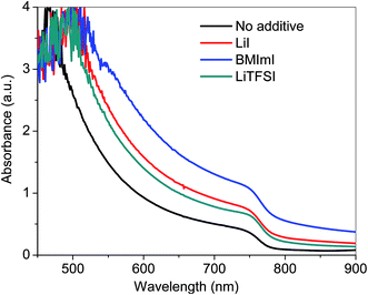 | ||
| Fig. 1 UV-vis absorption spectra of CH3NH3PbI3 films with and without the additives of LiI, LiTFSI and BMImI in the PbI2 layer. All films were deposited on the FTO/TiO2 substrate. | ||
Fig. 2 shows XRD measurements of perovskite films prepared by doping the PbI2 solution with an optimized concentration of additives LiI, LiTFSI and BMImI (12 mg/1 ml). The peaks at the 2-theta values of 14.08°, 28.41°, 31.85°, and 43.19° corresponding to the tetragonal crystal structure of halide perovskite are assigned to the (110), (220), (310), and (330) planes of CH3NH3PbI3, respectively.37,38 The peak at 12.12° is assigned to the (001) plane of PbI2 suggesting its incomplete conversion into perovskite. The incomplete conversion from precursor to perovskite has been previously reported in a sequential deposition method adopted for perovskite formation.9,38,39
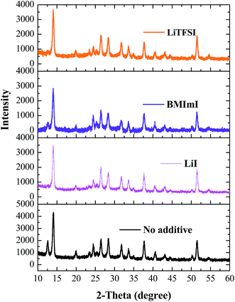 | ||
| Fig. 2 XRD spectra of FTO/TiO2/CH3NH3PbI3 films before and after adding additives LiI, LiTFSI and BMImI into the PbI2 layer. | ||
Adding LiI, BMImI and LiTFSI to the PbI2 layer leads to the disappearance of the peak at 12.12° compared to the perovskite film without adding additives. This suggests that a complete conversion of PbI2 into perovskite has occurred while adding the above dopants into the PbI2 precursor. This was attributed to polar additives which acted as polar Lewis bases that donate electrons to the Lewis acid Pb2+ in the PbI2. This produced the Lewis base adduct of PbI2 and increased the solubility of PbI2. The enhanced solubility due to additives leads to the formation of a much smoother PbI2 film compared to the undoped film. The same amount of time was used for the dip-coating of the spin-coated PbI2 film into the MAI solution. Since the doped MAPbI3 film had no dominant PbI2 peaks as observed in undoped MAPbI3, this implies that the reaction time between doped PbI2 and MAI was lower versus the undoped PbI2 indicating the enhancement in the reaction between the two. Thus the amount of PbI2 residue was reduced and the perovskite crystallinity was enhanced.35,36
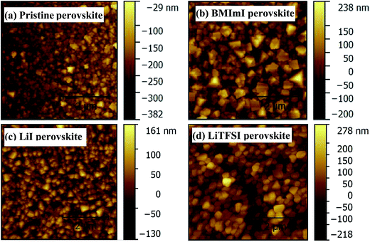
AFM topography images (Fig. 3) show that adding lithium and imidazolium iodide derivatives into the PbI2 layer increased the crystal size. Perovskite films where the precursor PbI2 layer was doped with LiI, BMImI and LiTFSI have a larger crystal size than that without any additives especially in the case of the BMImI dopant. The increased perovskite crystal size is in good agreement with XRD patterns as the crystal growth is highly regulated by the formation of the adducts of MAI, PbI2 and the dopants which act as polar Lewis bases. This adduct formation increased the solubility of PbI2 and enhanced its reaction with methylamine iodide, and thus enhanced crystal growth resulting in perovskite films with larger crystal size for higher crystallization.35,36 The crystal growth follows the order of BMImI > LiTFSI > LiI. LiTFSI has heteroatoms which are electron donating thus making LiTFSI a stronger Lewis base than LiI. BMImI is a heterocyclic aromatic compound which not only contains heteroatoms, but also has a conjugated π system (electrons are delocalized throughout the ring). Thus, BMImI is very electron rich and a stronger Lewis base than LiI and LiTFSI.
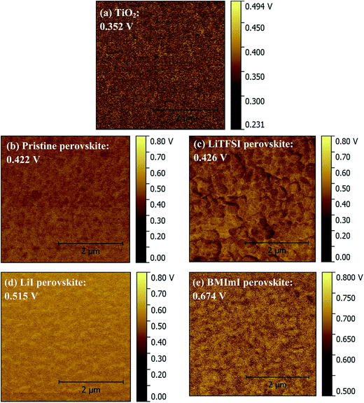
The back recombination barrier between titanium dioxide and the perovskite layer and within the grains of the perovskite layer could be studied through KPMF measurements. The device performance strongly depends on the alignment of energy levels of the electron transport material (TiO2) with those of the perovskite layer doped with different additives. The KPFM was conducted on the TiO2 and different MAPbI3 layers on planar samples. Fig. 4 and 5 show the surface potential images and surface potential distribution of TiO2, pristine perovskite and doped perovskite films. Fig. 4 shows that the surface potential of the perovskite film is not homogeneous when adding dopants into the PbI2 precursor solution which means that there are some regions having a higher potential than the others. This led to a downward band bending in the energy band diagram. Thus, the minority carrier “electrons” in the p-type absorber layer will be attracted from the regions with a higher surface potential towards those with the lower surface potential.16,40–42 This enhances minority carrier collection and provides an effective current pathway for minority carriers to reach the n-type layer. The surface potential of the perovskite film doped with BMImI has the highest surface potential. The surface potential distributions in Fig. 5 show that all the absorber perovskite films have a surface potential larger than that of the TiO2 electron transport layer. The TiO2 has an average surface potential value of 0.352 V. The surface potentials of perovskite films increased as a result of doping and follows the trend BMImI (0.674 V) > LiI (0.515 V) > LiTFSI (0.426 V) > no additive (0.422 V). The higher surface potential of the absorber increased the driving force of electron injection from perovskite to TiO2 leading to a higher Jsc. This agrees with the Jsc values BMImI > LiI > LiTFSI > no additive in the J–V curves in Fig. 7a and b.
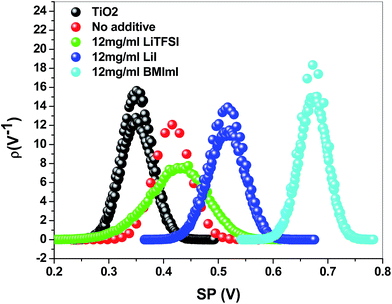 | ||
| Fig. 5 Surface potential distribution of perovskite (CH3NH3PbI3) films annealed at 100 °C for 15 min before and after adding BMImI, LiI, and LiTFSI additives in the PbI2 precursor. | ||
To understand the role of the additives in perovskite films via doping the PbI2 precursor solution, CS-AFM measurements for the pristine and doped perovskite films were carried out on their surfaces. Fig. 6 shows the CS-AFM results of different perovskite films. The pristine perovskite film has a lower surface current with the average value of 0.36 nA (Fig. 6a) than the doped perovskite films. As shown in Table 1, the average values of the surface current of perovskite films were 0.47 nA, 1.02 nA, and 1.16 nA when doping the PbI2 precursor solution with LiTFSI (Fig. 6b), LiI (Fig. 6c), and BMImI (Fig. 6d), respectively. These results suggest an improvement in the Jsc of the final perovskite solar cells after doping the PbI2 precursor solutions with LiTFSI, LiI, and BMImI. The average values of the surface current of perovskite films follow the order of BMImI > LiI > LiTFSI > no additive, which matches the order of Jsc in the J–V curves of Fig. 7a and b.
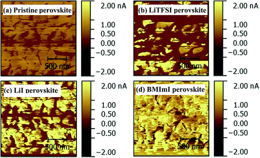 | ||
| Fig. 6 CS-AFM images of perovskite films (a) pristine and doped with (b) LiTFSI, (c) LiI and (d) BMImI on top of glass/FTO/TiO2. | ||
| Condition | Average value |
|---|---|
| No additive | 0.36 nA |
| 12 mg ml−1 LiTFSI | 0.47 nA |
| 12 mg ml−1 LiI | 1.02 nA |
| 12 mg ml−1 BMImI | 1.16 nA |
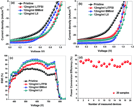
Fig. 7 shows the J–V curves and IPCE spectra of perovskite films prepared using the pristine PbI2 solution and that doped with an optimized concentration of additives LiTFSI, LiI and BMImI (12 mg ml−1). Various concentrations including 6 mg ml−1, 9 mg ml−1, 12 mg ml−1, 15 mg ml−1 of additives were studied to find the optimal concentration and the results are discussed in the ESI.† As shown in the ESI,† 12 mg ml−1 was found as the optimal concentration for additives LiTFSI, LiI and BMImI. The photovoltaic performance of perovskite solar cells was increased by doping PbI2 with LiTFSI, LiI and BMImI additives. Adding lithium and imidazolium iodide derivatives into the PbI2 layer leads to an increase in all the photovoltaic parameters including Jsc, Voc, fill factor (FF) and efficiency (η). Table 2 shows the photovoltaic parameters of fabricated perovskite solar cells before and after adding different additives into the PbI2 layer. The highest device efficiency was found to be 18% by adding BMImI additive into the precursor PbI2 solution while adding LiI and LiTFSI additives results in an enhancement in the efficiency (η) of the fabricated devices up to 17.01% and 15.6%, respectively, compared to 11.3% for the device fabricated from the pristine PbI2 solution. Jsc was improved from 23.01 mA cm−2 for the device fabricated using the pristine PbI2 solution when compared to 23.14, 23.36, and 24.70 mA cm−2 for the devices fabricated using LiTFSI, LiI, and BMImI doped PbI2 precursor solutions. The Jsc values of the fabricated solar cells are well matched with KPFM and CS-AFM results. The Jsc values of the fabricated solar cells made of doped perovskite films are higher than those of the solar cells fabricated with the pristine perovskite films in the order of BMImI > LiI > LiTFSI > no additive. KPFM results confirmed that the doped perovskite films have a higher surface potential than the undoped films, which increases the driving force of electron injection from perovskite to TiO2 thus increasing Jsc, while CS-AFM results showed that the doped perovskite films have a higher surface current than the undoped film. In addition, the increase in Jsc after doping with Li+ derivatives may be attributed to the adsorption of the small Li+ cation on the surface of TiO2. This positively charged Li+ cation has electron withdrawing properties that enhance electron injection from perovskite to TiO2 thus improving Jsc. The N heteroatoms of BMImI have electron donor properties. When they are adsorbed on the TiO2 surface, electrons are accumulated in the conduction band of TiO2 leading to an enhancement of Jsc and a positive shift in the Fermi level (EF) of TiO2. Thereby a suppression in electron recombination occurs. The Voc has been increased from 1.02 V for the device without doping to 1.07, 1.04, and 1.1 V after adding the additives LiTFSI, BMImI, and LiI, respectively.35Table 2 shows the great enhancement in the FF to 0.63, 0.66, and 0.7 after adding the additives LiTFSI, LiI and BMImI, respectively, into the PbI2 precursor solution compared to a FF of 0.48 for the pristine PbI2 solution. The photovoltaic parameters in Fig. 7a and b are in good agreement with results from XRD measurements, UV-vis spectra and AFM images.
| Additive | Scan | J sc (mA cm−2) | V oc (V) | FF | η (%) | EQE (%) |
|---|---|---|---|---|---|---|
| No additive | Forward | 22.87 | 0.94 | 0.47 | 10.1 | 70.97% |
| Reverse | 23.01 | 1.02 | 0.48 | 11.3 | ||
| LiTFSI | Forward | 22.94 | 1.02 | 0.58 | 13.57 | 83.49% |
| Reverse | 23.14 | 1.07 | 0.63 | 15.6 | ||
| BMImI | Forward | 24.03 | 0.98 | 0.51 | 12.1 | 91.69% |
| Reverse | 24.70 | 1.04 | 0.7 | 18 | ||
| LiI | Forward | 22.92 | 1.00 | 0.58 | 13.33 | 89.39% |
| Reverse | 23.36 | 1.10 | 0.66 | 17.01 |
The external quantum efficiency (EQE) in Fig. 7c is higher than 90% in the wavelength range of ca. 480–650 nm for the BMImI additive in the PbI2 solution. All the EQE spectra showed an enhancement after adding BMImI, LiI and LiTFSI additives into the PbI2 layer with the values of 91.69%, 89.39%, and 83.49%, respectively, compared to 70.97% for the control cell without any additives. The EQE increases are in good agreement with the J–V characteristics, UV-vis spectra, KPFM and CS-AFM results. The enhancement in EQE was attributed to the adsorption of positive cations, especially the small Li+ cations from LiTFSI, LiI, and BMImI onto the TiO2 surface which enhanced electron injection to the TiO2. Since the BMImI doping led to the highest efficiencies, we conducted reproducibility tests on the BMImI based devices, as shown in Fig. 7d. The highest efficiencies among the 20 cells are 18% with an average of about 16.3%. Hysteresis i.e., discrepancy that exists between forward and reverse voltage sweeps during current–voltage measurements is dominant in perovskites and one of the reasons attributed to this in most of the reports is ion migration due to excess ions as interstitial defects.43–45 In regard to this mechanism, it can be proposed that the doped perovskites have more ionic characteristics as the dopants are ionic and can be segregated into positively charged and negatively charged ionic species making the ion migration characteristics in the doped perovskites more pronounced. The accumulation of the excess ions can facilitate the polarization of the perovskite to make the hysteresis even more severe as seen in the doped perovskite solar cells.
Fig. 8a and b show charge transport time and charge carrier lifetime obtained from transient photocurrent (TPC) and transient photovoltage (TPV) measurements of perovskite solar cells prepared by doping the PbI2 precursor solution with LiI, LiTFSI and BMImI additives, respectively. The transient photocurrent and photovoltage were generated by a nanosecond pulse of a dye laser incident on solar cells under short circuit conditions using low impedance of 50 Ω and under open circuit conditions using high impedance of 1 MΩ. Charge transport time and charge carrier lifetime were obtained by fitting the decay function with a mono-exponential equation A![[thin space (1/6-em)]](https://www.rsc.org/images/entities/char_2009.gif) exp(−t/τ) where τ is the charge carrier life time. As shown in Table 3, charge carrier lifetimes of 7.78 μs, 9.10 μs and 9.91 μs were obtained for the cells containing BMImI, LiTFSI, and LiI in the PbI2 precursor, respectively. These are longer than the charge carrier life time of 5.94 μs for the cell without any additives. The longer charge carrier lifetime for additive-based cells can be attributed to the increase in Voc and larger perovskite grain size that can reduce trap states and recombination, thus improving the FF. The charge transport times of 0.84 μs, 2.59 μs and 5.24 μs (Table 3) were obtained for the cells containing BMImI, LiI and LiTFSI in the PbI2 precursor, respectively. These are shorter than that of 8.41 μs for the cell without any additives. This is a result of the adsorption of the positive cations of dopants on the surface of TiO2. Especially the small Li+ cations that penetrate deeply into the mesoporous nanocrystalline TiO2 films form an ambipolar Li+–e− with the electrons in the conduction band of TiO2. This improved electron transport in the nanocrystalline TiO2 network and enhanced the charge transport time, which is consistent with the Jsc and EQE results. These results match well with UV-vis spectra, KPFM, and CS-AFM results as discussed earlier.
exp(−t/τ) where τ is the charge carrier life time. As shown in Table 3, charge carrier lifetimes of 7.78 μs, 9.10 μs and 9.91 μs were obtained for the cells containing BMImI, LiTFSI, and LiI in the PbI2 precursor, respectively. These are longer than the charge carrier life time of 5.94 μs for the cell without any additives. The longer charge carrier lifetime for additive-based cells can be attributed to the increase in Voc and larger perovskite grain size that can reduce trap states and recombination, thus improving the FF. The charge transport times of 0.84 μs, 2.59 μs and 5.24 μs (Table 3) were obtained for the cells containing BMImI, LiI and LiTFSI in the PbI2 precursor, respectively. These are shorter than that of 8.41 μs for the cell without any additives. This is a result of the adsorption of the positive cations of dopants on the surface of TiO2. Especially the small Li+ cations that penetrate deeply into the mesoporous nanocrystalline TiO2 films form an ambipolar Li+–e− with the electrons in the conduction band of TiO2. This improved electron transport in the nanocrystalline TiO2 network and enhanced the charge transport time, which is consistent with the Jsc and EQE results. These results match well with UV-vis spectra, KPFM, and CS-AFM results as discussed earlier.
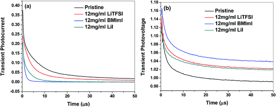 | ||
| Fig. 8 (a) Transient photocurrent and (b) transient photovoltage decay of perovskite solar cells before and after adding LiI, BMImI and LiTFSI additives into the PbI2 precursor. | ||
| Additive | Charge transport time (μs) | Charge carrier lifetime (μs) |
|---|---|---|
| No additive | 8.41 | 5.94 |
| LiTFSI | 5.24 | 9.10 |
| BMImI | 0.84 | 7.78 |
| LiI | 2.59 | 9.91 |
Fig. 9 shows the efficiency of the LiTFSI, LiI and BMImI doped and pristine perovskite solar cells over time with exposure to ambient conditions (relative humidity 40%). The cells were not encapsulated and characterized at periodic intervals. It was observed that the doped perovskite solar cells showed a much higher stability than the pristine cells. The BMImI, LiI and LiTFSI doped perovskite solar cells exhibited an efficiency decrease of 57%, 60%, and 91% respectively after exposure to air for 70 days versus a 93% decrease for pristine perovskite solar cell after only 24 days. This stability enhancement in LiI and LiTFSI incorporated perovskite solar cells may be attributed to the hygroscopic properties of the additives. These additives may serve as desiccant materials that will help prevent the degradation of the perovskite active material by moisture. Improved stability in BMImM incorporated perovskite solar cell can be attributed to the presence of the active [N] heteroatom of the heterocyclic imidazolium group with electron donating properties. Any organic compound containing C–H bonds can be degraded when exposed to light and heat giving rise to free radicals. The [N] heteroatom present in BMImI can enable it to act as a heat and light stabilizer by the binding of the [N] atom to the carbon radical via donating an electron, thus blocking its propagation into more free radicals and improving its stability.36
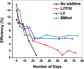 | ||
| Fig. 9 Efficiency of the LiTFSI, LiI and BMImI incorporated and pristine perovskite solar cells (not encapsulated) with respect to exposure time to ambient conditions (relative humidity 40%). | ||
Conclusions
In summary, we have demonstrated that the incorporation of additives BMImI, LiI and LiTFSI into the PbI2 precursor solution led to an enhancement in the stability of CH3NH3PbI3 perovskite solar cells along with higher efficiency. The new additive BMImI, LiI and LiTFSI incorporated CH3NH3PbI3 perovskite solar cells exhibited a 57%, 60%, and 91% decrease respectively after exposure to air for 70 days versus a 93% decrease for the pristine cell after only 24 days. The lithium salt additives LiI and LiTFSI led to higher stability attributed to their hygroscopic nature that enables them to serve as desiccants, thus preventing the degradation of the perovskite by moisture. Further, higher stability in the BMImI case can be attributed to the presence of the active [N] heteroatom of the heterocyclic imidazolium group that enables prevention of the formation of free radicals upon exposure to light and heat. In addition, incorporation of additives helped to achieve high efficiency perovskite solar cells with an efficiency of 18.0%, 17.01% and 15.6% for BMImI, LiI and LiTFSI respectively versus 11.3% for the pristine perovskite. Adding these additives resulted in the formation of perovskites with larger grain size and higher crystallinity with reduced PbI2 residue. This work is expected to open doors to further investigations of other additives as stabilizers towards achieving stable perovskites as stability is the major hurdle for commercialization of this technology.Conflicts of interest
There are no conflicts to declare.Acknowledgements
This work was also supported by the NASA Established Program to Stimulate Competitive Research (EPSCoR), U.S. – Egypt Science and Technology (S&T) Joint Fund, Pakistan-U.S. Science and Technology Cooperation Program, and NSF MRI (grant no. 1428992).References
- P. Cui, P. Fu, D. Wei, M. Li, D. Song, X. Yue, Y. Li, Z. Zhang, Y. Li and J. M. Mbengue, RSC Adv., 2015, 5, 75622–75629 RSC.
- W.-J. Yin, T. Shi and Y. Yan, Appl. Phys. Lett., 2014, 104, 063903 CrossRef.
- J. S. Manser, B. Reid and P. V. Kamat, J. Phys. Chem. C, 2015, 119, 17065–17073 CAS.
- F. Hao, C. C. Stoumpos, Z. Liu, R. P. H. Chang and M. G. Kanatzidis, J. Am. Chem. Soc., 2014, 136, 16411–16419 CrossRef CAS PubMed.
- H. J. Snaith, Energy Environ. Sci., 2012, 5, 6513–6520 Search PubMed.
- A. Kojima, K. Teshima, Y. Shirai and T. Miyasaka, J. Am. Chem. Soc., 2009, 131, 6050–6051 CrossRef CAS PubMed.
- M. A. Green, K. Emery, Y. Hishikawa, W. Warta and E. D. Dunlop, Prog. Photovoltaics, 2015, 23, 1–9 Search PubMed.
- V. W. Bergmann, S. A. Weber, F. J. Ramos, M. K. Nazeeruddin, M. Grätzel, D. Li, A. L. Domanski, I. Lieberwirth, S. Ahmad and R. Berger, Nat. Commun., 2014, 5, 3689 Search PubMed.
- C.-S. Jiang, M. Yang, Y. Zhou, B. To, S. U. Nanayakkara, J. M. Luther, W. Zhou, J. J. Berry, J. van de Lagemaat and N. P. Padture, Nat. Commun., 2015, 6, 8397 CrossRef CAS PubMed.
- C. Bu, Q. Tai, Y. Liu, S. Guo and X. Zhao, J. Power Sources, 2013, 221, 78–83 CrossRef CAS.
- N. J. Jeon, J. H. Noh, W. S. Yang, Y. C. Kim, S. Ryu, J. Seo and S. I. Seok, Nature, 2015, 517, 476–480 CrossRef CAS PubMed.
- N. Adhikari, A. Dubey, D. Khatiwada, A. F. Mitul, Q. Wang, S. Venkatesan, A. Iefanova, J. Zai, X. Qian and M. Kumar, ACS Appl. Mater. Interfaces, 2015, 7(48), 26445–26454 CAS.
- A. Dubey, N. Adhikari, S. Venkatesan, S. Gu, D. Khatiwada, Q. Wang, L. Mohammad, M. Kumar and Q. Qiao, Sol. Energy Mater. Sol. Cells, 2016, 7, 139–142 Search PubMed.
- D. Khatiwada, S. Venkatesan, N. Adhikari, A. Dubey, A. F. Mitul, L. Mohammad, A. Iefanova, S. B. Darling and Q. Qiao, J. Phys. Chem. C, 2015, 119(46), 25747–25753 CAS.
- Y. Rong, Z. Tang, Y. Zhao, X. Zhong, S. Venkatesan, H. Graham, M. Patton, Y. Jing, A. M. Guloy and Y. Yao, Nanoscale, 2015, 7, 10595–10599 RSC.
- N. Adhikari, A. Dubey, E. A. Gaml, B. Vaagensmith, K. M. Reza, S. A. A. Mabrouk, S. Gu, J. Zai, X. Qian and Q. Qiao, Nanoscale, 2016, 8, 2693–2703 RSC.
- J. A. Christians, P. A. Miranda Herrera and P. V. Kamat, J. Am. Chem. Soc., 2015, 137, 1530–1538 CrossRef CAS PubMed.
- H. Zhou, Q. Chen, G. Li, S. Luo, T. B. Song, H. S. Duan, Z. Hong, J. You and Y. Yang, Science, 2014, 345, 542 CrossRef CAS PubMed.
- B. Hailegnaw, S. Kirmayer, E. Edri, G. Hodes and D. Cahen, J. Phys. Chem. Lett., 2015, 6, 1543–1547 CrossRef CAS PubMed.
- A. Thapa, J. Zai, H. Elbohy, P. Poudel, N. Adhikari, X. Qian and Q. Qiao, Nano Res., 2014, 7, 1154–1163 CrossRef CAS.
- J. Sun, L. Zhang, A. Dubey, S. Venkatesan, T.-Y. Lin, L. P. Sanow, Y.-C. Hung, A. Sykes, H. He, Q. Qiao and C. Zhang, Proc. SPIE, 2013, 8830, 88302L CrossRef.
- M. Kumar, A. Dubey, K. M. Reza, N. Adhikari, Q. Qiao and V. Bommisetty, Phys. Chem. Chem. Phys., 2015, 17, 27690–27697 RSC.
- D. Khatiwada, S. Venkatesan, J. Chen, Q. Chen, N. Adhikari, A. Dubey, A. F. Mitul, L. Mohammad, J. Sun and C. Zhang, IEEE Trans. Electron Devices, 2015, 62, 1284–1290 CrossRef CAS.
- A. F. Mitul, L. Mohammad, B. Vaagensmith, A. Dubey, D. Khatiwada and Q. Qiao, IEEE J. Photovolt., 2015, 5(6), 1674–1679 CrossRef.
- N. Adhikari, D. Khatiwada, A. Dubey and Q. Qiao, J. Photonics Energy, 2015, 5, 057207 CrossRef.
- N. S. An, Y. N. Shi, J. Q. Feng, D. P. Li, J. Gao, Y. L. Chen and X. Y. Li, Org. Electron., 2013, 14, 1197–1203 CrossRef CAS.
- S. Colella, E. Mosconi, G. Pellegrino, A. Alberti, V. L. Guerra, S. Masi, A. Listorti, A. Rizzo, G. G. Condorelli and F. De Angelis, J. Phys. Chem. Lett., 2014, 5, 3532–3538 CrossRef CAS PubMed.
- H. Zhang, J. Mao, H. He, D. Zhang, H. L. Zhu, F. Xie, K. S. Wong, M. Grätzel and W. C. Choy, Adv. Energy Mater., 2015, 5(23), 1501354 CrossRef.
- P. P. Boix, S. Agarwala, T. M. Koh, N. Mathews and S. G. Mhaisalkar, J. Phys. Chem. Lett., 2015, 6, 898–907 CrossRef CAS PubMed.
- N. K. Noel, S. D. Stranks, A. Abate, C. Wehrenfennig, S. Guarnera, A.-A. Haghighirad, A. Sadhanala, G. E. Eperon, S. K. Pathak, M. B. Johnston, A. Petrozza, L. M. Herz and H. J. Snaith, Energy Environ. Sci., 2014, 7, 3061–3068 CAS.
- T. Zhang, M. Yang, Y. Zhao and K. Zhu, Nano Lett., 2015, 15, 3959–3963 CrossRef CAS PubMed.
- G. Li, T. Zhang and Y. Zhao, J. Mater. Chem. A, 2015, 3, 19674–19678 CAS.
- C.-G. Wu, C.-H. Chiang, Z.-L. Tseng, M. K. Nazeeruddin, A. Hagfeldt and M. Grätzel, Energy Environ. Sci., 2015, 8, 2725–2733 CAS.
- X. Gong, M. Li, X. B. Shi, H. Ma, Z. K. Wang and L. S. Liao, Adv. Funct. Mater., 2015, 25, 6671–6678 CrossRef CAS.
- S. Mabrouk, A. Dubey, W. Zhang, N. Adhikari, B. Bahrami, M. N. Hasan, S. Yang and Q. Qiao, J. Phys. Chem. C, 2016, 120, 24577–24582 CAS.
- N. Ahn, D.-Y. Son, I.-H. Jang, S. M. Kang, M. Choi and N.-G. Park, J. Am. Chem. Soc., 2015, 137, 8696–8699 CrossRef CAS PubMed.
- S. Venkatesan, N. Adhikari, J. Chen, E. C. Ngo, A. Dubey, D. W. Galipeau and Q. Qiao, Nanoscale, 2014, 6, 1011–1019 RSC.
- J. S. Yun, A. Ho-Baillie, S. Huang, S. H. Woo, Y. Heo, J. Seidel, F. Huang, Y.-B. Cheng and M. A. Green, J. Phys. Chem. Lett., 2015, 6, 875–880 CrossRef CAS PubMed.
- A. Dymshits, A. Henning, G. Segev, Y. Rosenwaks and L. Etgar, Sci. Rep., 2015, 5, 8704 CrossRef CAS PubMed.
- J. Y. Seto, J. Appl. Phys., 1975, 46, 5247–5254 CrossRef CAS.
- J. B. Li, V. Chawla and B. M. Clemens, Adv. Mater., 2012, 24, 720–723 CrossRef CAS PubMed.
- M. Kumar, A. Dubey, N. Adhikari, S. Venkatesan and Q. Qiao, Energy Environ. Sci., 2015, 8, 3134–3159 CAS.
- H. J. Snaith, A. Abate, J. M. Ball, G. E. Eperon, T. Leijtens, N. K. Noel, S. D. Stranks, J. T.-W. Wang, K. Wojciechowski and W. Zhang, J. Phys. Chem. Lett., 2014, 5, 1511–1515 CrossRef CAS PubMed.
- C. Li, S. Tscheuschner, F. Paulus, P. E. Hopkinson, J. Kießling, A. Köhler, Y. Vaynzof and S. Huettner, Adv. Mater., 2016, 28, 2446–2454 CrossRef CAS PubMed.
- Y. Zhang, M. Liu, G. E. Eperon, T. C. Leijtens, D. McMeekin, M. Saliba, W. Zhang, M. de Bastiani, A. Petrozza and L. M. Herz, Mater. Horiz., 2015, 2, 315–322 RSC.
Footnote |
| † Electronic supplementary information (ESI) available. See DOI: 10.1039/c7se00435d |
| This journal is © The Royal Society of Chemistry 2017 |

