
Optically transparent fluorine-containing polycarbonates with high refractive indices for thermo-optic switches†
Zhenzhen
Cai
a,
Yuping
Zhang
a,
Yilong
Song
a,
Qiuli
Cheng
a,
Yang
Zheng
b,
Zhanchen
Cui
 *ac,
Zuosen
Shi
*a,
Changming
Chen
b and
Daming
Zhang
b
*ac,
Zuosen
Shi
*a,
Changming
Chen
b and
Daming
Zhang
b
aState Key Laboratory of Supramolecular Structure and Materials, Jilin University, Changchun 130012, People's Republic of China. E-mail: cuizc@jlu.edu.cn
bState Key Lab on Integrated Opto-electronics, Jilin University Region, Changchun 130012, People's Republic of China
cDepartment of Chemistry and Pharmacy, Zhuhai College of Jilin University, Zhuhai 519041, People's Republic of China
First published on 13th June 2017
Abstract
In this paper, we report the design, synthesis, and optical properties of novel negative-type fluorinated polycarbonate photoresists (FPC-PRs) and their use in thermo-optic switches. The novel polymer films are readily fabricated by spin coating on a silicon wafer followed by irradiation with UV light and post-baking at 110 °C. These films exhibit low roughness, good thermal stability (Td, up to 292 °C), high transparency (up to 97.8% at 400 nm) and high refractive indices (RI, 1.583–1.512 at 1550 nm). Channel optical waveguide and MZI thermo-optic waveguide switch arrays were fabricated based on the direct UV-written technique using the FPC-PR 2. The propagation loss of the channel waveguide was only 0.17 dB cm−1 at 1550 nm. The rise and fall times of the device with an applied 500 Hz square-wave voltage were 837 μs and 381.8 μs, respectively. The applied electric power as the switching power was about 35 mW, and the extinction ratio was measured to be about 14.0 dB.
Introduction
In recent years, much attention has been paid to the development of functional materials for the progress of advanced optical devices.1 Polymeric materials possessing high refractive indices and high Abbe numbers combined with good thermal stability and high transparency have attracted significant interest because of their applications as micro-optic and optoelectronic materials including lenses, prisms, antireflective coatings and optical waveguide systems, based on their advantages of light weight and flexibility.2The theory of guided-wave optics is the phenomenon of total internal reflection (TIR). This phenomenon can confine light in the optical waveguide, with other materials with lower refractive indices as the surround materials. On the basis of this theory, the polymer used as the core material must have a higher refractive index than the cladding polymer. The appropriate index difference between the core material and the cladding polymer for the waveguide is mainly attributable to two factors. One is the dimension of the waveguide and the other is the wavelength of the light source. For the polymers, an important feature is the controllability of the refractive-index contrast, resulting in high-density compact wave-guiding structures with small radii of curvature becoming possible. Compact structures are critical for the realization of a large-scale photonic integration.3
Polymer-based optical switches, for example, digital optical switches, Mach–Zehnder interferometer (MZI) switches, directional coupler switches and total-internal reflection switches,4 are some of the key devices for optical communication systems and play important roles in the applications in optical connects (OXCs), optical add-drop multiplexers (OADMs), optical network monitoring and on-chip optical interconnection.5 The optical loss is an important issue in this domain. All optical waveguide devices need to have a low absorption loss at the optic communication wavelengths (e.g. 1310 and 1550 nm). For this reason, replacing C–H bonds with C–F bonds in polymers is desirable for reducing the optical loss at the telecommunication wavelengths.6 Moreover, fluorine-containing polymers are more attractive for waveguide applications, taking into account the properties, such as low moisture absorption, and good thermal and chemical stability.7 However, the poor adhesion to substrates, low refractive index and low transparency, high surface energy and crystalline properties of fluorinated polymers have limited their applications in waveguide devices.8 With the intention of enhancing the adhesion of the polymer layer to the substrates, polar functional groups such as carbonate or carbamate groups can be introduced.9 The remarkable success of bisphenol A-polycarbonate derives from the versatility of its applications, which are a function of its properties, including transparency, heat resistance, and excellent impact toughness.10
Herein, epoxy groups as crosslinking sites and biphenyl, to increase and adjust the refractive indices, were introduced into the fluorinated polycarbonate backbone to prepare a series of fluorinated epoxy-terminated polycarbonates (FBPA-PC-EPs), and a series of negative-type fluorinated photoresists (FPC-PRs) were prepared by mixing them with the solvent and a photo-initiator. Through the direct-UV-written lithography process, a FPC-PR could be fabricated into a channel waveguide and transformed into a cross-linked structure. This FPC-PR shows good performance in film fabrication, and the channel waveguide fabricated from it has low optical propagation loss, high transparency, sufficient thermal stability, favorable processability and an adjustable refractive index. Based on these materials, MZI thermo-optic waveguide switch arrays were successfully fabricated, and the switches exhibit lower insertion loss and shorter response time, which proves that FBPA-PC-EPs could be used as suitable candidates for optical communication thermo-optic switch devices.
Experimental
Materials
4,4′-(Hexafluoroisopropylidene)diphenol (6FBPA), 3-(trifluoromethyl)aniline and triphosgene (BTC) were purchased from Aladdin and used as received. (3-Trifluoromethyl)phenyl hydroquinone (3F-PQ) was synthesized according to a literature procedure.11 Triphenylsulfonium hexafluorophosphate was purchased from Sigma-Aldrich and used as received. Epoxy chloropropane, pyridine and dichloromethane were purchased from Beijing Chemical Reagent Co. (China) and were of analytical grade and used after purification. The other chemicals such as sodium nitrite, sodium hydrogen carbonate and hydrochloric acid were purchased from Beijing Chemical Co. (China) and used without further purification.Measurement
The structures of all synthetic intermediates and epoxy-terminated polymers were confirmed by 1H NMR, 13C NMR and 19F NMR spectroscopy using a Bruker AVANCE NMR spectrometer operating at 500 MHz and 470 MHz, respectively. IR spectra (KBr) were recorded on an AVATAR 360 transform infrared (FT-IR) spectrophotometer. The number-average molecular weights (Mn) and molecular weight distribution (MWD) dispersities (Đ = Mw/Mn) of the polymers were determined by gel permeation chromatography (GPC) with polystyrene standards using THF as the eluent with a flow rate of 1.0 mL min−1 at 25 °C. The glass transition temperature of polymers was determined by using differential scanning calorimetry (DSC) measurements recorded on a NETZSCH 4 instrument at a scan rate of 8 °C min−1 in the temperature range of −50 to 300 °C under nitrogen. Thermal stability of the polymers was analyzed using a Perkin-Elmer TGA 7 analyzer from 20 °C to 900 °C at a heating rate of 10 °C min−1 under a nitrogen atmosphere. Atomic force microscopy (AFM) was obtained on a commercial instrument, Digital Instruments, Nanoscope IIIa Multimode, to observe the roughness of the film surface under ambient conditions at room temperature. An Uvisel 2 spectroscopic ellipsometer was used to determine the refractive index of the film. UV-vis-NIR spectra were obtained using a SHIMADZU UV-3600 spectrophotometer. Scanning electron microscopy (SEM) was performed using a JEOL FESEM 6700F electron microscope.Synthesis of fluorinated hydroxyl-terminated polycarbonates (FBPA-PC-OHs)
The typical procedure was listed as follows: 6F-BPA and 3F-PQ were dissolved with pyridine in a round-bottom flask equipped with a magnetic stir bar and then chilled in an ice bath. Triphosgene was dissolved in dry methylene chloride and then added dropwise; the mixture was stirred at 0 °C for 30 min and at room temperature for 6 h. After that, the mixture was washed with water several times and dried over anhydrous MgSO4. At last, the orange phase was precipitated in methanol, and the precipitate was filtered and collected subsequently. The product was dried at room temperature under vacuum for 24 hours and was denoted as FBPA-PC-OH.FBPA-PC-OH-1: 6F-BPA (5.38 g, 16 mmol), 3F-PQ (0.51 g, 2 mmol), triphosgene (1.49 g, 5 mmol) and pyridine (2.4 mL). FBPA-PC-OH-1 was obtained as a white powder (4.9 g, 78%). Mn = 1.05 × 10⁴; Mw/Mn = 1.31. IR (KBr, cm−1): γ (C–F) = 1165–1337, γ (aromatic) = 1615 and 1513, γ (CO–O–Ar) = 1785. 1H NMR (500 MHz, CDCl3): δ (ppm) 7.83 (s, 1H, ArH), 7.73–7.74 (t, 2H, ArH), 7.65 (s, 1H, ArH), 7.50–7.51 (m, 31H, ArH), 7.35–7.37 (m, 31H, ArH), 7.02–7.03 (t, 2H, ArH), 6.81 (s, 1H, ArH). 13C NMR (125 MHz, CDCl3): δ (ppm) 151.20, 151.13, 151.02, 149.04, 145.54, 134.55, 132.25, 131.67, 131.26, 129.36, 125.62, 123.94, 123.59, 123.23, 121.76, 120.75, 120.51, 118.91, 115.14, 64.20. 19F NMR (470 MHz, CDCl3, CFCl3): δ (ppm) −62.56 (3F, Ar-CF3), −63.87 (6F, –CF3).
FBPA-PC-OH-2: 6F-BPA (6.05 g, 18 mmol), 3F-PQ (0.77 g, 3 mmol), triphosgene (1.73 g, 5.83 mmol) and pyridine (2.8 mL). FBPA-PC-OH-2 was obtained as a white powder (5.6 g, 76%). Mn = 1.09 × 10⁴; Mw/Mn = 1.33. IR (KBr, cm−1): γ (C–F) = 1162–1336, γ (aromatic) = 1614 and 1509, γ (CO–O–Ar) = 1788. 1H NMR (500 MHz, CDCl3): δ (ppm) 7.83 (s, 1H, ArH), 7.73–7.74 (t, 2H, ArH), 7.63 (s, 1H, ArH), 7.49–7.51 (m, 22H, ArH), 7.35–7.37 (m, 22H, ArH), 7.01–7.03 (t, 2H, ArH), 6.82 (s, 1H, ArH). 13C NMR (125 MHz, CDCl3): δ (ppm) 151.21, 151.14, 151.03, 149.06, 145.54, 134.56, 132.27, 131.67, 131.25, 129.34, 125.64, 123.94, 123.56, 123.23, 121.77, 120.74, 120.51, 118.92, 115.16, 64.21. 19F NMR (470 MHz, CDCl3, CFCl3): δ (ppm) −62.57 (3F, Ar-CF3), −63.87 (6F, –CF3).
FBPA-PC-OH-3: 6F-BPA (5.38 g, 16 mmol), 3F-PQ (1.02 g, 4 mmol), triphosgene (1.65 g, 5.56 mmol) and pyridine (2.7 mL). FBPA-PC-OH-3 was obtained as a white powder (5.1 g, 74%). Mn = 1.12 × 10⁴; Mw/Mn = 1.38. IR (KBr, cm−1): γ (C–F) = 1173–1330, γ (aromatic) = 1614 and 1514, γ (CO–O–Ar) = 1781. 1H NMR (500 MHz, CDCl3): δ (ppm) 7.83 (s, 1H, ArH), 7.73–7.74 (t, 2H, ArH), 7.63 (s, 1H, ArH), 7.50–7.51 (m, 16H, ArH), 7.35–7.37 (m, 16H, ArH), 7.02–7.03 (t, 2H, ArH), 6.82 (s, 1H, ArH). 13C NMR (125 MHz, CDCl3): δ (ppm) 151.20, 151.13, 151.02, 149.05, 145.45, 134.58, 132.29, 131.67, 131.26, 129.35, 125.64, 123.94, 123.58, 123.23, 121.77, 120.75, 120.52, 118.97, 115.16, 64.20. 19F NMR (470 MHz, CDCl3, CFCl3): δ (ppm) −62.56 (3F, Ar-CF3), −63.87 (6F, –CF3).
Synthesis of fluorinated epoxy-terminated polycarbonates (FBPA-PC-EPs)
The solid FBPA-PC-OH from the previous step was dissolved with epoxy chloropropane in a round-bottomed flask equipped with a mechanical stirrer and a water condenser. The mixture was heated to 55 °C while stirring, and was maintained for 5 h. During this process, the sodium hydroxide was added every 30 min. Then, the mixture was heated to 60 °C, and stirred for another 6 h. At last, the excess of epoxy chloropropane was removed under vacuum by rotary evaporation at 60 °C. Dichloromethane was then added to the product solution. Sodium chloride was filtered off and the filtrate was evaporated under a reduced pressure to remove dichloromethane. The product was obtained as an oil. The preparation and structure of FBPA-PA-EPs are illustrated in Scheme 1. | ||
| Scheme 1 The fabrication process of epoxy-terminated polycarbonates (FBPA-PC-EPs). | ||
FBPA-PC-EP-1: FBPA-PC-OH-1 (5.38 g, 0.51 mmol), epoxy chloropropane (20 g, 0.204 mol) and sodium hydroxide (0.102 g, 2.55 mmol). FBPA-PC-EP-1 was obtained as a light yellow viscous liquid (5.17 g, 96.1%). Mn = 1.05 × 10⁴; Mw/Mn = 1.30 (Fig. S1, ESI†). IR (KBr, cm−1): γ (C–F) = 1172–1338, γ (CO–O–Ar) = 1760, γ (aromatic) = 1617 and 1521, γ (epoxy group) = 833. 1H NMR (500 MHz, CDCl3): δ (ppm) 7.83 (s, 3H, ArH), 7.73–7.74 (t, 6H, ArH), 7.65 (s, 3H, ArH), 7.50–7.51 (m, 93H, ArH), 7.35–7.37 (m, 93H, ArH), 7.02–7.03 (t, 6H, ArH), 6.81 (s, 3H, ArH), 4.27–4.30 (m, 2H, –CH2), 3.96–4.00 (m, 2H, –CH2), 3.38–3.39 (m, 2H, –CH), 2.93–2.94 (m, 2H, –CH2), 2.78–2.79 (m, 2H, –CH2). 13C NMR (125 MHz, CDCl3): δ (ppm) 158.66, 158.63, 158.44, 158.14, 153.63, 153.00, 131.57, 131.47, 128.65, 128.52, 126.36, 126.17, 125.92, 125.83, 124.30, 123.99, 120.01, 117.62, 114.13, 68.79, 63.43, 50.02, 44.61. 19F NMR (470 MHz, CDCl3, CFCl3): δ (ppm) −62.46 (3F, Ar-CF3), −64.16 (6F, –CF3).
FBPA-PC-EP-2: FBPA-PC-OH-2 (5.6 g, 0.514 mmol), epoxy chloropropane (20 g, 0.206 mol) and sodium hydroxide (0.103 g, 2.57 mmol). FBPA-PC-EP-2 was obtained as a light yellow viscous liquid (5.38 g, 96%). Mn = 1.09 × 10⁴; Mw/Mn = 1.34 (Fig. S2, ESI†). IR (KBr, cm−1): γ (C–F) = 1174–1341, γ (CO–O–Ar) = 1757, γ (aromatic) = 1614 and 1510, γ (epoxy group) = 831. 1H NMR (500 MHz, CDCl3): δ (ppm) 7.83 (s, 2H, ArH), 7.73–7.74 (t, 4H, ArH), 7.63 (s, 2H, ArH), 7.49–7.51 (m, 44H, ArH), 7.35–7.37 (m, 44H, ArH), 7.01–7.03 (t, 4H, ArH), 6.82 (s, 2H, ArH), 4.27–4.30 (m, 1H, –CH2), 3.97–3.99 (m, 1H, –CH2), 3.38–3.39 (m, 1H, –CH), 2.92–2.94 (m, 1H, –CH2), 2.77–2.79 (m, 1H, –CH2). 13C NMR (125 MHz, CDCl3): δ (ppm) 158.67, 158.63, 158.42, 158.13, 153.64, 153.01, 131.58, 131.49, 128.66, 128.52, 126.34, 126.15, 125.92, 125.84, 124.31, 123.97, 120.00, 117.61, 114.14, 68.80, 63.41, 50.00, 44.60. 19F NMR (470 MHz, CDCl3, CFCl3): δ (ppm) −62.48 (3F, Ar-CF3), −64.15 (6F, –CF3).
FBPA-PC-EP-3: FBPA-PC-OH-3 (5.1 g, 0.454 mmol), epoxy chloropropane (17.8 g, 0.182 mol) and sodium hydroxide (0.091 g, 2.27 mmol). FBPA-PC-EP-3 was obtained as a light yellow viscous liquid (4.94 g, 96.8%). Mn = 1.12 × 10⁴; Mw/Mn = 1.36 (Fig. S3, ESI†). IR (KBr, cm−1): γ (C–F) = 1171–1337, γ (CO–O–Ar) = 1761, γ (aromatic) = 1610 and 1519, γ (epoxy group) = 833. 1H NMR (500 MHz, CDCl3): δ (ppm) 7.83 (s, 7H, ArH), 7.73–7.74 (t, 14H, ArH), 7.63 (s, 7H, ArH), 7.50–7.51 (m, 112H, ArH), 7.35–7.37 (m, 112H, ArH), 7.02–7.03 (t, 14H, ArH), 6.82 (s, 7H, ArH), 3.95–3.99 (2H, m, –CH2), 3.57–3.60 (2H, m, –CH2), 3.36–3.38 (2H, m, –CH), 2.92–2.94 (2H, m, –CH2), 2.77–2.78 (2H, m, –CH2). 13C NMR (125 MHz, CDCl3): δ (ppm) 158.66, 158.63, 158.42, 158.13, 153.64, 153.00, 131.57, 131.45, 128.66, 128.54, 126.36, 126.16, 125.92, 125.82, 124.30, 124.01, 120.01, 117.63, 114.11, 68.79, 63.44, 50.01, 44.61. 19F NMR (470 MHz, CDCl3, CFCl3): δ (ppm) −62.43 (3F, Ar-CF3), −64.15 (6F, –CF3).
The polymer film preparation
To determine the optical properties and fabricate the optical waveguide, negative-type fluorinated photoresists were formulated by mixing the synthesized FBPA-PC-EPs and an initiator into cyclopentanone to form the 30–60 wt% solutions (FPC-PR 1–3). FPC-PRs were filtered (PTFE, 0.2 μm) directly before spin-coated on top of the Si/SiO2 wafer substrates. The spin-coated films were annealed at 110 °C for 60 min to remove the solvent, and then were irradiated with UV light for 6 min prior to the post-bake at 110 °C for 30 min.Waveguide device fabrication
To research the application of FPC-PRs in an optical waveguide, the channel waveguide and MZI thermo-optic waveguide switch arrays were fabricated as reported in ref. 12.As shown in Fig. 1, the procedure to fabricate the device consisted of an initial bake at 110 °C for 60 min prior to UV illumination through a contact chromium mask for 6 min. Then, patterns were post-baked at 110 °C for 30 min and consequently developed with propylene glycol monomethyl ether acetate (PGMEA) at room temperature, followed by blowing dry to form the desirable waveguides. At the end of the process, PMMA was spin-coated onto the core layer and baked at 125 °C for 1 h to form the upper cladding film.
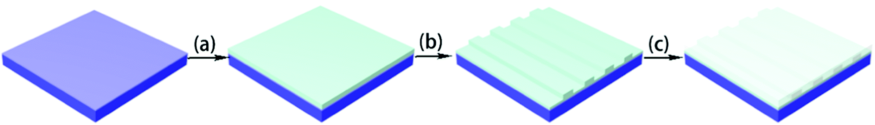 | ||
| Fig. 1 Fabrication process of a straight waveguide, the process involves (a) coating the substrate with a photoresist and annealing at 110 °C for 60 min, (b) exposure to UV light through a contact chromium mask for 6 min, post-baking at 110 °C for 30 min and developing in the negative mode with propylene glycol monomethyl ether acetate for 5 s, and (c) coating with PMMA as the upper cladding. | ||
The schematic configurations of both the waveguide and electrode heater masks of the thermo-optic waveguide switch arrays are presented in Fig. 2. Firstly, as described in the process, to fabricate the channel waveguide, FPC-PR 2 was spin-coated on the SiO2/Si wafer to form a 4 μm-thick thin film as the core layer. Secondly, a 2 μm-thick PMMA film was formed as the upper cladding, followed by a curing-bake at 125 °C for 1 h. Then, the gold stripes were patterned by photolithography and wet etching. It could be noted that every group of electrodes was designed to be in different widths so as to make the switch arrays be capable of achieving periodic intensity modulation when combined with the fiber arrays.
 | ||
| Fig. 2 Schematics of MZI thermo-optic waveguide switch arrays. | ||
Results and discussion
Structure characterization
We prepared FBPA-PC-EPs with a trifluoromethyl group and an epoxy unit as a cross-linking site. Firstly, for the purpose of obtaining the FBPA-PC-EPs, the FBPA-PC-OHs were synthesized. To achieve the FBPA-PC-OHs, the molar feed ratio of (6FBPA + 3F-PQ)![[thin space (1/6-em)]](https://www.rsc.org/images/entities/char_2009.gif) :BTC was controlled as 18:5. The FBPA-PC-OHs were isolated as white solids, and their structures were confirmed by 1H NMR, 13C NMR, 19F NMR and FT-IR. In the 1H NMR spectra (Fig. S4, ESI†), the characteristic peaks of the 3F-PQ in FBPA-PC-OH 1–3 were observed at 7.83, 7.73–7.74, 7.63, 7.02–7.03 and 6.82 ppm. The compositions of the copolymers (FBPA-PC-OH 1–3) calculated using 1H NMR spectra were 6FBPA/3F-PQ = 7.75:1, 5.5:1, and 4:1 according to feed ratios. In the 19F spectra (Fig. S5, ESI†), the signals at −62.56 and −63.87 ppm were attributed to the trifluoromethyl of 3F-PQ and 6FBPA, respectively. In the second step, we synthesized the FBPA-PC-EPs with FBPA-PC-OHs and epoxy chloropropane. In the 1H NMR spectra, the characteristic peaks of the epoxy group were observed at 2.77–2.79, 2.92–2.94, 3.38–3.39, 3.97–3.99 and 4.27–4.30 ppm. In the 13C spectra (Fig. S6, ESI†), the signals at 68.79, 50.02 and 44.61 ppm were attributed to the epoxy group. In the FT-IR spectrum (Fig. S7, ESI†), the absorption at 830 cm−1 was attributed to the epoxy group of the FBPA-PC-EPs, too. These results indicate that we have successfully introduced the epoxy groups into the FBPA-PC-EPs and the content of 3F-PQ in the FBPA-PC-EPs could be well controlled by adjusting the feed.
:BTC was controlled as 18:5. The FBPA-PC-OHs were isolated as white solids, and their structures were confirmed by 1H NMR, 13C NMR, 19F NMR and FT-IR. In the 1H NMR spectra (Fig. S4, ESI†), the characteristic peaks of the 3F-PQ in FBPA-PC-OH 1–3 were observed at 7.83, 7.73–7.74, 7.63, 7.02–7.03 and 6.82 ppm. The compositions of the copolymers (FBPA-PC-OH 1–3) calculated using 1H NMR spectra were 6FBPA/3F-PQ = 7.75:1, 5.5:1, and 4:1 according to feed ratios. In the 19F spectra (Fig. S5, ESI†), the signals at −62.56 and −63.87 ppm were attributed to the trifluoromethyl of 3F-PQ and 6FBPA, respectively. In the second step, we synthesized the FBPA-PC-EPs with FBPA-PC-OHs and epoxy chloropropane. In the 1H NMR spectra, the characteristic peaks of the epoxy group were observed at 2.77–2.79, 2.92–2.94, 3.38–3.39, 3.97–3.99 and 4.27–4.30 ppm. In the 13C spectra (Fig. S6, ESI†), the signals at 68.79, 50.02 and 44.61 ppm were attributed to the epoxy group. In the FT-IR spectrum (Fig. S7, ESI†), the absorption at 830 cm−1 was attributed to the epoxy group of the FBPA-PC-EPs, too. These results indicate that we have successfully introduced the epoxy groups into the FBPA-PC-EPs and the content of 3F-PQ in the FBPA-PC-EPs could be well controlled by adjusting the feed.
Properties of photo-crosslinking films
 | ||
| Fig. 3 Near-infrared absorption (A) and transmittance (B) spectra of FPC-PRs. | ||
 | ||
| Fig. 4 (A) Wavelength dependence of the refractive indices of the thin films of the FPC-PRs; (B) relationship between the refractive indices of the FPC-PR films and the content of 3F-PQ. | ||
In order to clarify the potential of the polymers as optical materials, we chose to measure the value of optical dispersion, and the smaller the value the better.16 Apart from this, a modified Abbe number (νD′) has been proposed to evaluate the application potential of an optical material, using its RI values at the nonabsorbing wavelengths of 1064, 1319, and 1550 nm.17 The first two wavelengths are chosen in view of the practical interest of commercial laser wavelengths, while the last one is the wavelength for telecommunication. The results are shown in Table 1. The νD values of FPC-PR 1–3 range from 33.19 to 35.53, which were similar to those of conjugated polymers (majority between 10 and 20).18 The νD′ values were much higher (128.5–146.0) and hence the lower D′ (0.0078–0.0068).
| Polymer | n 1550 | ν D |
ν
D′c |
D |
D′e |
|---|---|---|---|---|---|
| a Abbreviation: n = refractive index (at 1550 nm). b ν D = Abbe number [defined as (nD − 1)/(nF − nC), where nD, nF, and nC are the refractive indices at wavelengths of the sodium D (589.2), hydrogen F (486.1), and hydrogen C (656.3 nm) lines, respectively]. c ν D′ = modified Abbe number [defined as (n1319 − 1)/(n1064 − n1550), where n1319, n1064, and n1550 are the refractive indices at the nonabsorbing wavelengths at 1064, 1319, and 1550 nm]. d D = optical dispersion = 1/νD. e D′ = optical dispersion = 1/νD′. | |||||
| FPC-PR 1 | 1.512 | 33.19 | 128.50 | 0.0301 | 0.0078 |
| FPC-PR 2 | 1.536 | 34.69 | 134.25 | 0.0288 | 0.0074 |
| FPC-PR 3 | 1.583 | 35.53 | 146.00 | 0.0281 | 0.0068 |
 | ||
| Fig. 5 AFM photographs of the surface of FPC-PR 2 (A) before cross-linking and (B) after cross-linking (4 × 4 μm). | ||
Fig. 6 shows a cross-sectional image of the waveguide obtained by SEM. The core layer was identified as the top layer, with a brighter color. The silica layer of the substrate was identified as the darker bottom layer. Adhesion of the core appeared strong since there was no apparent gap in the interface between the core and the substrate, even in the enlarged image (×5000).
 | ||
| Fig. 6 Cross-sectional SEM images of the waveguide. The core layer was prepared from FPC-PR 2 by photocuring. | ||
| Polymer | 3F-PQ in feeda (mol%) | 3F-PQ compositionb (mol%) | T g (°C) | T d (°C) | T d (°C) |
|---|---|---|---|---|---|
| a The ratio of 3F-PQ: the sum of 3F-PQ and 6FBPA. b Determined by 1H NMR. c Performed at a heating rate of 10 °C min−1 in nitrogen by DSC. d Defined as the weight loss of the uncross-linked polymers at 5 wt%, which were performed at a heating rate of 10 °C min−1 in nitrogen using TGA. e Defined as the weight loss of cross-linked polymers at 5 wt%, which were performed at a heating rate of 10 °C min−1 in nitrogen by TGA. | |||||
| FBPA-PC-EP 1 | 11 | 11 | 22.4 | 260 | 292 |
| FBPA-PC-EP 2 | 14 | 15 | 21.7 | 276 | 286 |
| FBPA-PC-EP 3 | 20 | 20 | 27.7 | 250 | 257 |
Propagation loss and thermo-optic characterization
Fig. 7 shows the SEM images of the cross-sectional view of the input port of the channel waveguide structure prepared from FPC-PR 2. This result illustrates that the smooth and vertical waveguide sidewalls could be helpful to reduce the scattering loss.19 | ||
| Fig. 7 SEM images of channel waveguides fabricated with FPC-PR 2. | ||
A typical near-field pattern of the channel waveguide at a wavelength of 1550 nm is shown in Fig. 8. The propagation loss of the channel waveguide fabricated from FPC-PR 2 at 1550 nm, which was obtained from the slope of the optical insertion loss versus the waveguide length curves by a cut-back method, was 0.17 dB cm−1. It has been reported that the optical loss of the non-fluorinated polycarbonate is 0.8 dB cm−1 at 1.3 μm, and the process of fabricating the optical waveguide is more complicated by oxygen plasma etching, because there are no epoxy groups.20
 | ||
| Fig. 8 Near-field pattern of the channel waveguide at 1550 nm. | ||
In view of the good optical properties and excellent processability of the FPC-PRs, they are good candidates for waveguide materials in thermo-optic waveguide switch applications. We designed and fabricated classical MZI thermo-optic switches using FPC-PR 2. Fig. 9 shows the results of the thermo-optic switching responses observed by applying a square-wave voltage at 500 Hz. The rise and fall times were 837 μs and 381.8 μs, respectively. The applied electric power as the switching power was actually 35.0 mW, and the extinction ratio was 14.0 dB.
 | ||
| Fig. 9 Thermo-optic switch responses obtained by applying a square-wave voltage at a frequency of 500 Hz. | ||
As a comparison, Table 3 shows the performances of MZI thermo-optic switches and those of another two works we had completed. It has been found that a lower optical loss of about 0.17 dB cm−1 and a faster response time of about 0.61 ms have been achieved. Those results mainly arise from the introduction of 3F-PQ into the fluorinated polycarbonate backbone. Compared with other polymers, the fluorine content of the FBPA-PC-EPs increased, resulting in a lower optical loss. The existence of biphenyl increased the refractive indices of polycarbonates. Compared with AF-Ar-PC-EPs, FBPA-PC-EPs have better solubility, mainly because biphenyl was introduced into the fluorinated polycarbonate backbone as a side chain.
Conclusions
We have demonstrated that the negative-type fluorinated photoresists (FPC-PRs) exhibited superior thermal stability, lower surface roughness, an adjustable refractive index, and high transparency. FPC-PR 2 has been used to fabricate the channel waveguide and MZI thermo-optic waveguide switch arrays. The propagation loss of the channel waveguide was 0.17 dB cm−1 at 1550 nm. The rise and fall times of the device with an applied 500 Hz square-wave voltage were 837 μs and 381.8 μs, respectively. The applied electric power as the switching power was about 35 mW, and the extinction ratio was measured to be about 14.0 dB. These results might make this material a promising candidate for the exploration of thermo-optic switch devices.Acknowledgements
This work was supported by the National Natural Science Foundation of China (Grant No. 21204028, 21221063 and 51173063) and Project 2016159 supported by the Graduate Innovation Fund of Jilin University.Notes and references
- Y. Suzuki, K. Murakami, S. Ando, T. Higashihara and M. Ueda, J. Mater. Chem., 2011, 21, 15727 RSC; Y. Suzuki, T. Higashihara, S. Ando and M. Ueda, Macromolecules, 2012, 45, 3402 CrossRef CAS; T. Higashihara and M. Ueda, Macromolecules, 2015, 48, 1915 CrossRef.
- T. Fushimi and H. R. Allcock, Dalton Trans., 2009, 2477 RSC; R. Okutsu, S. Ando and M. Ueda, Chem. Mater., 2008, 20, 4017 CrossRef CAS; Y. Nakagawa, Y. Suzuki, T. Higashihara, S. Ando and M. Ueda, Macromolecules, 2011, 44, 9180 CrossRef; J.-S. Kim, S. Yang and B.-S. Bae, Chem. Mater., 2010, 22, 3549 CrossRef; Y. Suzuki, T. Higashihara, S. Ando and M. Ueda, Polym. J., 2009, 41, 860 CrossRef; Y. Suzuki, T. Higashihara, S. Ando and M. Ueda, Eur. Polym. J., 2010, 46, 34 CrossRef; R. Okutsu, Y. Suzuki, S. Ando and M. Ueda, Macromolecules, 2008, 41, 6165 CrossRef; N.-H. You, T. Higashihara, Y. Oishi, S. Ando and M. Ueda, Macromolecules, 2010, 43, 4613 CrossRef; J.-g. Liu, Y. Nakamura, T. Ogura, Y. Shibasaki, S. Ando and M. Ueda, Chem. Mater., 2008, 20, 273 CrossRef.
- H. Ma, A. K.-Y. Jen and L. R. Dalton, Adv. Mater., 2002, 14, 1339 CrossRef CAS.
- Z. Cao, L. Jin, Y. Liu, Z. Jiang and D. Zhang, J. Appl. Polym. Sci., 2013, 127, 607 CrossRef CAS; D. Perron, M. Wu, C. Horvath, D. Bachman and V. Van, Opt. Lett., 2011, 36, 2731 CrossRef PubMed; A. M. Al-hetar, A. B. Mohammad, A. S. M. Supa'at, Z. A. Shamsan and I. Yulianti, Opt. Commun., 2011, 284, 1181 CrossRef; M.-C. Oh, J.-K. Seo, K.-J. Kim, H. Kim, J.-W. Kim and W.-S. Chu, J. Lightwave Technol., 2010, 28, 1851 CrossRef.
- T. Ban, H. Hasegawa, K.-i. Sato, T. Watanabe and H. Takahashi, Opt. Express, 2013, 21, 469 CrossRef CAS PubMed; F. Qiu, Q. Wang, D. Yang, G. Cao, Y. Guan and L. Zhuang, Eur. Polym. J., 2013, 49, 2247 CrossRef; K. Hassan, J. C. Weeber, L. Markey, A. Dereux, A. Pitilakis, O. Tsilipakos and E. E. Kriezis, Appl. Phys. Lett., 2011, 99, 241110 CrossRef; Y. Wang and X. Cao, J. Opt. Commun., 2011, 3, 390 CrossRef.
- Y. Wan, X. Fei, Z. Shi, J. Hu, X. Zhang, L. Zhao, C. Chen, Z. Cui and D. Zhang, J. Polym. Sci., Part A: Polym. Chem., 2011, 49, 762 CrossRef CAS; J. Ding, J. Jiang, C. Blanchetiere and C. L. Callender, Macromolecules, 2008, 41, 758 CrossRef; K. T. Powell, C. Cheng and K. L. Wooley, Macromolecules, 2007, 40, 4509 CrossRef PubMed; S. Wong, H. Ma, A. K. Y. Jen, R. Barto and C. W. Frank, Macromolecules, 2004, 37, 5578 CrossRef.
- M.-C. Oh, K.-J. Kim, W.-S. Chu, J.-W. Kim, J.-K. Seo, Y.-O. Noh and H.-J. Lee, Polymers, 2011, 3, 975 CrossRef CAS; H. Ma, J. Luo, S. H. Kang, S. Wong, J. W. Kang, A. K. Y. Jen, R. Barto and C. W. Frank, Macromol. Rapid Commun., 2004, 25, 1667 CrossRef.
- T. Shirafuji, A. Kamisawa, T. Shimasaki, Y. Hayashi and S. Nishino, Thin Solid Films, 2000, 374, 256 CrossRef CAS.
- E. Kim, S. Y. Cho, D. M. Yeu and S. Y. Shin, Chem. Mater., 2005, 17, 962 CrossRef CAS.
- D. A. Boyles, T. S. Filipova, J. T. Bendler, G. Longbrake and J. Reams, Macromolecules, 2005, 38, 3622 CrossRef CAS; Z. Cai, H. Yu, Y. Zhang, M. Li, X. Niu, Z. Shi, Z. Cui, C. Chen and D. Zhang, Polymer, 2015, 61, 140 CrossRef.
- Z. Liu, G. Zhang, Z. Liu, H. Sun, C. Zhao, S. Wang, G. Li and H. Na, Polym. Degrad. Stab., 2012, 97, 691 CrossRef CAS.
- Y. Zheng, C. M. Chen, Y. L. Gu, D. M. Zhang, Z. Z. Cai, Z. S. Shi, X. B. Wang, Y. J. Yi, X. Q. Sun, F. Wang and Z. C. Cui, Opt. Mater. Express, 2015, 5, 1934 CrossRef CAS.
- J. P. Kim, W. Y. Lee, J. W. Kang, S. K. Kwon, J. J. Kim and J. S. Lee, Macromolecules, 2001, 34, 7817 CrossRef CAS.
- N. J. Mills, in Concise Encyclopedia of Polymer Science and Engineering, ed. J. I. Kroschwitz, Wiley, New York, 1990, p. 683 Search PubMed; J. C. Seferis, in Polymer Handbook, ed. J. Brandrup and E. H. Immergut, Wiley, New York, 3rd edn, 1989, p. VI/451 Search PubMed.
- J. Liu and M. Ueda, J. Mater. Chem., 2009, 19, 8907 RSC.
- U. Daschiel, T. Höfler, G. Jakopic, V. Schmidt and W. Kern, Macromol. Chem. Phys., 2007, 208, 1190 CrossRef CAS.
- C.-J. Yang and S. A. Jenekhe, Chem. Mater., 1995, 7, 1276 CrossRef CAS.
- C.-J. Yang and S. A. Jenekhe, Chem. Mater., 1994, 6, 196 CrossRef CAS.
- Y. H. Qi, J. F. Ding, M. Day, J. Jiang and C. L. Callender, Chem. Mater., 2005, 17, 676 CrossRef CAS.
- J.-W. Kang, J.-S. Kim and J.-J. Kim, Jpn. J. Appl. Phys., 2001, 40, 3215 CrossRef CAS.
- Z. Cai, B. Wang, Y. Zheng, M. Li, Y. Li, C. Chen, D. Zhang, Z. Cui and Z. Shi, J. Mater. Chem. C, 2016, 4, 533 RSC.
- Z. Cai, Q. Yu, Y. Zheng, X. Shi, X. Wang, Z. Cui, Z. Shi, C. Chen and D. Zhang, RSC Adv., 2017, 7, 19136 RSC.
Footnote |
| † Electronic supplementary information (ESI) available. See DOI: 10.1039/c7qm00209b |
| This journal is © the Partner Organisations 2017 |