
 Open Access Article
 This Open Access Article is licensed under a
 Creative Commons Attribution 3.0 Unported Licence
Nanocrystalline SnS2 coated onto reduced graphene oxide: demonstrating the feasibility of a non-graphitic anode with sulfide chemistry for potassium-ion batteries†
V.
Lakshmi
a,
Ying
Chen
 a,
Alexey A.
Mikhaylov
b,
Alexander G.
Medvedev
b,
Irin
Sultana
a,
Md Mokhlesur
Rahman
a,
Ovadia
Lev
c,
Petr V.
Prikhodchenko
*b and
Alexey M.
Glushenkov
*a
a,
Alexey A.
Mikhaylov
b,
Alexander G.
Medvedev
b,
Irin
Sultana
a,
Md Mokhlesur
Rahman
a,
Ovadia
Lev
c,
Petr V.
Prikhodchenko
*b and
Alexey M.
Glushenkov
*a
aInstitute for Frontier Materials, Deakin University, Geelong Campus at Waurn Ponds, VIC 3216, Australia. E-mail: alexey.glushenkov@deakin.edu.au
bKurnakov Institute of General and Inorganic Chemistry, Russian Academy of Sciences, Leninskii prosp. 31, Moscow 119991, Russian Federation. E-mail: prikhman@gmail.com
cThe Casali Center of Applied Chemistry, The Institute of Chemistry, The Hebrew University of Jerusalem, Jerusalem 91904, Israel
First published on 15th June 2017
Abstract
An anode material incorporating a sulfide is reported. SnS2 nanoparticles anchored onto reduced graphene oxide are produced via a chemical route and demonstrate an impressive capacity of 350 mA h g−1, exceeding the capacity of graphite. These results open the door for a new class of high capacity anode materials (based on sulfide chemistry) for potassium-ion batteries.
In order to move towards clean energy sources and sustainable development, advancements in energy storage systems suitable for large-scale applications are critical.1 Recently, a range of secondary rechargeable battery systems based on a variety of cation (Na+, K+, Mg2+, Al3+, Zn2+) and anion (F−, Cl−) shuttles have been developed as alternatives to Li-ion batteries.2–6 Although Li-ion batteries are a dominant battery technology at present due to their attractive energy densities, they may face extensive headwinds in their practical applications in the future. In particular, the low abundance and uneven geographical distribution of lithium (predominantly found in South America) are serious concerns.7 For these reasons, alternative “rocking chair” batteries are in the spotlight of international research interest.
Potassium is an abundant chemical element with chemical properties similar to those of lithium. Consequently, a “rocking chair” battery utilising K+ ions may be realized. Unlike sodium-ion batteries that have attracted significant attention from the research community in the last five years, potassium-ion cells are in an earlier stage of evolution, although the interest in these systems is clearly increasing.8 Initial candidates to be cathode and anode materials have been investigated. For example, Prussian blue,9,10 FeSO4F,11 amorphous FePO412 and Fe/Mn-based oxides13 have been evaluated on the cathode side. Mostly carbon materials have been investigated as negative electrodes. In particular, it has been reported that graphite can be an appealing choice of an anode as K+ ions are able to intercalate into graphite to form a stage I intercalation compound, KC8 (implying a theoretical capacity of 278 mA h g−1).14–16 Studies of carbon anodes have also been extended to hard and soft carbons,15,17 and reduced graphene oxide.16 Inorganic anodes are much less studied, with only potassium titanate18 and alloying-type materials (with Sn,19 Sb,20 and Sn4P321 active components) reported so far.
Metal sulfides have been considered to be promising anode materials for lithium-ion and sodium-ion batteries.22 Some of these compounds (e.g., sulfides of tin SnS and SnS2) are speculated to react with the corresponding alkali metal through a combination of sequential conversion and alloying reactions, which results, hypothetically, in a high capacity in excess of 1000 mA h g−1.22 The experimental results are quite contradictory, however. For instance, a high capacity of SnS material (∼1000 mA h g−1) has been reported in lithium cells by Kumar et al.23 but lower values of about 600 mA h g−1 have been measured in other reports.24,25 Notably, metal sulfides are not evaluated yet as anode materials for potassium-ion batteries, with one exception of MoS2 that was able to intercalate a modest amount of potassium.26
Herein, the anode performance of a high capacity metal sulfide in potassium cells is reported for the first time. A composite material consisting of nanocrystalline SnS2 dispersed on sheets of reduced graphene oxide (rGO) is prepared and analyzed as a model system. The dispersion of the active component in the form of small nanoparticles located on a two-dimensional carbon support allows us to minimise effects associated with possible volume change during cycling. It is shown that a significant capacity exceeding the theoretical capacity of graphite in potassium cells can be measured. The electrochemical performance, cyclic stability, and rate capability of the SnS2–reduced graphene oxide (SnS2–rGO) system are discussed.
The composite material was prepared by H2S treatment of a peroxostannate–graphene oxide composite in accordance with a previously reported procedure.27 The X-ray diffraction (XRD) pattern of the produced electrode material is shown in Fig. 1. The diffraction signature is consistent with the hexagonal phase of SnS2 (standard diffraction file # 01-083-1705) although the peaks are significantly broadened due to the small size of crystallites in the material. The analysis of the XRD peaks of the SnS2 phase indicates that the crystallite shape is anisotropic. Using the Scherrer equation, we have calculated sizes of 11.3 and 10.1 nm from the (100) and (110) diffraction peaks, while the crystallite size calculated from the (001) diffraction peak is only 2.9 nm. These findings are consistent with the platelet morphology of the SnS2 particles, with the reduced thickness of the crystallites along the [001] direction. Indeed, crystal habit of this type is frequently found for unsupported SnS2,28–30 and has also been recently confirmed by Liu et al.31 and by Zhuo et al.28 for SnS2 supported on graphene oxide. The X-ray photoelectron spectroscopy (XPS) characterization of the electrode material is shown in the ESI† (Fig. S1). In brief, a minor amount of elemental sulfur is detected in addition to the sulfide. A minor presence of tin oxide impurity is also revealed. We estimate from the energy-dispersive X-ray spectroscopy (EDS) analysis that the sample contains 76.2 and 5.5 wt% of SnS2 and SnO2, respectively.
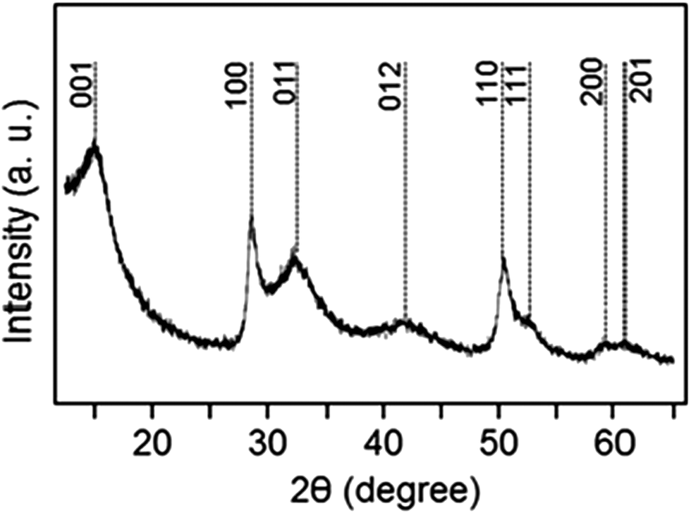 | ||
| Fig. 1 An XRD pattern of the produced electrode material. The peaks of tin sulfide are indexed according to the standard diffraction pattern of the hexagonal SnS2 phase. | ||
The results of the electron microscopy characterization are shown in Fig. 2. According to the scanning electron microscopy (SEM) image (Fig. 2a), a collection of crumbled nanosheets can be observed in the sample, confirming its two-dimensional nature. SEM and bright-field scanning transmission electron microscopy (STEM) images of the same individual SnS2–rGO sheet are presented in Fig. 2b and c. Apart from the bending-thickness contrast in the specimen, additional contrast, originating from the SnS2 coating, is visible in the STEM image. A diffraction pattern (Fig. 2d) consists of polycrystalline rings that can be indexed to the SnS2 phase (standard diffraction file # 01-083-1705). The rings are continuous, without separate bright spots, indicating the small size of SnS2 crystallites on the surface of rGO. An energy-filtered image is shown in Fig. 2e, and the distribution of the graphene oxide nanosheets is depicted using the green color (the contrast is stronger in the wrinkles due to the accumulation of dense carbon). The distribution of sulfur on the surface is shown with the red color. The sulfur coating is continuous, without individual particles visible. Considering the resolution of this mapping technique (1–2 nm), this is consistent with the assumption that a very dense coating of small nanoparticles exists on the surface. Indeed, as revealed by a high angle annular dark-field (HAADF) STEM image (Fig. 2f), tin-containing nanoparticles with sizes of a few nm (a brighter contrast from Sn as a heavier element) exist on the surface. Additional SEM, transmission electron microscopy (TEM) and STEM images of SnS2–rGO can be found in the ESI† (Fig. S2 and S3).
 | ||
| Fig. 2 TEM data for SnS2–rGO: (a) SEM image of an area in the sample; (b and c) SEM and STEM images of an individual SnS2-coated sheet of rGO; (d) selected area diffraction pattern; (e) energy-filtered TEM image (color scheme: red – sulfur, green – carbon); and (f) HAADF STEM image to visualize SnS2 nanoparticles (brighter contrast from tin) on the surface of rGO. | ||
To evaluate SnS2–rGO electrodes in potassium cells, electrochemical tests were carried out in two-terminal half cells with potassium metal as a counter electrode. The selected charge–discharge profiles recorded at 25 mA g−1 are shown in Fig. 3a–c. The initial discharge capacity is around 630 mA h g−1 and the first charge capacity is 355 mA h g−1. The Coulombic efficiency improves in the subsequent cycles: e.g., the discharge and charge capacities are 363 and 340 mA h g−1 in the third cycle, and 342 and 312 mA h g−1 in the tenth cycle. The cyclic voltammetry curves for a SnS2–rGO electrode are shown in the ESI† (Fig. S4). The electrochemical activity of the SnS2–rGO material is on average well above 0 V vs. K/K+, a behavior quite different from that of graphite in potassium cells that exhibits plateaus at low potentials with respect to potassium. It has been previously suggested that low potentials on the graphitic or hard carbon anodes (with respect to the corresponding alkali metal) in lithium and sodium-ion batteries may lead to safety risks under certain conditions due to the metal plating. The anodes operating at higher average potentials vs. the corresponding metal are potentially interesting as they allow eliminating this issue. The SnS2-based system appears to be an example of such an anode in potassium cells.
 | ||
| Fig. 3 Electrochemical characterization of SnS2–rGO material in potassium cells: (a–c) charge–discharge curves in the first, third and tenth cycles at a current rate of 25 mA g−1; (d) cyclic stability at the same current rate; (e) charge–discharge profiles in the fifth cycle obtained for cells cycled at various current rates (25 mA g−1–2 A g−1); and (f) the corresponding plot of reversible capacity as a function of the current rate. | ||
In order to probe the potassium storage mechanism, we attempted XRD analysis of the electrodes stopped at 0.01 V vs. K/K+ in the first discharge and at 2 V vs. K/K+ in the first charge of potassium half-cells (Fig. S6, ESI†). The XRD patterns collected from electrodes extracted from three cells are shown in each instance. Subtle XRD peaks were visible in the XRD patterns of the electrodes discharged to 0.01 V (Fig. S6, left-hand side column, ESI†); however, the intensities were extremely weak due to the severe nanocrystallinity of the sample. In such a situation, it is difficult to assign the XRD peaks to phases reliably. After careful consideration, we were able to establish that the positions of the peaks in the 25–35° range may fit with the expected positions of the strong peaks for KSn and K2S6 phases. However, some of the other peaks for these phases were not observed, and the assignment of XRD peaks is preliminary at this stage. We propose that a more detailed study using bulk, large size SnS2 crystals (in order to obtain clear, easy-to-interpret XRD patterns) needs to be performed in the future to confirm the mechanism for the material. We also observed broadened XRD peaks in the 50–70° range but were not able to assign those to any known phase. Sharp peaks with strong intensities observed in the patterns originate from the copper foil and XRD sample holder. The XRD patterns of the electrodes charged back to 2 V vs. K/K+ (Fig. S6, right-hand side column, ESI†) do not display any detectable XRD signatures (except the strong peaks from the Cu foil and sample holder), suggesting that amorphization of the active compounds in the electrode takes place upon charging the half-cell. On the basis of these preliminary observations, it may be possible that a variation of the sequential conversion and alloying–dealloying mechanism proposed, for example, for lithium cells22 is in play here; however, further detailed studies will be required to verify that. To evaluate the possibility of such a mechanism on a preliminary level, we may correlate the level of capacity in this work with the level of capacity recorded for the same material previously in other types of cells. Studies of the electrochemical reactivity of SnS2–rGO with lithium and sodium have been conducted by the groups of Prikhodchenko and Lev,27,32 and capacities of 1027 and 610 mA h g−1, respectively, have been observed. Much lower capacities in sodium and potassium cells indicate that the exact operating charge storage mechanism of SnS2 in both cells is likely to be different from the mechanism in lithium cells.
The cyclic stability of the SnS2–rGO electrodes is shown in Fig. 3d. In a standard electrolyte of 0.75 KPF6 in a mixture of ethylene carbonate (EC) and diethyl carbonate (DEC), the electrode retains an attractive capacity of more than 280 mA g−1 (in excess of the theoretical capacity of graphite) for the first 25 cycles. The capacity, however, starts to decay subsequently (longer cycling data are shown in Fig. S5, ESI†). This is in contrast to the behaviour of the same electrode in sodium cells with an optimized electrolyte (containing fluoroethylene carbonate (FEC)), where a stable capacity of about 600 mA h g−1 was observed. Indeed, FEC has been identified as a useful additive to standard sodium-ion battery electrolytes, capable of improving the cyclic stabilities of various electrode materials.33–35 To check the applicability of the FEC additive in potassium cells, we conducted a cyclic stability test of the SnS2–rGO electrode in the same electrolyte after adding 3 vol% FEC to the formulation (the data are in Fig. S5, ESI†). Surprisingly, the cyclic behavior is inferior to the cyclic stability in the standard, unmodified electrolyte. These results indicate that the function of electrolyte additives typical for more established lithium or sodium cells may be different in the new potassium-ion batteries. Indeed, Komaba et al.36 also studied the influence of the FEC additive on the cyclic stability of graphitic anodes in potassium cells. Similarly, an addition of the FEC to the electrolyte formulation led to the deterioration of the cyclic performance. It may be concluded that the role of the FEC additive is different in sodium and potassium cells. Another electrolyte additive may be more effective in the potassium cells to improve the cyclic stability of the electrodes.
A set of coin cells was used to test the rate capability of the composite. The mass loading was controlled in the 0.8–0.9 mg cm−2 range for each electrode. The cells were set to charge and discharge at a fixed current in the 25 mA g−1–2 A g−1 range. Fig. 3e shows the capacities and charge–discharge profiles for the cells at various currents (the data are from the fifth cycles). As it follows from Fig. 3f, the rate capability of the SnS2–rGO electrodes is reasonable, with reversible capacity (that is, the capacity measured upon charging a half-cell) of about 120 mA h g−1 still remaining at a high current of 2 A g−1.
The obtained electrochemical data demonstrate a new class of high capacity anodes for potassium-ion batteries. This class includes metal sulfides, and the first example of SnS2 material deposited on reduced graphene oxide is explored here. A significant capacity of 350 mA h g−1 is measured, which is in excess of the theoretical capacity of graphite (278 mA h g−1) in potassium cells and is superior to many reported materials. E.g., hard and soft carbons have demonstrated slightly inferior capacity to that of graphite.15,17 A relatively limited capacity (∼250 mA h g−1) has been reported in Sb–carbon composites (although the proposed theoretical capacity is quite high, 660 mA h g−1).20 Comparable capacity levels (∼385 mA h g−1) have been demonstrated by the Sn4P3-based electrodes.21 In this context, the studied sulphide–rGO system demonstrates an attractive capacity and opens the door for high capacity sulfide materials and their composites to be explored as potential materials for potassium-ion batteries.
In summary, a SnS2–rGO composite material was evaluated as a possible anode material for potassium-ion batteries. Structural studies demonstrate that the active component is in the form of a hexagonal SnS2 phase with possible negligible impurities of SnO2 and elemental sulfur. The SnS2 nanoparticles have an anisotropic morphology of platelets with the reduced crystal thickness along the [001] direction. The nanoparticles are well dispersed on the nanosheets of rGO. The material demonstrates an attractive capacity of about 350 mA h g−1, exceeding the capacity of graphite. A high capacity (above 250 mA h g−1) is retained for the first 30 cycles but capacity decay is observed afterwards. Future studies are required to optimize the cyclic stability. Intriguingly, it is observed that the addition of FEC beneficial for sodium cells does not improve the cyclic stability and, in fact, has an opposite effect. This study reveals a new type of high capacity potassium-ion battery anode based on sulfides and will stimulate the development of non-graphitic anode materials.
This work was supported by the Russian Science Foundation (grant 16-13-00110) and carried out with the support from the Deakin Advanced Characterization Facility. Financial support from Deakin International Postgraduate Scholarship is also acknowledged.
References
- V. Palomares, P. Serras, I. Villaluenga, K. B. Hueso, J. Carretero-Gonzalez and T. Rojo, Energy Environ. Sci., 2012, 5, 5884 CAS
.
- H. Ibrahim, A. Ilinca and J. Perron, Renew. Sustainable Energy Rev., 2008, 12, 1221 CrossRef CAS
-
D. Linden and T. B. Reddy, Handbook of Batteries, McGraw-Hill, 2002 Search PubMed
-
D. Berndt and D. Spahrbier, Ullmann's Encyclopedia of Industrial Chemistry, Batteries, Wiley-VCH Verlag GmbH & Co. KGaA, 2000 Search PubMed
- F. Gschwind, G. Rodriguez-Garcia, D. J. S. Sandbeck, A. Gross, M. Weil, M. Fichtner and N. Hörmann, J. Fluorine Chem., 2016, 182, 76 CrossRef CAS
- X. Zhao, P. Gao, Z. Zhao-Karger, M. Fichtner and X. Shen, ACS Appl. Mater. Interfaces, 2014, 14, 10997 Search PubMed
-
D. R. Lide, CRC Handbook of Chemistry and Physics: Special Student Edition, CRC Press, 77th edn, 1996 Search PubMed
- A. Eftekhari, Z. Jian and X. Ji, ACS Appl. Mater. Interfaces, 2017, 9, 4404 CAS
- A. Eftekhari, J. Power Sources, 2004, 126, 221 CrossRef CAS
- C. D. Wessells, S. V. Peddada, R. A. Huggins and Y. Cui, Nano Lett., 2011, 11, 5421 CrossRef CAS PubMed
- N. Recham, G. Rousse, M. T. Sougrati, J. N. Chotard, C. Frayret, S. Mariyappan, B. C. Melot, J. C. Jumas and J. M. Tarascon, Chem. Mater., 2012, 24, 4363 CrossRef CAS
- V. Mathew, S. Kim, J. Kang, J. Gim, J. Song, J. P. Baboo, W. Park, D. Ahn, J. Han, L. Gu, Y. Wang, Y. S. Hu, Y. K. Sun and J. Kim, NPG Asia Mater., 2014, 6, e138 CrossRef CAS
- X. Wang, X. Xu, C. Niu, J. Meng, M. Huang, X. Liu, Z. Liu and L. Mai, Nano Lett., 2017, 17, 544 CrossRef CAS PubMed
- S. Komaba, T. Hasegawa, M. Dahbi and K. Kubota, Electrochem. Commun., 2015, 60, 172 CrossRef CAS
- Z. Jian, W. Luo and X. Ji, J. Am. Chem. Soc., 2015, 137, 11566 CrossRef CAS PubMed
- W. Luo, J. Wan, B. Ozdemir, W. Bao, Y. Chen, J. Dai, H. Lin, Y. Xu, F. Gu, V. Barone and L. Hu, Nano Lett., 2015, 15, 7671 CrossRef CAS PubMed
- Z. Jian, Z. Xing, C. Bommier, Z. Li and X. Ji, Adv. Energy Mater., 2016, 6, 1501874 CrossRef
- B. Kishore, V. G and N. Munichandraiah, J. Electrochem. Soc., 2016, 163, A2551 CrossRef CAS
- I. Sultana, T. Ramireddy, M. M. Rahman, Y. Chen and A. M. Glushenkov, Chem. Commun., 2016, 52, 9279 RSC
- W. D. McCulloch, X. Ren, M. Yu, Z. Huang and Y. Wu, ACS Appl. Mater. Interfaces, 2015, 7, 26158 CAS
- W. Zhang, J. Mao, S. Li, Z. Chen and Z. Guo, J. Am Chem. Soc., 2017, 139, 3316 CrossRef CAS PubMed
- Y. Zhao, L. P. Wang, M. T. Sougrati, Z. Feng, Y. Leconte, A. Fisher, M. Srinivasan and Z. Xu, Adv. Energy Mater., 2017, 1601424 CrossRef
- S. Li, J. Zheng, Z. Hu, S. Zuo, Z. Wu, P. Yan and F. Pan, RSC Adv., 2015, 5, 72857 RSC
- D. D. Vaughn, O. D. Hentz, S. Chen, D. Wang and R. E. Schaak, Chem. Commun., 2012, 48, 5608 RSC
- Y. Li, J. P. Tu, X. H. Huang, H. M. Wu and Y. F. Yuan, Electrochem. Commun., 2007, 9, 49 CrossRef CAS
- X. Ren, Q. Zhao, W. D. McCulloch and Y. Wu, Nano Res., 2017, 10, 1313 CrossRef CAS
- P. V. Prikhodchenko, D. Y. W. Yu, S. K. Batabyal, V. Uvarov, J. Gun, S. Sladkevich, A. A. Mikhaylov, A. G. Medvedev and O. Lev, J. Mater. Chem. A, 2014, 2, 8431 CAS
- L. Zhuo, Y. Wu, L. Wang, Y. Yu, X. Zhang and F. Zhao, RSC Adv., 2012, 2, 5084 RSC
- J. Ma, D. Lei, L. Mei, X. Duan, Q. Li, T. Wang and W. Zheng, Cryst. Eng. Commun., 2012, 14, 832 RSC
- J. W. Seo, J. T. Jang, S. W. Park, C. Kim, B. Park and J. Cheon, Adv. Mater., 2008, 20, 4269 CrossRef CAS
- S. Liu, X. Lu, J. Xie, G. Cao, T. Zhu and X. Zhao, ACS Appl. Mater. Interfaces, 2013, 5, 1588 CAS
-
P. V. Prikhodchenko, Thesis (Doctor of Chemical Sciences), Kurnakov Institute of General and Inorganic Chemistry, RAS, Moscow, 2014
- S. Komaba, T. Ishikawa, N. Yabuuchi, W. Murata, A. Ito and Y. Ohsawa, ACS Appl. Mater. Interfaces, 2011, 3, 4165 CAS
- J. Qian, X. Wu, Y. Cao, X. Ai and H. Yang, Angew. Chem., Int. Ed., 2013, 52, 4633 CrossRef CAS PubMed
- D. Y. W. Yu, P. V. Prikhodchenko, C. W. Mason, S. K. Batabyal, J. Gun, S. Sladkevich, A. G. Medvedev and O. Lev, Nat. Commun., 2013, 4, 2922 Search PubMed
- X. Bie, K. Kubota, T. Hosaka, K. Chihara and S. Komaba, J. Mater. Chem. A., 2017, 5, 4325 CAS
Footnote |
| † Electronic supplementary information (ESI) available: Experimental details, XPS data, additional TEM characterization, cyclic voltammetry and cyclic stability data, and XRD patterns of the electrodes discharged and charged in potassium half-cells. See DOI: 10.1039/c7cc03998k |
| This journal is © The Royal Society of Chemistry 2017 |