Advancements in the stability of perovskite solar cells: degradation mechanisms and improvement approaches

Bobo Li, Yafang Li, Chaoyue Zheng, Deqing Gao* and Wei Huang*
Jiangsu National Synergistic Innovation Centre for Advanced Materials (SICAM), Key Laboratory of Flexible Electronics (KLOFE), Institute of Advanced Materials (IAM), Nanjing Tech University (NanjingTech), 30 South Puzhu Road, Nanjing 211816, P. R. China. E-mail: iamdqgao@njtech.edu.cn; iamwhuang@njtech.edu.cn

Received 22nd December 2015 , Accepted 7th April 2016

First published on 8th April 2016


Abstract

Recently, organic metal halide perovskites have emerged as one of the most promising photoactive materials in the field of photovoltaics. Over the past six years, the efficiency of perovskite solar cells (PSCs) has increased from initially 3.8% to 20.8% through the optimization of perovskite film fabrication and device architecture. However, perovskites suffer inherent instability and degrade rapidly under different exposures (water, oxygen, UV-light irradiation and high temperature), limiting their further application to commercialization. Herein, several studies have been carried out to resolve this problem to some extent. In this paper, possible degradation mechanisms are summarized in order to help us understand the process of perovskite decomposition. Moreover, we also systematically outline and classify the approaches to improve the long-term stability of perovskite devices.

Introduction

Over the past six years, hybrid organic–inorganic metal halide perovskites, a class of promising materials in the field of photovoltaics and light-emitting diodes, have been rapidly developed. Their chemical formula is ABX3 (A is an organic cation, such as methylammonium or formamidinium; B is a divalent metal ion, such as lead or tin; X is a halide ion, such as iodine, bromine or chlorine), and the crystal belongs to the octahedral structure where A cations occupy the lattice corners, B ions occupy the interstitial site and X anions occupy lattice faces.1–3 As a type of semiconductor, perovskites own many superior properties, including a broad light absorption spectrum, tunable band gap, long charge carrier diffusion and low-cost preparation technology.4–9

The initial application of organometal halide perovskites in solar cells was reported by Miyasaka et al. in 2009.10 They utilized CH3NH3PbI3 and CH3NH3PbBr3 as visible-light sensitizes for photovoltaic cells, yielding a power conversion efficiency (PCE) of 3.81% and 3.13%, respectively. Subsequently, a great many of researches were devoted to the development of perovskite solar cells. Up to now, the highest efficiency of 20.8% has been achieved by Hagfeldt and co-workers.11 Such rapid and tremendous improvement is mainly benefited by the optimization of film deposition techniques and device structural composition. It is well-known that the compact and uniform perovskite films with high crystallization are crucial for device performance and reproducibility. One-step spin-coating process, two-step sequential deposition and vapor deposition are the commonly used methods to fabricate high-quality perovskite films.12–14 Device architectures which can be divided into two main types, conventional (TiO2 (ETL)/perovskite/organic semiconductors (HTL)) and inverted (PEDOT:PSS (hole transport layer, HTL)/perovskite/PCBM (electron transport layer, ETL)) structure, are also important to obtain high efficient PSCs.15,16 Of course, various substitutes for the above-mentioned charge transfer materials have been investigated to get more advantageous structure.

In view of the breakthrough in device efficiency which has been acquired, practical application seems to be considered. However, perovskites present the nature of instability and undergo extremely fast degradation under ambient conditions, thus limiting their commercialization. As demonstrated in previous reports, perovskite is sensitive to H2O and O2, which can induce the irreversible formation of PbI2, CH3NH2 and HI.1 The decomposition would also occur under continuous light irradiation, which is mainly caused by non-stoichiometry induced defects in n-type TiO2.17,18 In addition, perovskites cannot endure high temperature.19 To improve the stability of perovskite device, much efforts have been made. This review is focused on the degradation mechanisms under different conditions as well as various methods to mitigate the instability of PSCs. We aim to provide a brief summary but will emphasize the key studies and results.

Degradation mechanisms in PSCs

Moisture and oxygen

Moisture has been reported as a double-edged sword in the performance of PSCs. On the one hand, moisture has a positive effect on perovskite solar cell technology. As reported, controlled humidity condition can enhance the reconstruction process by partially dissolving the reactant species in the perovskite film formation and cause grain boundary movement through inducing grain boundary to creep and merging adjacent grains together, which result in the formation of large-sized crystals and reduced pinholes in the perovskite film.20,21 Moreover, moisture can trigger nucleation and crystallization of perovskite phase.22 A small amount of H2O in the PbI2 precursor solution is also beneficial for the formation of smooth and dense perovskite film.23

On the other hand, H2O molecular is well-known as the chief culprit for damaging the integrity of perovskite films. Many researchers have been devoted to seeking the degradation mechanisms and various decomposition processes have been reported. Wang et al. have performed the measurements of UV-Vis absorption and XRD on the CH3NH3PbI3 film before and after degradation in air with 60% relative humidity under sunlight for 18 hours (35 °C). After degradation, the absorption peaks of perovskite (530–800 nm) decreased sharply, remaining the absorption peaks of PbI2 which is less than 520 nm in the spectrum. In XRD spectra, the diffraction peaks of CH3NH3PbI3 disappeared and new peaks assigned to PbI2 appeared after aging. According to these results, they proposed the possible degradation reactions of perovskite when exposed to moisture, which are listed as follows:24,25

 
image file: c5ra27424a-t1.tif(1)
 
CH3NH3I (aq) ↔ CH3NH2 (aq) + HI (aq) (2)
 
4HI (aq) + O2 ↔ 2I2 (s) + 2H2O (3)
 
image file: c5ra27424a-t2.tif(4)

They thought that CH3NH3PbI3 is inclined to hydrolyze in the presence of water, resulting in the formation of PbI2 and CH3NH3I (MAI) solution. Subsequently, CH3NH3I solution is easy to decompose into CH3NH2 solution and HI solution. Additionally, HI will react with oxygen molecular to generate I2 and H2O. Photochemical reaction of HI can occur under light irradiation, as shown in reaction (4).

However, several groups have reported some different degradation reactions in perovskite film under humidity condition. Kelly et al. used in situ grazing incidence X-ray diffraction (GIXD) to monitor the degradation process.26 They found that the formation of hydrated (CH3NH3)4PbI6·2H2O intermediate containing isolated PbI64− octahedral was the initial step in the perovskite decomposition process under 80% humidity exposure. This can be evidenced in GIXRD patterns. The appearance of new diffraction spots (q ≈ 5 and 7 nm−1) after exposure to moisture which were assigned to neither CH3NH3PbI3 nor PbI2 implied the formation of new intermediate crystalline phase. Similar results can be exhibited in powder XRD spectrum through the measurement of CH3NH3PbI3 powder before and after the addition of a little H2O. They also found that the intermediate phase was unstable in ambient atmosphere and partially converted to CH3NH3PbI3 reversibly over several tens of minutes. Further decomposition would proceed through converting CH3NH3I to CH3NH2 and HI, leaving PbI2 crystal phase as the ultimate product of the reaction. Another study from Kamat and co-workers has demonstrated the similar experimental results. They also found that an intermediate hydrated phase is existed in the water-inducing degradation of perovskite.27 Apart from experimental data, relevant theoretical simulations are also reported. Mosconi et al. have investigated the interface between water molecule and perovskite and analyzed the effect of hydration on the perovskite electronic structure by using ab initio molecule dynamics simulations. In their report, CH3NH3I-terminated group tends to be soluble, containing the processes of the nucleophilic substitution of dangling I ions by water molecule and the solvation of CH3NH3+ cations, which was driven by the interaction between Pb atoms and H2O molecules. The PbI2-terminated surface is less sensitive to water. The formation of [PbI2(H2O)4] and [PbI(H2O)5]+ complexes through the infiltration of a H2O molecule into PbI2-terminated group is the initial step in the formation of hydrated intermediate.28

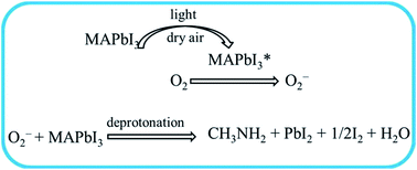
Oxygen molecules can also cause the decomposition of perovskite materials. Haque and co-workers have reported that the combination of molecular oxygen and light can lead to the degradation of CH3NH3PbI3 perovskite. Through the measurements of perovskite film after degradation under illumination and dry atmosphere, they concluded that photoexcited electrons in CH3NH3PbI3 would react with molecular oxygen to form superoxide (O2) when the perovskite is exposed to light and dry air. Subsequently, the decomposition of perovskite is initiated by the reaction between superoxide and methylammonium cation, thus leading to the formation of PbI2, iodine and water molecule.29 This process can be identified by using Nuclear Magnetic Resonance (NMR), XRD and Raman spectroscopy. The generated by-product of water would then participate in the further degradation. The possible reactions are shown in Fig. 1.


image file: c5ra27424a-f1.tif
Fig. 1 The degradation reactions of perovskite in the presence of molecular oxygen.

UV light illumination

As reported, high efficiency of PSCs can be easily obtained by using compact or mesoporous TiO2 as electron transfer layer. However, ultraviolet light can seriously influence the stability of the TiO2-based cells. Snaith and co-workers have investigated the degradation process of TiO2-based solar cells under full spectrum simulated (100 mW cm−2) sunlight illumination at 40 °C.30 They found that the non-encapsulated device without UV filtration was more stable than the encapsulated ones in an inert atmosphere. Simultaneous charge extraction and transient absorption spectroscopy (TAS) were performed on TiO2-based perovskite devices to investigate the reasons for degradation. The charge collection efficiency of sealed cell showed deterioration after exposure to laser, which was more serious than that for unsealed ones. Herein, they proposed the degradation mechanism which is related to the surface chemistry of TiO2, as shown in Fig. 2. Many oxygen vacancies are existence in the TiO2, especially at the surface, which can adsorb molecule oxygen in ambient atmosphere to form charge transfer complex (O2–Ti4+) (Fig. 2(a)). The excited electron–hole pair is generated on TiO2 upon UV light exposure. The hole in the valence band can recombine with the electron at the oxygen adsorption site, thus leading to the release of the absorbed oxygen. Then a free electron is left in the conduction band. Meanwhile, the unfilled oxygen vacancy site, which served as deep surface traps site, is left on the TiO2 surface (Fig. 2(b) and (c)). These remaining electrons will recombine with the excess holes in the p-doped transfer layer (Fig. 2(d)). As the increase of recombination of electrons and holes and trap sites, the device performance will be influenced.
image file: c5ra27424a-f2.tif
Fig. 2 Schematic diagram of proposed degradation mechanism upon UV-light irradiation. Source: reprinted with permission from ref. 30. Copyright © 2013, rights managed by Nature Publishing Group.

Ito et al. have found that the perovskite device (FTO/TiO2/CH3NH3PbI3/CuSCN/Au) deteriorated rapidly under light exposure in the absence of surface blocking layer between TiO2 and perovskite. They speculated that degradation upon light irradiation could occur at the interface of TiO2/perovskite accordingly.31 The possible degradation reactions are the following eqn (5)–(7):

 
2I ↔ I2 + 2e (5)
 
3CH3NH3+ ↔ 3CH3NH2↑ + 3H+ (6)
 
I + I2 + 3H+ + 2e ↔ 3HI↑ (7)

Firstly, TiO2 is easy to extract electrons from iodide anion (I), thus damaging the perovskite crystal, leading to the generation of I2 (eqn (5)). Then the equilibrium of eqn (6) tends to shift to the right side because the perovskite structure is no more integrated. At last, the extracted electrons can return to form I2 and the reaction (7) is triggered in the presence of I and H+, resulting in the formation of volatile HI. Along with continuous elimination of H+ and evaporation of CH3NH2, eqn (6) was driven forward. Apart from the reaction equations, Fig. 3(a) also vividly exhibits the whole degradation process.


image file: c5ra27424a-f3.tif
Fig. 3 Sketch maps of perovskite degradation against light exposure in the structure of (a) TiO2/CH3NH3PbI3 and (b) TiO2/Sb2S3/CH3NH3PbI3. Source: reprinted with permission from ref. 31. Copyright © 2014, American Chemical Society.

Temperature

Another factor to be considered is the temperature dependence of the perovskite structure. Although thermal treatment is necessary in the formation of perovskite crystals, obvious structural transformation of CH3NH3PbI3 during annealing at 85 °C was detected by Conings and co-workers.32 The intrinsic thermal instability was evaluated through the investigation of the changes in morphology, optical absorption, electrical and chemical properties of perovskite film which was fabricated on ITO/TiO2 planar substrate. These measurements were carried out under N2, O2 and ambient atmosphere (50% relative humidity) in the dark for 24 h (at 85 °C), respectively. The morphology was hardly recognizable when compared with its pristine feature after treatment in ambient condition. Obvious morphological changes also appeared in the samples which were heated in N2 and O2. The structural changes were further confirmed by using conductive atomic force microscopy (C-AFM), as shown in Fig. 4. The differences in topography images (left column) are consistence with SEM images. The increasing dark areas in current maps (right column) after heating were due to the fact that the conductive perovskite was converted to poorly-conducting PbI2 crystals, thus leading to the reduction of electrical current. The existence of PbI2 can be verified in XRD patterns. These results indicated that the degradation reaction initiates at the temperature at 85 °C and the degradation rate is dependent on the surrounding atmosphere.
image file: c5ra27424a-f4.tif
Fig. 4 AFM images (left column) and C-AFM images (right column) at V = 0.5 V of perovskite films when exposure to different atmospheres at 85 °C for 24 hours. The percentages on the C-AFM images represent the proportion of light area which makes contributions to the measured current. Source: reprinted with permission from ref. 32. Copyright © 2015 WILEY-VCH Verlag GmbH & Co. KGaA, Weinheim.

Philippe and co-workers demonstrated the thermal stability through the evolution of the I/Pb and N/Pb ratios by using photoelectron spectroscopy (PES).33 In order to exclude the influence of X-ray beam, it was switched off during the process of heating and cooling for the perovskite films. The samples were firstly measured at room temperature and then they were continuously heated to 100 °C for 20 min and 200 °C for 20 min. As can be seen in Fig. 5 (marked “①”), both the I/Pb and N/Pb ratios declined linearly with the rise of temperature. After 200 °C, the I/Pb and N/Pb ratios dropped to 2.0 and 0, which indicating the complete conversion to PbI2. Moreover, Katz et al. have demonstrated that the degradation by photoinduced decomposition is thermally accelerated.34 The degradation is initiated and enhanced by a combined effect of light and heat during concentrated sunlight exposure and is possibly related to penetration of ambient species to the encapsulated samples.


image file: c5ra27424a-f5.tif
Fig. 5 Evolution of the I/Pb (red circle) and N/Pb (black square) ratios upon the increase of heating temperature. Source: reprinted with permission from ref. 33. Copyright © 2015, American Chemical Society.

Recently Leong et al. investigated the relationship between the performance parameters in perovskite devices and temperature.35 They prepared nominally non-degraded mesoporous PSCs and the temperature-dependent measurements were carried out in the range of 80–360 K. The PCE firstly increased (T < 330 K) and then decreased (T = 330–360 K) upon the change of temperature.

The temperature dependence of Voc can divide into two stages. In the range of low-temperature (T < 250 K), Voc almost remained in the level of 1.0–1.1 V. In the range of high-temperature (220 < T < 360 K), Voc declined linearly with increasing temperature.

Methods to improve the stability of PSCs

Perovskite materials

As represented above, the primary instability factor originates from the lattice structure of CH3NH3PbI3 perovskite. In order to obtain stable perovskite materials, multiple studies have been developed. One of the most effective methods is to fabricate mixed-halide perovskites. Seok and co-workers employed the chemically tuned CH3NH3Pb(I1−xBrx)3 as the photoactive layer in PSCs.6 The Pb–Br bond is more difficult to break because it is stronger and shorter than Pb–I bond. The substitution of larger I atoms with smaller Br atoms in perovskite would reduce lattice constant and transfer the tetragonal phase to cubic phase.34,36 By using various content of Br addition, the devices exhibited different degradative behavior. The devices containing CH3NH3Pb(I1−xBrx)3 (x = 0.2, 0.29), at high Br ratio, were less sensitive to 55% humidity than the CH3NH3Pb(I1−xBrx)3 (x = 0, 0.06)-based solar cells which suffered serious degradation in PCE after 20 days of aging tests. Similarly, two research groups have applied mixed CH3NH3PbI2Br perovskites in mesoporous PSCs to prolong the lifetime of devices.37,38 Recently, Yu et al. reported a new approach to obtain CH3NH3PbI3−xBrx perovskite through the halide exchange between CH3NH3Br solution and two-step spin-coated CH3NH3PbI3 film.39 The CH3NH3PbI3−xBrx-based device yielded PCE of 14.25% and remained 93% of its initial PCE under air condition for 2 weeks without encapsulation, which was more stable than the CH3NH3PbI3-based device.

Even though many researchers have proved that the incorporation of Br atom can stabilize the structure of perovskite materials, it is noteworthy that light-induced and reversible transformations also existed in mixed (CH3NH3)Pb(BrxI1−x)3 perovskite, which was reported by McGehee's group.40 They observed the structural changes upon light soaking in x = 0.6 perovskite film by using photocurrent spectroscopy and XRD measurements. The transformation of absorption from band-edge states and splitting of all diffraction peaks in XRD pattern implied that the formation of minority iodide-enriched phases ((MA)Pb(Br0.2I0.8)3). After the treatment in the dark for 5 min, these changes disappeared and the spectra returned to their origin states. They thought that photoexcitation may cause halide segregation, thus leading to the coexistence of iodide-enriched minority and bromide-enriched majority phases.

Apart from Br-doping, pseudohalogen thiocyanite (SCN) is known to possess similar ionic radius (∼217 pm) to I (∼220 pm), which is expected to be incorporated into perovskite crystal.41 In our previous work, we have fabricated the mixed CH3NH3PbI3−x(SCN)x perovskite film by adding a small amount of Pb(SCN)2 (5 wt%) into PbI2 precursor solution through two-step sequential deposition. The device based on CH3NH3PbI3−x(SCN)x film exhibited better stability than the CH3NH3PbI3-based cell after exposure to continuous illumination (AM 1.5G sunlight irradiation) for one hour in air condition.42 Xu et al. used the mixture of Pb(SCN)2 and CH3NH3I precursor solution to prepare CH3NH3Pb(SCN)2I perovskite film, in which two iodides were replaced by two thiocyanate ions. They found that the CH3NH3Pb(SCN)2I films showed enhanced moisture resistance than pure CH3NH3PbI3 films after exposure to 95% relative humidity condition for over 4 hours.43 The reason may be that the lone pairs of electrons from S and N atoms in SCN would produce strong interaction with the Pb ions, thus stabilizing the crystal structure of perovskite.

Another available route is to change the organic cation. Although the organic cation does not mainly determine the electronic properties, its improper size can cause the distortion of the whole lattice which in turn affects electronic band structure.1 As reported, formamidinium (FA, NH2CH[double bond, length as m-dash]NH2+) with slightly larger ionic radius can be used to substitute methylammonium (MA, CH3NH3+). Interestingly, some groups have found that the FAPbI3 perovskite exhibits superior thermal stability compared with MAPbI3 perovskite. Snaith et al. have tested the stability of these two films at high temperature (150 °C) in air. After exposure for 0.5 h, it was observed that the former kept stable without discolouration, while the latter faded quickly.44 The stabilization mechanism can be attributed to the increasing number of hydrogen bonds between the hydrogen atoms of the ammonium cations and iodide ions in the inorganic cage.45

Additionally, Wang et al. used trivalent bismuth (Bi) to substitute toxic Pb in perovskite material.46 The non-toxic and stable (CH3NH3)3Bi2I9 (MBI) perovskite was prepared through a low-temperature process. The MBI film did not show any obvious degradation when exposure to ambient air for 40 days, which was reflected in the XRD patterns.

Moreover, two-dimensional (2D) layered hybrid perovskite, (PEA)2(MA)n−1[PbnI3n+1] (n represents the number of Pb–I sheets in each inorganic layer) (PEA = C6H5(CH2)2NH3+) (Fig. 6(a)), was used as an absorber in perovskite solar cells by Karunadasa and co-workers.47 The 2D perovskite mainly contains the n = 3 phase. However, small amounts of n = 1 and n = 2 phases were also detected in the 2D structure which can be identified in the absorption spectrum, suggesting minority defect layers were unavoidable. The 2D perovskite film with high-quality was deposited through one-step spin-coating under ambient humidity levels without high-temperature annealing. To compare the moisture resistance with three-dimensional (3D) (MA)[PbI3], powder X-ray diffraction (PXRD) was characterized, as shown in Fig. 6(b). After exposure to 52% relative humidity for 46 days, the crystal structure of (PEA)2(MA)2[Pb3I10] almost did not show any obvious changes, but (MA)[PbI3] completely converted to PbI2. The 2D layered structure in (PEA)2(MA)2[Pb3I10] can be evolved from 3D analogue by slicing along specific crystallographic planes. Such structure is beneficial for the formation of high-quality film, thus leading to superior stability.


image file: c5ra27424a-f6.tif
Fig. 6 (a) Crystal structure of the 3D perovskite (MA)[PbI3] and the 2D layered perovskite (PEA)2(MA)2[Pb3I10]. (b) PXRD patterns of (PEA)2(MA)2[Pb3I10] and (MA)[PbI3] films after exposure to 52% relative humidity. Source: adapted with permission from ref. 47. Copyright © 2014 WILEY-VCH Verlag GmbH & Co. KGaA, Weinheim.

Recently, Grätzel et al. employed bifunctional alkylphosphonic acid ω-ammonium cations (ABPA) as the crosslinking agent between adjacent CH3NH3PbI3 crystals, as shown in Fig. 7, thus enhancing their cohesion.48 Meanwhile, such additive also acted as a growth-controlling and surface-passivating agent, resulting in uniform morphology and high crystalline. The addition of ABPA in the perovskite structure showed greatly enhanced stability under various test conditions. Firstly, the PCE of ABPA-modified perovskite-based solar cells without encapsulation maintained at 14% when exposure to 55% humidity condition for one week, while the pristine CH3NH3PbI3-based device decayed from 7% to 1% during the same period. Secondly, after continuous light soaking at 45 °C for 7 days, the encapsulated CH3NH3PbI3-ABPA-based and pristine devices retain 90% and 70% of their initial performance, respectively. Thirdly, the ABPA-modified perovskite device also exhibited better thermal tolerance when measured under 85 °C for 350 h in the dark compared to the pristine solar cell.


image file: c5ra27424a-f7.tif
Fig. 7 Schematic illustration of connection between two neighbouring grains with alkylphosphonic acid ω-ammonium as crosslinking agent. Source: reprinted with permission from ref. 48. Copyright © 2015, rights managed by Nature Publishing Group.

Preparation technology

The quality of perovskite film will not only directly determine the photovoltaic performance, but also influence the stability of the device. Perovskite films with poor morphology will degrade quickly in ambient condition. Most recently, various film fabrication methods have been explored to obtain highly stable and efficient perovskite devices.

In 2013, Burschka et al. have reported a two-step sequential deposition method to prepare perovskite films with well-controllable morphology. The corresponding device could remain about 80% of its initial performance after exposure to light soaking (light intensity ∼ 100 mW cm−2) at 45 °C for over 500 h.49

From then on, many groups have tried to explore different solutions to improve the quality of perovskite films. For example, the incorporation of Cl through different approaches in the perovskite film formation can influence long-term stability. Shirai et al. have prepared the mixed CH3NH3PbI3−xClx perovskite films through the interdiffusion process (two-step deposition method) by adding appropriate CH3NH3Cl (5–20 wt%) to CH3NH3I precursor solution.50 The presence of Cl can optimize the crystallization processes and enhance the degree of crystallinity. The CH3NH3PbI3−xClx film also exhibited improved morphology with uniform, smooth and pinhole-free surface coverage. They compared the photostability of CH3NH3PbI3 and CH3NH3PbI3−xClx-based devices under continuous illumination (1 sun) within two hours. A gradual decrease in Jsc was found in CH3NH3PbI3 device, whereas no degradation was found in the CH3NH3PbI3−xClx device. Moreover, the CH3NH3PbI3−xClx-based devices with encapsulation were exposed to ambient conditions and they revealed enhanced stability by maintaining over 90% of their initial PCE after a period of two months. Similarly, the multilayered CH3NH3PbI3−xClx perovskite films prepared from the layer-by-layer approach which combined the repeated processes of thermal evaporation of PbCl2 and dip of CH3NH3I solution, could achieve homogeneous morphology, thus slowing down the degradation progress and reducing leak current.51 Besides, the device preparation using PbCl2 as lead source presented higher stability than the device fabricated from non-Cl-containing Pb(CH3CH2COO)2 precursor.52

Choy et al. prepared the perovskite film via one-step deposition technology by using the mixture of 3CH3NH3I[thin space (1/6-em)]:[thin space (1/6-em)]PbCl2 precursor solution.53 However, they found that the residual CH3NH3Cl byproduct during the deposition process could influence the crystalline quality and accelerate the degradation of perovskite films. The explanation is that the existence of CH3NH3Cl would absorb water from air which is detrimental for the stability. By using vacuum-assisted thermal annealing technology, the byproduct could be completely removed, leading to pore-free and well-crystallized perovskite films. Through the test of stability, the film containing CH3NH3Cl residue, which was thermal annealed in the glove box, degraded quickly within 2 hours after exposure to a relative 45–50% humidity condition. Differently, the perovskite without CH3NH3Cl residue could sustain up to one month at the same aging condition.

Later, Choy's group developed another effective method to obtain smooth, highly-crystalline, pin-hole free and PbI2 residue-free CH3NH3PbI3 films through the optimization of two-step sequential deposition in planar PSCs.54 The improved processes included the addition of 4-tert-butylpyridine (TBP) dopant into PbI2 precursor solution and the proper increase of MAI concentrations. The dopant can facilitate the formation of self-assembled porous PbI2 layer (SAP-PbI2), which is beneficial for the complete conversion to perovskite, thus forming the highly-quality films. The SAP-PbI2-based device without PbI2 residue exhibited superior stability than the conventional PbI2-based device with PbI2 after exposure in ambient air (45–65% humidity, room temperature) for about one month.

Besides, the use of additive can improve the quality of perovskite films. For example, Cheng et al. added ethylammonium iodide (EAI) into mixed PbCl2[thin space (1/6-em)]:[thin space (1/6-em)]MAI perovskite precursor solution and monitored the stability of the corresponding device toward thermal treating (temperature: 65 °C, N2 atmosphere in the dark).55 They found that the device using EAI retained over 80% and 60% of its initial PCE after a period of 360 h and 580 h, respectively. In contrast, for the normal device, the values decreased to 80% and 60% only after 40 and 200 hours, respectively.

Furthermore, the perovskite films prepared using non-solution technology, such as chemical vapor deposition and blade-coating process, were also demonstrated to exhibit superior stability.56,57

Device structure

Apart from perovskite materials, other components in device architecture would also accelerate the decomposition of perovskite devices. So developing more stable device structural composition is non-ignorable. In the following sections, we will summarize the studies about the improvement in charge transport layers, electrodes and interfacial layers, respectively.
HTM. The commonly used hole transport material (HTM) in inverted PSCs, PEDOT:PSS, can damage ITO electrode and activate the decomposition of CH3NH3PbI3 due to its acidic and hygroscopic nature, thus leading to relatively low stability of the PSCs. Several groups have attempted to find a solution for the issue. As a typical example, poly[2,6-(4,4-bis-potassiumbutanylsulfonate-4H-cyclopenta-[2,1-b;3,4-b′]-dithiophene)-alt-4,7-(2,1,3-benzothiadiazole)] (CPE-K), a pH-neutral organic semiconductor, was considered as an alternative to PEDOT:PSS.58 The use of CPE-K enables the formation of uniform perovskite films with complete surface coverage and the device can not only achieve higher efficiency (over 12%), but also show improved stability in air when compared with the PEDOT:PSS based-PSC.

Inorganic p-type semiconductors can also be used to substitutes for PEDOT:PSS. Among them, NiOx seems to be an attractive HTM candidate due to its wide bandgap, well aligned with perovskite layer, good environment stability and low cost. Jen et al. have employed Cu-doped NiOx as the hole transfer layer in inverted perovskite device. The addition of Cu dopant can improve electrical conductivity. The device with Cu[thin space (1/6-em)]:[thin space (1/6-em)]NiOx can maintain 90% of its initial PCE after storage in air for 240 h, while the efficiency of the PEDOT:PSS-based device decreased to <50% after exposure in air for 144 h.59 Subsequently, they also prepared the surface-nanostructured NiOx film through room-temperature solution process, which can be applied in flexible perovskite solar cells. The eventual NiOx-based device (glass or PET/ITO/NiOx/CH3NH3PbI3/C60/bis-C60/Ag) showed good air stability.60 In addition, Kim and co-workers have utilized neutral reduced grapheme oxide (RGO) as HTM in PSC.61 Compared with acidic PEDOT:PSS-based solar cells, the RGO-based devices showed superior stability after exposure to ambient condition for over 140 h. The main reason may attribute to the few oxygen functionalities of the RGO surface and the passivation ability against oxygen and moisture.

Another route to mitigate the corrosion is to suppress the acid of the PEDOT:PSS to some extent. Liao et al. prepared the PEDOT:PSS–GeO2 hybrid films by mixing the GeO2 aqueous solution into the PEDOT:PSS dipersion.62 GeO2 tends to be near-alkaline in aqueous solution due to its week hydrolysis (GeO2 + 2H2O = Ge(OH)4), thus increasing the pH value of PEDOT:PSS–GeO2 composite. When exposure to air, the efficiency of pristine PEDOT:PSS-based cell decreased to half of its initial value only after 14 h, whereas the device with PEDOT:PSS–GeO2 sustained as long as 26 h before the reach of half-efficiency.

In the conventional PSCs, 2,2′,7,7′-tetrakis (N,N-di-p-methoxyphenyl-amine)-9,9′-spirobifluorene (spiro-OMeTAD) is the frequently-used HTM. However, in order to achieve high charge mobility and electrical conductivity of spiro-OMeTAD, the hygroscopic p-type dopant lithium-bis(trifluoromethane)sulfonamide (Li-TFSI) is prevalently used as an additive, which would in turn induce the degradation of the perovskite film under humidity condition. Li-TFSI salt can also promote the oxidative reaction between spiro-OMeTAD and oxygen. Therefore, exploring stable additives or novel HTMs without Li-TFSI is necessary. McGehee et al. utilized a dicationic salt of spiro-OMeTAD, spiro(TFSI)2, as a substitute for Li-TFSI doped spiro-OMeTAD in PSC.63 The device with spiro(TFSI)2 can not only achieve the same level of efficiency with the conventional spiro-OMeTAD-based solar cell, but also exhibit excellent stability when subjected to continuous illumination in an inert atmosphere for 10 min. Lin et al. reported the combination of highly conductive reduced graphene oxide (RGO) and spiro-OMeTAD as the hole transport layer and tested the stability of unsealed devices with RGO-spiro and LI-TFSI doped spiro.64 It was observed that the PCE of the former only dropped by 15% after storage in air for 500 h, whereas the latter showed a 65% PCE drop at the same aging time. Besides, the stable organic salts, such as AgTFSI and IrCp*Cl(PyPyz)[TFSI], can be used as effective p-type additive in spiro-OMeTAD to avoid the existence of deliquescent lithium salt, thus improving the device stability.65,66

Excluding the influence of additives, the pinholes existing in the spiro-OMeTAD films are beneficial for the inward diffusion of water and oxygen molecules as well as the outward diffusion of MAI or HI volatile steam, leading to the decomposition of perovskite films. So Qi et al. have demonstrated to fabricate pinhole-free spiro-OMeTAD film by changing the chlorobenzene solvent to chloroform in the procedure of dissolving the HTM powder.67 The pinhole-free device remained 50% of its initial PCE after aging in air (42% relative humidity) for 100 hours, while the efficiency of pinhole cell dropped to 0% only after 12 h. Additionally, they fabricated the pinhole-free HTM by incorporating the n-type dopant (decamethylcobaltocene, DMC) and p-type dopant (F4-TNCQ) in intrinsic spiro-OMeTAD. The doped device even exhibited higher efficiency than its initial value under exposure in air for 35 days, while the un-doped device remained only 50% after 300 h.68

Furthermore, various substitutes for spiro-OMeTAD have been developed, including p-type polymeric semiconductors, small-molecular HTMs and inorganic hole-semiconductors. Among them, poly(3-hexylthiophene) (P3HT) with high hole mobility and good stability is the most representative polymeric HTM candidate. Meng et al. employed the large π-conjugated graphdiyne as a dopant in P3HT hole transfer layer and the corresponding device exhibits good stability when stored at room temperature for half a month.69 The superior stability is mainly attributed to the hydrophobic nature of P3HT and graphdiyne. Similarly, Snaith et al. utilized the composite P3HT/single-walled carbon nanotubes (SWNTs)–PMMA structure as HTM to improve thermal and moisture stability of the device.70 Another polymeric HTM, hydrophobic poly[2,5-bis(2-decyldodecyl)-pyrrolo[3,4-c]pyrrole-1,4(2H,5H)-dione-(E)-1,2-di(2,2′-bithiophen-5-yl)-ethene] (PDPPDBTE) which can prevent water permeation into the perovskite film was reported by Taiho Park's group.71 The corresponding device could remain stable over 1000 hours under humid condition.

Yang and co-workers introduced a small-molecular HTM, tetrathiafulvalene derivative (TTF), in perovskite solar cells. The highest occupied molecule orbital (HOMO) level (−5.0 eV vs. vacuum level) of TTF matches well with the valence band level (−5.4 eV vs. vacuum level) of CH3NH3PbI3, which can yield a comparable efficiency with traditional spiro-OMeTAD based device.72 More importantly, the hydrophobic alkyl chains in TTF molecules can greatly improve the stability by two fold when stored in air condition with 40% humidity. Ko et al. applied two types of star-shaped triphenylamine derivatives, named TPA-MeOPh and FA-MeOPh, in perovskite solar cells.73,74 After long-term light soaking test over 250 h (one sun illumination), the corresponding devices exhibited good stability in relative to the standard spiro-OMeTAD. Meng et al. used 2TPA-n-DP (TPA = 4,4′-((1E,1′E,3E,3′E)-[1,1′-biphenyl]-4,4′-diylbis(buta-1,3-diene-4,1-diyl)); DP = bis(N,N-di-p-tolylaniline)) as HTMs in perovskite devices, which exhibited long-term stability under dry and dark condition for 900 h.75 Xiao's group reported the highly stable PSC with the HTM of hydrophobic oligothiophene derivative abbreviated to DR3TBDTT. High efficiency can be achieved by adding a small amount of polymethylsiloxane (PDMS).76 The stability of DR3TBDTT + PDMS based cells outperformed the device with Li-TFSI doped HTM under 50% relative humidity for 3 days. In addition, 7-(9,9′-spirobifluorene-2-yl)-N-(7-(9,9′-spirobifluorene-2-yl)-9,9-dioctyl-9H-fluoren-2-yl)-N-(4-(9H-carbazol-9-yl)phenyl)-9,9-dioctyl-9H-fluoren-2-amine (CzPAF-SBF) containing several alkyl chains which can improve hydrophobicity, has been recently used as HTMs in PSCs.77 The CzPAF-SBF based devices exhibited not only a maximum efficiency of 17.21%, but also good stability after the storage in ambient air (humidity ≈ 28%) for 500 h without encapsulation. Both the PCE and stability are superior to the spiro-OMeTAD-based PSCs.

Inorganic p-type semiconductors often possess high chemical stability, hole mobility and low cost compared with organic materials, which are used not only in inverted PSCs as mentioned above, but also as candidates for spiro-OMeTAD. For instance, Kamat et al. have applied CuI as HTM in the conventional PSCs and the corresponding devices were more stable under AM 1.5G illumination (100 mV cm−2) in ambient air than the conventional spiro-OMeTAD-based solar cells.78

ETM. Electron transport materials, such as TiO2 and PCBM which are commonly used in the conventional and inverted devices respectively, can also trigger the device degradation due to their intrinsic defects. As mentioned in the section of Degradation mechanisms in PSCs, the existence of electron traps in n-type TiO2 semiconductor is one of the limiting factors in device performance and long-term stability. Snaith et al. have investigated the effect of doping TiO2 photoanode with aluminum on the performance and stability enhancement in the perovskite solar cells.17 From Fig. 8, we can see that two adjacent tri-valent titanium with an oxygen vacancy are replaced by two stable Al(III) ions, leading to the decrease of non-stoichiometric oxygen-induced defects. It is beneficial for passivating electronic trap sites in the bulk or on the surface of TiO2 and increasing electron conductivity, thus improving the efficiency and stability upon UV exposure of devices. Even so, insufficiencies still exist in such device construction. For example, the newly-doped Al electron states would make the conduction band (CB) of TiO2 upward shift, thus leading to the loss of short-circuit current. Herein, another metal, neodymium (Nd) was considered to be doped in mesoporous TiO2 films in their subsequent work.79 Nd electron states almost have no effect on the CB of TiO2 and Nd doping can also reduce the deep trap density in the TiO2 lattice. The device based on 0.3% Nd-doped TiO2 reached a stabilized PCE of 18.2% and showed better lifetime when compared with undoped device.
image file: c5ra27424a-f8.tif
Fig. 8 Schematic illustration of (a) bare TiO2 and (b) Al-doped TiO2. Source: adapted with permission from ref. 17. Copyright © 2014 WILEY-VCH Verlag GmbH & Co. KGaA, Weinheim.

Brown et al. have demonstrated the performance and long-time stability of various device structures, including planar device with a compact TiO2 layer, mesoporous devices with bare and TiCl4-treated TiO2 nanorods scaffold.80 After exposure to <35% humidity condition at room temperature as long as 55 days, both the two types of mesoporous devices remained more stable than planar architecture. As seen in Fig. 9, the PCE of planar device dropped from initial value of 12.1% to 0.6%, whereas both of the mesoporous ones maintained most of their initial efficiency. The increased stability of device employing mesoporous scaffold may be due to the improved crystallinity and homogeneous morphology of perovskite grown on TiO2 nanorods. Haque et al. found that the presence of mesoporous (mp) TiO2 is crucial for improving the immunity to environment in the PSCs, which was realized by rapidly extracting the photo-electron from perovskite.81 They compared the stability of devices based on the mp-TiO2/MAPbI3/spiro-OMeTAD, insulating mp-Al2O3/MAPbI3/spiro-OMeTAD and MAPbI3/spiro-OMeTAD bilayer. The former decreased only 25% in PCE after exposure to dry air and light for 72 h, while the mp-Al2O3 and bilayer devices exhibited rapid degradation.


image file: c5ra27424a-f9.tif
Fig. 9 The changes in photovoltaic parameters of planar, NRs and TiCl4-NRs devices during 55 days under <35% humidity and room temperature. Source: reprinted with permission from ref. 80. Copyright © 2015 Elsevier B.V. All rights reserved.

Vinogradov and co-workers reported that the perovskite solar cells using TiO2–MOF composite (TiO2–Mil-125) as ETL exhibited durable stability.82 Besides, n-type ZnO nanorods and fullerene C60 were used as the substitutes for TiO2 in perovskite device, resulting in the enhancement of long-term stability.83,84

The inverted devices using PCBM as ETM were reported to be sensitive to ambient condition. The reasons may be due to the followings: (1) PCBM can absorb oxygen/water, thus damaging itself and perovskite layer. (2) Al or Ag electrode can easily diffuse through PCBM layer and react with perovskite, which is due to that PCBM layer is thin and incompletely covered on the perovskite film. Therefore, Yang and co-workers used metal oxide, n-type ZnO nanoparticles and p-type NiOx, as the hole and electron transport materials to replace PEDOT:PSS and PCBM in inverted device structure, respectively.85 That can simultaneously reduce the negative effects of PEDOT:PSS and PCBM. They tested the air stability of these two unencapsulated devices (ITO/PEDOT:PSS/perovskite/PCBM/Al and ITO/NiOx/perovskite/ZnO/Al) under 30–50% humidity condition (T = 25 °C). The efficiency of device based on organic transfer layer dropped closely to zero only after 5 days. However, the metal-oxide-based device kept stable and its PCE was maintained up to 2 months (Fig. 10).


image file: c5ra27424a-f10.tif
Fig. 10 (a) Schematic diagram of metal-oxide-based device. (b) Normalized PCE of the devices (ITO/NiOx/perovskite/ZnO/Al (red line) and ITO/PEDOT:PSS/perovskite/PCBM/Al (black line)) which measured under 30–50% humidity condition (T = 25 °C). Source: adapted with permission from ref. 85. Copyright © 2015, rights managed by Nature Publishing Group.
Electrode. Ag and Au are commonly used as the electrodes in PSCs. However, Ag is easily corroded through the contact with perovskite film, leading to the formation of silver halide. Au is relatively stable, but the price is high. Over the past several years, carbon electrode employed in HTM-free PSC has been a hot research direction for its low cost, high conductivity and appropriate energy level. Moreover, carbon electrode possesses more hydrophobic surface, which is beneficial to prevent the infiltration of H2O under moisture conditions. This work was initiated by Han's group in Wuhan, China. They firstly prepared TiO2/perovskite heterojunction solar cells with carbon electrode, which exhibited high stability and efficiency of 6.64%.86 Later, they introduced the mixed-cation (5-AVA)x(MA)1−xPbI3 perovskite in carbon-based HTM-free device. Such cells achieved a high efficiency of 12.8% and remained stable after exposure to simulated sunlight (AM 1.5) over 1008 h in ambient air condition.87 Subsequently, they investigated the stability of the encapsulated similar triple-layer PSCs structure under real outdoor conditions in Jeddah, Saudi Arabia and elevated temperatures, respectively. The results are shown in Fig. 11. We can see that the performance remained stable after exposing outdoor over one week and the PCE even increased slightly higher than its initial value.88 The measurements of high-temperature stability were executed at 80–85 °C under ambient air. The device was sealed during the test. After 90 days, these parameters (Voc, Jsc, FF and PCE) were almost unchanged.
image file: c5ra27424a-f11.tif
Fig. 11 The evolutions of photovoltaic parameters in the encapsulated PSC (a) during outdoor aging in Jeddah, Saudi Arabia and (b) under ambient air condition at 80–85 °C. Source: adapted with permission from ref. 88. Copyright © 2015 WILEY-VCH Verlag GmbH & Co. KGaA, Weinheim.

Other groups have also made contributions to the development of carbon-based HTM-free PSCs. Ma et al. reported the TiO2/CH3NH3PbI3 heterojunction solar cells based on low-temperature processed carbon electrode. Through the aging test, the devices without encapsulation exhibited excellent stability over 2000 h when stored in air condition in the dark.89 Similarly, the commercial carbon paste-based HTM-free perovskite devices fabricated by Yang et al. can be stable over 800 h when stored in ambient condition at room temperature.90 These exciting results provide a good prospect for future practical applications of perovskite photovoltaic.

Interfacial layer. It has been reported that charge recombination and corrosion can be retarded to some extent by inserting interfacial layers in the structure of perovskite device, thus improving the photovoltaic performance and stability. For instance, Sb2S3 has been used as the surface blocking layer between TiO2 and CH3NH3PbI3 perovskite, which can passivate the photocatalytic effect of TiO2 and inhibit charge recombination. As shown in Fig. 3(b), Sb2S3 can suppress the extraction of electrons at the surface of TiO2, avoiding the reaction of I/I2 (eqn (1)). With Sb2S3 layer, the CH3NH3PbI3 film can be stabilized under light exposure for 12 h.31

The dodecyltrimethoxysilane (C12-silane) layer which possesses insulating and hydrophobic nature was self-assembled onto the perovskite/HTM interface. The interlayer can not only reduce charge recombination, but also improve moisture resistance. With the interfacial modification, the perovskite surface would change to be hydrophobic and the modified device retained 85% of its initial efficiency under ambient condition for 600 h.91 Zheng et al. also introduced hydrophobic pentafluorobenzenethiol (HS-C6F5) at the perovskite/HTM interface to inhibit the infiltration of H2O molecules into the perovskite film, thus leading to enhanced stability of PSCs upon air and light illumination.92 A thin Al2O3 layer can act as a good barrier against oxygen and moisture, too. So some researchers deposited the Al2O3 films above the perovskite layer to realize the long-term stability of the devices.93,94

The buffer layer embedded between an electrode and charge transport layer is also crucial to achieve highly efficient and stable PSCs. Zhou et al. investigated the influence of C60 buffer layer, which was inserted between PCBM and LiF, on the stability of PSCs.95 When stored in the glove-box, the triple PCBM/C60/LiF-based device remained 95% of its initial efficiency after 14 days, while the device without C60 buffer layer decreased to 60% after only 10 days. Besides, TiO2 or ZnO interlayer inserted between Al electrode and PCBM electron transport layer can not only protect PCBM from reacting with Al cathode, but also block the inward penetration of H2O into perovskite fillm.96,97 Moreover, Wang et al. introduced a p-type a:CuAlO2 layer between PEDOT:PSS and ITO electrode, which can simultaneously improve the device efficiency and stability.98 Such improvements are contributed to the decent conductivity, chemical stability of CuAlO2 and reduction of corrosion to the ITO electrode from acid PEDOT:PSS. Similarly, Su and co-workers introduced a MoO3 buffer layer between ITO electrode and PEDOT:PSS.99 The MoO3/PEDOT:PSS bilayer structure was used as HTM and the device exhibited slow degradation under ambient conditions for 10 days.

Device encapsulation

Apart from the modification of perovskite materials and the optimization of the device structure, device encapsulation technology is an effective method to improve the stability of perovskite solar cells. For example, Yong et al. introduced the hydrophobic polymer Teflon onto the top side of the perovskite device which can prevent the water infiltration from air.100 The Teflon-treated PSC showed a negligible change in efficiency after storage in ambient atmosphere for one month, while the PCE of non-encapsulated device dropped from initial 11.3% to 6.3% in the same aging time. Weerasinghe et al. have demonstrated various encapsulated architectures in flexible PSCS (PET/IZO/TiO2/CH3NH3PbI3/spiro-OMeTAD/Au) with plastic barrier encapsulant films, including ‘partially’-encapsulated cells in which electrical contacts directly connect with the devices and ‘completely’-encapsulated cells in which thin copper wires are soldered to form electrical connections (Fig. 12(a) and (b)).101 They performed the stability tests under ambient condition for a long storage time. After 400 h, both the two encapsulated cells exhibited significant improvement in device stability compared with non-encapsulate ones. However, the ‘partially’-encapsulated cell only remained 80% of their initial efficiency after 400 h and then degraded quickly in the next 100 hours (Fig. 12(c)). This phenomenon was due to that water molecules can penetrated into the device through unprotected edges of PET substrate and adhesive layers. Additionally, Al2O3 film was reported as an encapsulation layer through atomic layer deposition technology, resulting in significantly improvement of ambient stability.102
image file: c5ra27424a-f12.tif
Fig. 12 Schematic views of the (a) ‘partially’ encapsulated and (b) ‘completely’ encapsulated devices. (c) Normalized PCE of the devices after storage in ambient conditions. Source: adapted with permission from ref. 101. Copyright © 2015 Elsevier Ltd. All rights reserved.

Stability of perovskite in other applications

Perovskites can also be applied other fields, such as light-emitting devices, photodetectors and lasing.103–105 Mathews et al. have demonstrated the low-temperature solution-processed CH3NH3PbI3 perovskite films for lasing and assessed the photostability by monitoring the change in amplified spontaneous emission (ASE) intensity under laser irradiation (1 kHz repetition rate, room temperature).105 The intensity remained stable with a standard deviation of 0.2% after continuous irradiation for 26 h. Thus low ASE threshold was ascribed to the low bulk defect density and high crystallinity in CH3NH3PbI3 films.

Conclusions and outlook

In conclusion, along with the tremendous progress in efficiency of perovskite solar cells, researches on the issue of instability, including degradation process upon different exposures and the methods to improve device stability, have attracted much more attention. Up to now, the possible degradation reactions of perovskite materials against water, oxygen, UV-light irradiation and high temperature were proposed. In addition, the optimization of perovskite crystal and composition, perovskite film deposition, modification or substitution of charge transport layers and electrodes, interface engineering and encapsulation technology were taken into consideration for enhancing the immunity to ambient conditions.

Although multiple studies focused on this topic have been demonstrated, several problems should still be further explored. For example, the underlying degradation mechanisms, especially thermal decomposition, should be fundamentally and systematically investigated. Furthermore, the corresponding conditions of stability test have not yet been unified, resulting in different even completely opposite results. Therefore, the creation of standards of measurements, such as relative humidity, highest temperature, oxygen content, intensity of UV-light and maintainable time of efficiency, is urgent in the next few years.

Acknowledgements

This work was supported by National Key Basic Research Program of China under grant No. 2015CB932200 (Deqing Gao and Wei Huang).

Notes and references

  1. Q. Chen, N. De Marco, Y. Yang, T.-B. Song, C.-C. Chen, H. X. Zhao, Z. R. Hong, H. P. Zhou and Y. Yang, Nano Today, 2015, 10, 355–396 CrossRef CAS.
  2. P. Gao, M. Grätzel and M. K. Nazeeruddin, Energy Environ. Sci., 2014, 7, 2448–2463 CAS.
  3. T. Baikie, Y. Fang, J. M. Kadro, M. Schreyer, F. Wei, S. G. Mhaisalkar, M. Graetzel and T. J. White, J. Mater. Chem. A, 2013, 1, 5628–5641 CAS.
  4. L. Etgar, P. Gao, Z. S. Xue, Q. Peng, A. K. Chandiran, B. Liu, M. K. Nazeeruddin and M. Grätzel, J. Am. Chem. Soc., 2012, 134, 17396–17399 CrossRef CAS PubMed.
  5. N. J. Jeon, J. H. Noh, Y. C. Kim, W. S. Yang, S. Ryu and S. I. Seok, Nat. Mater., 2014, 13, 897–903 CrossRef CAS PubMed.
  6. J. H. Noh, S. H. Im, J. H. Heo, T. N. Mandal and S. I. Seok, Nano Lett., 2013, 13, 1764–1769 CrossRef CAS PubMed.
  7. S. A. Kulkarni, T. Baikie, P. P. Boix, N. Yantara, N. Mathews and S. Mhaisalkar, J. Mater. Chem. A, 2014, 2, 9221–9225 CAS.
  8. S. D. Stranks, G. E. Eperon, G. Grancini, C. Menelaou, M. J. P. Alcocer, T. Leijtens, L. M. Herz, A. Petrozza and H. J. Snaith, Science, 2013, 342, 341–344 CrossRef CAS PubMed.
  9. G. C. Xing, N. Mathews, S. Y. Sun, S. S. Lim, Y. M. Lam, M. Grätzel, S. Mhaisalkar and T. C. Sum, Science, 2013, 342, 344–347 CrossRef CAS PubMed.
  10. A. Kojima, K. Teshima, Y. Shirai and T. Miyasaka, J. Am. Chem. Soc., 2009, 131, 6050–6051 CrossRef CAS PubMed.
  11. D. Q. Bi, W. Tress, M. I. Dar, P. Gao, J. S. Luo, C. Renevier, K. Schenk, A. Abate, F. Giordano, J.-P. C. Baena, J.-D. Decoppet, S. M. Zakeeruddin, M. K. Nazeeruddin, M. Grätzel and A. Hagfeldt, Sci. Adv., 2016, 2, e1501170 Search PubMed.
  12. P. W. Liang, C. Y. Liao, C. C. Chueh, F. Zuo, S. T. Williams, X. K. Xin, J. J. Lin and A. K. Y. Jen, Adv. Mater., 2014, 26, 3748–3754 CrossRef CAS PubMed.
  13. J.-H. Im, I.-H. Jang, N. Pellet, M. Grätzel and N.-G. Park, Nat. Nanotechnol., 2014, 9, 927–932 CrossRef CAS PubMed.
  14. M. Z. Liu, M. B. Johnston and H. J. Snaith, Nature, 2013, 501, 395–398 CrossRef CAS PubMed.
  15. J. B. You, Z. R. Hong, Y. M. Yang, Q. Chen, M. Cai, T.-B. Song, C.-C. Chen, S. R. Lu, Y. S. Liu, H. P. Zhou and Y. Yang, ACS Nano, 2014, 8, 1674–1680 CrossRef CAS PubMed.
  16. M. M. Lee, J. Teuscher, T. Miyasaka, T. N. Murakami and H. J. Snaith, Science, 2012, 338, 643–647 CrossRef CAS PubMed.
  17. S. K. Pathak, A. Abate, P. Ruckdeschel, B. Roose, K. C. Gödel, Y. Vaynzof, A. Santhala, S.-I. Watanabe, D. J. Hollman, N. Noel, A. Sepe, U. Wiesner, R. Friend, H. J. Snaith and U. Steiner, Adv. Funct. Mater., 2014, 24, 6046–6055 CrossRef CAS.
  18. Y. G. Rong, L. F. Liu, A. Y. Mei, X. Li and H. W. Han, Adv. Energy Mater., 2015, 5, 1501066 Search PubMed.
  19. M. He, D. J. Zheng, M. Y. Wang, C. J. Lin and Z. Q. Lin, J. Mater. Chem. A, 2014, 2, 5994–6003 CAS.
  20. H. P. Zhou, Q. Chen, G. Li, S. Luo, T. B. Song, H. S. Duan, Z. R. Hong, J. B. You, Y. S. Liu and Y. Yang, Science, 2014, 345, 542–546 CrossRef CAS PubMed.
  21. J. B. You, Y. Yang, Z. R. Hong, T.-B. Song, L. Meng, Y. S. Liu, C. Y. Jiang, H. P. Zhou, W.-H. Chang, G. Li and Y. Yang, Appl. Phys. Lett., 2014, 105, 183902 CrossRef.
  22. K. K. Bass, R. E. McAnally, S. Zhou, P. I. Djurovich, M. E. Thompson and B. C. Melot, Chem. Commun., 2014, 50, 15819–15822 RSC.
  23. C.-G. Wu, C.-H. Chiang, Z.-L. Tseng, M. K. Nazeeruddin, A. Hagfeldt and M. Grätzel, Energy Environ. Sci., 2015, 8, 2725–2733 CAS.
  24. G. D. Niu, X. D. Guo and L. D. Wang, J. Mater. Chem. A, 2015, 3, 8970–8980 CAS.
  25. G. D. Niu, W. Z. Li, F. Q. Meng, L. D. Wang, H. P. Dong and Y. Qiu, J. Mater. Chem. A, 2014, 2, 705–710 CAS.
  26. J. L. Yang, B. D. Siempelkamp, D. Y. Liu and T. L. Kelly, ACS Nano, 2015, 9, 1955–1963 CrossRef CAS PubMed.
  27. J. A. Christians, P. A. Miranda Herrera and P. V. Kamat, J. Am. Chem. Soc., 2015, 137, 1530–1538 CrossRef CAS PubMed.
  28. E. Mosconi, J. M. Azpiroz and F. De Angelis, Chem. Mater., 2015, 27, 4885–4892 CrossRef CAS.
  29. N. Aristidou, I. Sanchez-Molina, T. Chotchuangchutchaval, M. Brown, L. Martinez, T. Rath and S. A. Haque, Angew. Chem., Int. Ed., 2015, 54, 8208–8212 CrossRef CAS PubMed.
  30. T. Leijtens, G. E. Eperon, S. Pathak, A. Abate, M. M. Lee and H. J. Snaith, Nat. Commun., 2013, 4, 2885 Search PubMed.
  31. S. Ito, S. Tanaka, K. Manabe and H. Nishino, J. Phys. Chem. C, 2014, 118, 16995–17000 CAS.
  32. B. Conings, J. Drijkoningen, N. Gauquelin, A. Babayigit, J. D'Haen, L. D'Olieslaeger, A. Ethirajan, J. Verbeeck, J. Manca, E. Mosconi, F. D. Angelis and H.-G. Boyen, Adv. Energy Mater., 2015, 5, 1500477 Search PubMed.
  33. B. Philippe, B.-W. Park, R. Lindblad, J. Oscarsson, S. Ahmadi, E. M. J. Johansson and H. Rensmo, Chem. Mater., 2015, 27, 1720–1731 CrossRef CAS.
  34. R. K. Misra, S. Aharon, B. Li, D. Mogilyansky, I. Visoly-Fisher, L. Etgar and E. A. Katz, J. Phys. Chem. Lett., 2015, 6, 326–330 CrossRef CAS PubMed.
  35. W. L. Leong, Z. E. Ooi, D. Sabba, C. Yi, S. M. Zakeeruddin, M. Graetzel, J. M. Gordon, E. A. Katz and N. Mathews, Adv. Mater., 2016, 28, 2439–2445 CrossRef CAS PubMed.
  36. M. Benavides-Garcia and K. Balasubramanian, J. Chem. Phys., 1994, 100, 2821–2830 CrossRef CAS.
  37. K. Cao, J. Cui, H. Zhang, H. Li, J. K. Song, Y. Shen, Y. B. Cheng and M. K. Wang, J. Mater. Chem. A, 2015, 3, 9116–9122 CAS.
  38. M. Zhang, M. Q. Lyu, H. Yu, J. H. Yun, Q. Wang and L. Z. Wang, Chem.–Eur. J., 2015, 21, 434–439 CrossRef CAS PubMed.
  39. W. D. Zhu, C. X. Bao, F. M. Li, T. Yu, H. Gao, Y. Yi, J. Yang, G. Fu, X. X. Zhou and Z. G. Zou, Nano Energy, 2016, 19, 17–26 CrossRef CAS.
  40. E. T. Hoke, D. J. Slotcavage, E. R. Dohner, A. R. Bowring, H. I. Karunadasa and M. D. McGehee, Chem. Sci., 2015, 6, 613–617 RSC.
  41. A. Halder, R. Chulliyil, A. S. Subbiah, T. Khan, S. Chattoraj, A. Chowdhury and S. K. Sarkar, J. Phys. Chem. Lett., 2015, 6, 3483–3489 CrossRef CAS PubMed.
  42. Y. N. Chen, B. B. Li, W. Huang, D. Q. Gao and Z. Q. Liang, Chem. Commun., 2015, 51, 11997–11999 RSC.
  43. Q. L. Jiang, D. Rebollar, J. Gong, E. L. Piacentino, C. Zheng and T. Xu, Angew. Chem., Int. Ed., 2015, 54, 7617–7620 CrossRef CAS PubMed.
  44. G. E. Eperon, S. D. Stranks, C. Menelaou, M. B. Johnston, L. M. Herz and H. J. Snaith, Energy Environ. Sci., 2014, 7, 982–988 CAS.
  45. A. Binek, F. C. Hanusch, P. Docampo and T. Bein, J. Phys. Chem. Lett., 2015, 6, 1249–1253 CrossRef CAS PubMed.
  46. M. Q. Lyu, J.-H. Yun, M. L. Cai, Y. L. Jiao, P. V. Bernhardt, M. Zhang, Q. Wang, A. J. Du, H. X. Wang, G. Liu and L. Z. Wang, Nano Res., 2016, 9, 692–702 CrossRef CAS.
  47. I. C. Smith, E. T. Hoke, D. Solis-Ibarra, M. D. McGehee and H. I. Karunadasa, Angew. Chem., Int. Ed., 2014, 53, 11232–11235 CrossRef CAS PubMed.
  48. X. Li, M. I. Dar, C. Y. Yi, J. S. Luo, M. Tschumi, S. M. Zakeeruddin, M. K. Nazeeruddin, H. W. Han and M. Grätzel, Nat. Chem., 2015, 7, 703–711 CrossRef CAS PubMed.
  49. J. Burschka, N. Pellet, S. J. Moon, R. H. Baker, P. Gao, M. K. Nazeeruddin and M. Gratzel, Nature, 2013, 499, 316–319 CrossRef CAS PubMed.
  50. N. Tripathi, M. Yanagida, Y. Shirai, T. Masuda, L. Hanb and K. Miyano, J. Mater. Chem. A, 2015, 3, 12081–12088 CAS.
  51. Y. H. Chen, T. Chen and L. M. Dai, Adv. Mater., 2015, 27, 1053–1059 CrossRef CAS PubMed.
  52. F. K. Aldibaja, L. Badia, E. M. Marz, R. S. Sanchez, E. M. Barea and I. M. Sero, J. Mater. Chem. A, 2015, 3, 9194–9200 CAS.
  53. F. X. Xie, D. Zhang, H. M. Su, X. G. Ren, K. S. Wong, M. Grätzel and W. C. H. Choy, ACS Nano, 2015, 9, 639–646 CrossRef CAS PubMed.
  54. H. Zhang, J. Mao, H. X. He, D. Zhang, H. L. Zhu, F. X. Xie, K. S. Wong, M. Grätzel and W. C. H. Choy, Adv. Energy Mater., 2015, 5, 1501354 Search PubMed.
  55. H. L. Hsu, C. C. Chang, C. P. Chen, B. H. Jiang, R. J. Jeng and C. H. Cheng, J. Mater. Chem. A, 2015, 3, 9271–9277 CAS.
  56. P. F. Luo, Z. F. Liu, W. Xia, C. C. Yuan, J. G. Cheng and Y. W. Lu, ACS Appl. Mater. Interfaces, 2015, 7, 2708–2714 CAS.
  57. J. H. Kim, S. T. Williams, N. Cho, C. C. Chueh and A. K. Y. Jen, Adv. Energy Mater., 2015, 5, 1401229 Search PubMed.
  58. H. Choi, C. K. Mai, H. B. Kim, J. Jeong, S. Song, G. C. Bazan, J. Y. Kim and A. J. Heeger, Nat. Commun., 2015, 6, 7348 CrossRef CAS PubMed.
  59. J. H. Kim, P. W. Liang, S. T. Williams, N. Cho, C. C. Chueh, M. S. Glaz, D. S. Ginger and A. K. Y. Jen, Adv. Mater., 2015, 27, 695–701 CrossRef CAS PubMed.
  60. H. Zhang, J. Q. Cheng, F. Lin, H. X. He, J. Mao, K. S. Wong, A. K. Y. Jen and W. C. H. Choy, ACS Nano, 2016, 10, 1503–1511 CrossRef CAS PubMed.
  61. J. S. Yeo, R. Kang, S. Lee, Y. J. Jeon, N. Myoung, C. L. Lee, D. Y. Kim, J. M. Yun, Y. H. Seo, S. S. Kim and S. I. Na, Nano Energy, 2015, 12, 96–104 CrossRef CAS.
  62. Z. K. Wang, M. Li, D. X. Yuan, X. B. Shi, H. Ma and L. S. Liao, ACS Appl. Mater. Interfaces, 2015, 7, 9645–9651 CAS.
  63. W. H. Nguyen, C. D. Bailie, E. L. Unger and M. D. McGehee, J. Am. Chem. Soc., 2014, 136, 10996–11001 CrossRef CAS PubMed.
  64. Q. Luo, Y. Zhang, C. Y. Liu, J. B. Li, N. Wang and H. Lin, J. Mater. Chem. A, 2015, 3, 15996–16004 CAS.
  65. B. Xu, J. Huang, H. Agren, L. Kloo, A. Hagfeldt and L. C. Sun, ChemSusChem, 2014, 7, 3252–3256 CrossRef CAS PubMed.
  66. L. Badia, E. Mas-Marzá, R. S. Sánchez, E. M. Barea, J. Bisquert and I. M. Seró, APL Mater., 2014, 2, 081507 CrossRef.
  67. L. K. Ono, S. R. Raga, M. Remeika, A. J. Winchester, A. Gabe and Y. B. Qi, J. Mater. Chem. A, 2015, 3, 15451–15456 CAS.
  68. M. C. Jung, S. R. Raga, L. K. Ono and Y. B. Qi, Sci. Rep., 2015, 5, 9863 CrossRef CAS PubMed.
  69. J. Y. Xiao, J. J. Shi, H. B. Liu, Y. Z. Xu, S. T. Lv, Y. H. Luo, D. M. Li, Q. B. Meng and Y. L. Li, Adv. Energy Mater., 2015, 5, 1401943 Search PubMed.
  70. S. N. Habisreutinger, T. Leijtens, G. E. Eperon, S. D. Stranks, R. J. Nicholas and H. J. Snaith, Nano lett., 2014, 14, 5561–5568 CrossRef CAS PubMed.
  71. Y. S. Kwon, J. Lim, H. J. Yun, Y. H. Kim and T. Park, Energy Environ. Sci., 2014, 7, 1454–1460 CAS.
  72. J. Liu, Y. Z. Wu, C. J. Qin, X. D. Yang, T. Yasuda, A. Islam, K. Zhang, W. Q. Peng, W. Chen and L. Y. Han, Energy Environ. Sci., 2014, 7, 2963–2967 CAS.
  73. H. Choi, S. Paek, N. Lim, Y. H. Lee, M. K. Nazeeruddin and J. Ko, Chem.–Eur. J., 2014, 20, 10894–10899 CrossRef CAS PubMed.
  74. H. Choi, S. Park, S. Paek, P. Ekanayake, M. K. Nazeeruddin and J. Ko, J. Mater. Chem. A, 2014, 2, 19136–19140 CAS.
  75. L. F. Zhu, J. Y. Xiao, J. J. Shi, J. J. Wang, S. T. Lv, Y. Z. Xu, Y. H. Luo, Y. Xiao, S. R. Wang, Q. B. Meng, X. G. Li and D. M. Li, Nano Res., 2015, 8, 1116–1127 CrossRef CAS.
  76. L. L. Zheng, Y. H. Chung, Y. Z. Ma, L. P. Zhang, L. X. Xiao, Z. J. Chen, S. F. Wang, B. Qu and Q. H. Gong, Chem. Commun., 2014, 50, 11196–11199 RSC.
  77. S. S. Reddy, K. Gunasekar, J. H. Heo, S. H. Im, C. S. Kim, D. H. Kim, J. H. Moon, J. Y. Lee, M. Song and S. H. Jin, Adv. Mater., 2016, 28, 686–693 CrossRef CAS PubMed.
  78. J. A. Christians, R. C. Fung and P. V. Kamat, J. Am. Chem. Soc., 2014, 136, 758–764 CrossRef CAS PubMed.
  79. B. Roose, K. C. Gödel, S. Pathak, A. Sadhanala, J. P. C. Baena, B. D. Wilts, H. J. Snaith, U. Wiesner, M. Grätzel, U. Steiner and A. Abate, Adv. Energy Mater., 2016, 6, 1501868 Search PubMed.
  80. A. Fakharuddin, F. Di Giacomo, I. Ahmed, Q. Wali, T. M. Brown and R. Jose, J. Power Sources, 2015, 283, 61–67 CrossRef CAS.
  81. F. T. F. O'Mahony, Y. H. Lee, C. Jellett, S. Dmitrov, D. T. J. Bryant, J. R. Durrant, B. C. O'Regan, M. Graetzel, M. K. Nazeeruddin and S. A. Haque, J. Mater. Chem. A, 2015, 3, 7219–7223 Search PubMed.
  82. A. V. Vinogradov, H. Z. Hertling, E. H. Hawkins, A. V. Agafonov, G. A. Seisenbaeva, V. G. Kessler and V. V. Vinogradov, Chem. Commun., 2014, 50, 10210–10213 RSC.
  83. D. Bi, G. Boschloo, S. Schwarzmuller, L. Yang, E. M. Johansson and A. Hagfeldt, Nanoscale, 2013, 5, 11686–11691 RSC.
  84. K. Wojciechowski, T. Leijtens, S. Siprova, C. Schlueter, M. T. Horantner, J. T. Wang, C. Z. Li, A. K. Jen, T. L. Lee and H. J. Snaith, J. Phys. Chem. Lett., 2015, 6, 2399–2405 CrossRef CAS PubMed.
  85. J. B. You, L. Meng, T. B. Song, T.-F. Guo, Y. Yang, W.-H. Chang, Z. R. Hong, H. J. Chen, H. P. Zhou, Q. Chen, Y. S. Liu, N. D. Marco and Y. Yang, Nat. Nanotechnol., 2016, 11, 75–81 CrossRef CAS PubMed.
  86. Z. L. Ku, Y. G. Rong, M. Xu, T. F. Liu and H. W. Han, Sci. Rep., 2013, 3, 3132 Search PubMed.
  87. A. Y. Mei, X. Li, L. F. Liu, Z. L. Ku, T. F. Liu, Y. G. Rong, M. Xu, M. Hu, J. Z. Chen, Y. Yang, M. Grätzel and H. W. Han, Science, 2014, 345, 295–298 CrossRef CAS PubMed.
  88. X. Li, M. Tschumi, H. W. Han, S. S. Babkair, R. A. Alzubaydi, A. A. Ansari, S. S. Habib, M. K. Nazeeruddin, S. M. Zakeeruddin and M. Grätzel, Energy Technol., 2015, 3, 551–555 CrossRef CAS.
  89. H. W. Zhou, Y. T. Shi, Q. S. Dong, H. Zhang, Y. J. Xing, K. Wang, Y. Du and T. L. Ma, J. Phys. Chem. Lett., 2014, 5, 3241–3246 CrossRef CAS PubMed.
  90. F. G. Zhang, X. C. Yang, H. X. Wang, M. Cheng, J. H. Zhao and L. C. Sun, ACS Appl. Mater. Interfaces, 2014, 6, 16140–16146 CAS.
  91. J. Zhang, Z. L. Hu, L. K. Huang, G. Q. Yue, J. W. Liu, X. W. Lu, Z. Y. Hu, M. H. Shang, L. Y. Han and Y. J. Zhu, Chem. Commun., 2015, 51, 7047–7050 RSC.
  92. J. Cao, J. Yin, S. F. Yuan, Y. Zhao, J. Li and N. F. Zheng, Nanoscale, 2015, 7, 9443–9447 RSC.
  93. S. Guarnera, A. Abate, W. Zhang, J. M. Foster, G. Richardson, A. Petrozza and H. J. Snaith, J. Phys. Chem. Lett., 2015, 6, 432–437 CrossRef CAS PubMed.
  94. X. Dong, X. Fang, M. H. Lv, B. C. Lin, S. Zhang, J. N. Ding and N. Y. Yuan, J. Mater. Chem. A, 2015, 3, 5360–5367 CAS.
  95. X. D. Liu, H. Yu, L. Yan, Q. Q. Dong, Q. Wan, Y. Zhou, B. Song and Y. F. Li, ACS Appl. Mater. Interfaces, 2015, 7, 6230–6237 CAS.
  96. Y.-Y. Yu, R.-S. Chiang, H.-L. Hsu, C.-C. Yang and C.-P. i. Chen, Nanoscale, 2014, 6, 11403–11410 RSC.
  97. L. Q. Zhang, X. W. Zhang, Z. G. Yin, Q. Jiang, X. Liu, J. H. Meng, Y. Zhao and H. Wang, J. Mater. Chem. A, 2015, 3, 12133–12138 CAS.
  98. F. Igbari, M. Li, Y. Hu, Z.-K. Wang and L.-S. Liao, J. Mater. Chem. A, 2016, 4, 1326–1335 CAS.
  99. F. H. Hou, Z. S. Su, F. M. Jin, X. W. Yan, L. D. Wang, H. F. Zhao, J. Z. Zhu, B. Chu and W. L. Li, Nanoscale, 2015, 7, 9427–9432 RSC.
  100. I. Hwang, I. Jeong, J. Lee, M. J. Ko and K. Yong, ACS Appl. Mater. Interfaces, 2015, 7, 17330–17336 CAS.
  101. H. C. Weerasinghe, Y. Dkhissi, A. D. Scully, R. A. Caruso and Y.-B. Cheng, Nano Energy, 2015, 18, 118–125 CrossRef CAS.
  102. C.-Y. Chang, K.-T. Lee, W.-K. Huang, H.-Y. Siao and Y.-C. Chang, Chem. Mater., 2015, 27, 5122–5130 CrossRef CAS.
  103. J. P. Wang, N. N. Wang, Y. Z. Jin, J. J. Si, Z. K. Tan, H. Du, L. Cheng, X. L. Dai, S. Bai, H. P. He, Z. Z. Ye, M. L. Lai, R. H. Friend and W. Huang, Adv. Mater., 2015, 27, 2311–2316 CrossRef CAS PubMed.
  104. L. T. Dou, Y. Yang, J. B. You, Z. R. Hong, W. H. Chang, G. Li and Y. Yang, Nat. Commun., 2014, 5, 5404 CrossRef CAS PubMed.
  105. G. C. Xing, N. Mathews, S. S. Lim, N. Yantara, X. F. Liu, D. Sabba, M. Grätzel, S. Mhaisalkar and T. C. Sum, Nat. Mater., 2014, 13, 476–480 CrossRef CAS PubMed.

This journal is © The Royal Society of Chemistry 2016