 Open Access Article
Creative Commons Attribution 3.0 Unported Licence
A self-assembled, multicomponent water oxidation device†
Rita
Tóth
a,
Roché M.
Walliser
b,
Niamh S.
Murray
b,
Debajeet K.
Bora
a,
Artur
Braun
 a,
Guiseppino
Fortunato
c,
Catherine E.
Housecroft
b and
Edwin C.
Constable
*b
aLaboratory for High Performance Ceramics, Empa. Swiss Federal Laboratories for Materials Science and Technology, Uberlandstrasse 129, CH-8600, Dubendorf, Switzerland
bDepartment of Chemistry, University of Basel, Spitalstrasse 51, CH4056 Basel, Switzerland. E-mail: edwin.constable@unibas.ch
cProtection and Physiology, Empa, Swiss Federal Laboratories for Materials Science and Technology, Lerchenfeldstr. 5, 9014 St. Gallen, Switzerland
First published on 18th January 2016
Abstract
Langmuir–Blodgett (LB) and drop-cast (DC) films prepared from [Ru(1)3][PF6]2 and Co4POM (1 = 4,4′-bis(nnonyl)-2,2′-bipyridine, Co4POM = K10[Co4(H2O)2(α-PW9O34)2]) have been evaluated as water oxidation catalysts and their electrocatalytic performances are reported; DC films evolve more O2 per unit area than LB films and the catalyst is stable on an FTO surface for ≈500–600 minutes.
Developing clean, renewable energy sources is one of the greatest challenges facing mankind,1 and a promising approach is that of artificial photosynthesis.2 Inspired by Nature and an understanding of the mechanisms exhibited by photosystems I and II many groups are investigating the photoelectrochemical or photocatalytic splitting of water into H2 and O2.3 Of the two half-reactions of water splitting, oxidation to O2 is more challenging involving four electrons, four protons, two H2O molecules and the final formation of an O–O bond. High activation energies and slow kinetics motivates the development of water oxidation catalysts (WOC) which are efficient at minimal overpotential, hydrolytically and oxidatively stable and composed of inexpensive, earth-abundant materials.4 Recently carbon-free, molecular polyoxometalate (POM) WOCs have been incorporated in both homogeneous and heterogeneous systems.5 A polyoxometalate K10[Co4(H2O)2(PW9O34)2] (Co4POM) and a more efficient vanadium-containing polyoxometalate [Co4(H2O)2(VW9O34)2]10−, function as effective homogeneous WOCs when combined with an in situ generated [Ru(bpy)3]3+ oxidant.6 A solid–aqueous interface, can both control the organization of the components and enhance the overall efficacy.7–12
We have recently prepared films from [Ru(1)3][PF6]2 (see Scheme 1 for ligand 1) and Co4POM on mica using the LB technique for use as a WOC in an electrochemical water splitting cell.13 We now compare the electrocatalytic performance of LB layers with layer-by-layer drop-cast (DC) films of the same components on fluorine doped tin oxide (FTO) coated glass slides as a conductive substrate.
 | ||
| Scheme 1 Structure of ligand 1. See Scheme S1 (ESI†) for the structure of [Ru(1)3]2+. | ||
LB films were self-assembled on the substrates by the vertical lifting method, with withdrawal and immersion of the substrate through the film.13 The substrate was allowed to dry in air after each withdrawal for 5 minutes prior to the next immersion/withdrawal cycle. The films were prepared with 50 dipping cycles. Details of the preparation of the LB and DC films are given in the ESI.†
SEM-FIB images of LB films before and after electrocatalytic treatment (Fig. S1 versus S2, ESI†) show that the surface of a multiple-layer LB film is smoother than the FTO surface (Fig. S3, ESI†) but is still rough. This surface structure of the electrodes is essential for the catalytic activity. The surface of the DC films is more uneven (Fig. S4, ESI†), with the film thickness ranging between 10 nm and a few microns.
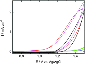
To assess the WOC performances of the LB and DC films, along with films of the individual drop-cast components ([Ru(1)3][PF6]2 and Co4POM), cyclic voltammetry (CV) measurements were performed at pH 7.6 in phosphate buffer saline (PBS) solution in a three-electrode system (ESI†). Fig. 1 shows that the catalytic activity of the bare FTO-coated glass and the [Ru(1)3][PF6]2 drop cast film is negligible. In contrast, the Co4POM drop cast film exhibited larger current density than the LB and DC combined WOC ([Ru(1)3]2+/Co4POM) films. The onset of catalytic current of the DC film and Co4POM films occurs at nearly the same potential (+1.11 V and +1.13 V vs. Ag/AgCl, respectively), however, the current onsets at ∼0.1 V higher potential (+1.23 V vs. Ag/AgCl) in the case of LB films. The overpotential is at least 0.52 V over the thermodynamic potential for water oxidation at pH 7.6 (0.59 V vs. Ag/AgCl). The current density of 2.16 mA cm−2 is associated with the catalytic action of the combined [Ru(1)3][PF6]2/Co4POM system.
 | ||
| Fig. 1 CVs of 50-layer LB and DC films of [Ru(1)3][PF6]2/Co4POM on FTO (black and red curves respectively), DC films of [Ru(1)3][PF6]2 (blue) and Co4POM (magenta) on FTO, and bare FTO (green). Scan rate: 25 mV s−1. Complete CVs are shown in Fig. S5 (ESI†). | ||
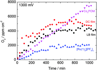
To monitor the amount of O2 evolved from the reaction between the [Ru(1)3][PF6]2/Co4POM system and H2O we have developed a closed cycle, recirculating gas chromatography (GC) system equipped with a custom-built, sealed electrochemical cell (Fig. S6, ESI†). A long term (over 1000 minutes) electrolysis was carried out by applying a constant potential of +1.3 V vs. Ag/AgCl (and +1.0 V vs. Ag/AgCl, see Fig. S7, ESI†) in PBS electrolyte. Sustainable O2 evolution was observed for ≈600 min for all four types of film, indicating the stability of the catalyst system on the FTO surface for a relative long time (Fig. 2). Although no further oxygen evolution was detected after 600 minutes from the LB and DC films or [Ru(1)3][PF6]2, the oxygen amount in the headspace steadily increased during the 1100 minutes for which the reaction was monitored above the Co4POM film. The DC films evolved slightly more O2 per area than the LB films. However, the thickness of the DC films is greater and the surface was more uneven than the layers prepared by the LB technique (Fig. S4 and S8, ESI†).
 | ||
| Fig. 2 O2 evolution vs. time at +1.3 V bias for LB and DC films prepared from [Ru(1)3][PF6]2 and Co4POM, and separate DC Co4POM and [Ru(1)3][PF6]2 films. | ||
Under a lower applied bias of +1 V vs. Ag/AgCl the DC, Co4POM and [Ru(1)3][PF6]2 films evolve approximately the same amount of O2 as at +1.3 V vs. Ag/AgCl bias (Fig. S7, ESI†) since the applied potentials are higher than their water oxidation onset potential. The LB film performs better at +1.3 V than at +1.0 V bias potential due to its higher onset potential of +1.23 V (Fig. S7, ESI†).
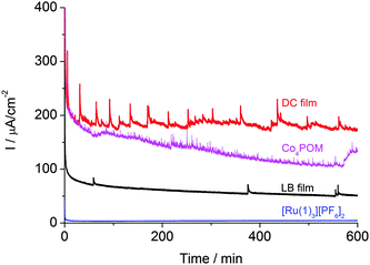
The long-term stability of the systems was confirmed by chronoamperometric measurements. A bias of +1.3 V (vs. Ag/AgCl) was applied for >600 minutes and the current was recorded under working conditions (Fig. 3). After the initial drop, the current was relatively stable. The spikes on the curves are due to bubble formation on, and desorption from the surface of the film. The results are similar to those for a study related to a spinel mixed oxide electrode.14 On the smoother surface of the LB films, fewer bubbles form than on the rough surface of the DC films. The height of the spikes scales with the observed current density.
 | ||
| Fig. 3 Current densities of LB and DC films, and DC Co4POM and [Ru(1)3][PF6]2 films during chronoamperometry (+1.3 V bias vs. Ag/AgCl). Spikes are caused by surface bubble formation. | ||
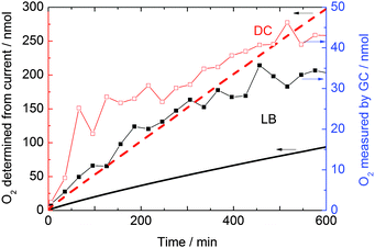
We compared the amount of evolved O2 measured by gas chromatography with the theoretical number of moles of O2 obtained from the current density data (shown in Fig. 3) applying Faraday's law (integrated current/4F) (Fig. 4).15 The amount of O2 determined from the GC experiment is around six times lower than that calculated for DC films and about one third of the theoretical value for LB films at 600 minutes. This can be attributed to the dissolution of O2 in the relatively large volume of electrolyte (59 cm3) compared to the 1 cm2 area of the electrode containing ∼3.5 nmol catalyst. The measured current density may also include parasitic side reactions. It is evident that the amount of catalyst material on the FTO substrate is lower after anodizing the electrodes for a significant period of time than in the initial DC and LB films (Fig. S8, ESI†). Initially, the electrodes show structures with a cracked pattern similar to the Co–Pi catalyst surface reported by Nocera.7 The post-electrochemical treated films show a very small amount of catalyst and the bare FTO surface is clearly visible in scanning electron microscopy (SEM) images (Fig. S8, ESI†) taken after 1000 min operation. However, the film thickness and surface structure remained the same after, (Fig. S1 and S2, ESI†), and the films were stable during, 1 h of catalytic activity.
The estimated amounts of Co4POM and [Ru(1)3][PF6]2 in the LB film are ≤3.5 nmol cm−2 and ≤1.5 nmol cm−2, respectively, and 1370 nmol cm−2 for the complexes in the DC film. From 1 cm2 LB and DC films, 34 and 43 nmol O2 evolved, respectively, in 600 minutes as measured by gas chromatography. The theoretical values for the same time interval, which were calculated from the current density data, are 94 and 298 nmol for 1 cm2 LB and DC films. Both measured and calculated values far exceed the amount that the stoichiometric reaction with water would give. The calculated turnover numbers and turnover frequencies for the LB and DC films are the following: TON = nO2/ncatalyst = 23 mol O2 per mol [Ru(1)3][PF6]2 or 10 mol O2 per mol Co4POM in 600 min for 1 cm2 LB films, and 0.03 mol O2 per mol complex on 1 cm2 DC films; TOF = nO2/ncatalyst = 0.0006 mol O2 per s per mol [Ru(1)3][PF6]2 or 0.00028 mol O2 per s per mol Co4POM for 1 cm2 LB films, and 0.00005 mol O2 per s per mol complex on 1 cm2 DC films. The TOF is lower than the value reported6 for a similar WOC system used as a homogeneous catalyst (≥5 s−1). In contrast to homogeneous catalysis where all molecules contribute to the catalytic activity, heterogeneous catalysis only occurs at selected surface sites. This is a likely reason for the lower TOF. Our TOF value is comparable to that of 0.0007 s−1 calculated for the WOC formed in situ on the surface of an indium tin oxide electrode from Co2+ containing neutral aqueous phosphate solution.7 Although a TOF value was not reported in Nocera's7 work, it was possible to calculate9 the lower limit since the amount of catalyst was given.
Powders and films of [Ru(1)3][PF6]2 and Co4POM were studied by X-ray diffraction (XRD) to examine how they changed during film preparation. It is clear that the [Ru(1)3][PF6]2 powder and film contain ruthenium(III) metaphosphate, Ru(PO3)3, which has a triclinic structure and is built from Ru3+ ions and infinite [PO3−]∞ chains.16 The Co4POM powder and film contain K2CoWO2(PO4)2, which is a possible building block of the [Co4(H2O)2(PW9O34)2]10− polyoxometalate. Interestingly, in the DC film of the mixture of [Ru(1)3][PF6]2 and Co4POM, a third kind of peak appears which is a convolution of the Ru(PO3)3 and K2CoWO2(PO4)2 peaks. This suggests an interaction between the ruthenium complex and Co4POM occurs during film preparation. The XRD results also reveal the presence of CoO1.29 both in the DC and LB films. The XRD patterns of the films before and after electrocatalytic activity were also compared. Similar to the SEM images, the XRD results confirm the desorption of most of the films from the substrate during 1000 minutes catalytic activity. The occurrence of Co2p, W4f, Ru3p and N1s peaks in X-ray photoelectron spectroscopy (XPS) survey scans confirm the presence of both Co4POM and [Ru(1)3][PF6]2 in the films. For detailed XRD and XPS analysis see Fig. S9–S13 and Table S1 (ESI†) and accompanying text.
The DC films evolve about 10 nmol cm−2 more O2 than the LB films at +1.3 V applied bias potential. The onset potential for DC [Ru(1)3][PF6]2/Co4POM and DC Co4POM films is ≈0.1 V lower than for the LB [Ru(1)3][PF6]2/Co4POM films, possibly arising from the larger surface area with more catalytic sites on the island-like structure of the DC film shown on the SEM images (Fig. S8, ESI†). Although the Co4POM evolves less O2 during the first 500–700 minutes than the LB and DC [Ru(1)3][PF6]2/Co4POM system, it continues to produce a linearly increasing amount of O2 after the other two films have reached saturation. As significantly less Co4POM was observed on the electrode after electrolysis than before electrolysis, it appears that Co4POM worked in part as a homogeneous catalyst and also partially decomposed to CoOx, which is an effective WOC catalyst. An ongoing debate concerns the stability of Co4POM and whether the polyoxometalate or CoOx is the true catalyst in the homogeneous systems. The reaction conditions, (pH, bias potential, buffer and the concentration of the catalyst) have a huge impact on the stability of Co4POM.17 In the homogeneous system, not only water molecules but also the organic ligand of the Ru complex are oxidized, furthermore precipitates form from the Co4POM and Ru complex and Co4POM decomposes in phosphate buffer at neutral and basic pH values where the POM catalyst is most active. When the catalyst is immobilized on an electrode surface, desorption of the catalyst and oxidant/photosensitizer is also an issue.18 All of these parameters affect the stability of our catalytic system and contribute to the cessation of catalytic activity after 600 minutes. The detailed investigation of the stability of the system was not the scope of this study.
In conclusion, we have prepared two kinds of water oxidizing electrodes: (i) alternating, smooth Langmuir–Blodgett monolayers of abundant, inorganic Co4POM catalyst and [Ru(1)3][PF6]2 oxidant and (ii) also alternating, uneven drop cast layers of the two above mentioned components, both on FTO substrate. We have found that both electrodes are efficient oxygen evolving anodes at pH 8 and the DC film evolves slightly more O2 per geometrical area due to its higher surface area. The catalyst is stable on the FTO surface for about 500–600 minutes. In long term operation, the drop cast Co4POM catalyst on its own evolves more O2 than the [Ru(1)3][PF6]2/Co4POM combined layers, most likely because it is not stable on the FTO surface and works as a homogeneous catalyst in the electrolyte. The turnover frequency of the LB and DC electrodes is lower than that of the homogeneous system of the same components reported by Hill,6 however, it is higher than the turnover frequency reported for Co4POM forming in situ on the surface of indium tin oxide electrode.7 Potentially, the stability of the system could be enhanced in the future by improving the binding of the catalyst system to the substrate and the components to each other, avoiding phosphate buffer and using for example borate buffer and using as low as possible bias potential. Organic oxidant/photosensitiser should also be avoided but a viable inorganic component has not yet been developed.
We thank the Swiss National Science Foundation (http://p3.snf.ch/project-137868) R’Equip. (http://p3.snf.ch/project-121306), the European Research Council (Advanced Grant 267816 LiLo) and the University of Basel for financial support. Financial support for D. K. B. from the Swiss National Science Foundation (NanoTera project SHINE, 20NA21-145936) and for R. T. from the Marie Heim Vögtlin Foundation (http://p3.snf.ch/project-139698) are gratefully acknowledged. We thank Hongjin Lv (Emory University) for providing the Co4–POM complex. The sealed electrochemical cell was designed by K. Gajda-Schrantz and H. Altorfer at Empa.
Notes and references
- J. Chow, R. J. Kopp and P. R. Portney, Science, 2003, 302, 1528 CrossRef PubMed.
- K. Arifin, E. H. Majlan, W. R. W. Daud and M. B. Kassim, Int. J. Hydrogen Energy, 2012, 37, 3066 CrossRef CAS; L. Duan, F. Bozoglian, S. Mandal, B. Stewart, T. Privalov, A. Llobet and L. Sun, Nat. Chem., 2012, 4, 418 CrossRef PubMed; A. Thapper, S. Styring, G. Saracco, A. W. Rutherford, B. Robert, A. Magnuson, W. Lubitz, A. Llobet, P. Kurz, A. Holzwarth, S. Fiechter, H. de Groot, S. Campagna, A. Braun, H. Bercegol and V. Artero, Green, 2013, 3, 43 CrossRef.
- See for example: J. G. McAlpin, T. A. Stich, W. H. Casey and R. D. Britt, Coord. Chem. Rev., 2012, 256, 2445 CrossRef CAS; X. Liu and F. Wang, Coord. Chem. Rev., 2012, 256, 1115 CrossRef; G. Wang, Y. Ling, H. Wang, L. Xihong and Y. Li, J. Photochem. Photobiol., C, 2014, 19, 35 CrossRef; V. Balzani, A. Credi and M. Venturi, ChemSusChem, 2008, 1, 26 CrossRef PubMed.
- H. Yamazaki, A. Shouji, M. Kajita and M. Yagi, Coord. Chem. Rev., 2010, 254, 2483 CrossRef CAS; M. Yagi, A. Syouji, S. Yamada, M. Komi, H. Yamazaki and S. Tajima, Photochem. Photobiol. Sci., 2009, 8, 139 Search PubMed.
- H. Lv, Y. V. Geletii, C. Zhao, J. W. Vickers, G. Zhu, Z. Luo, J. Song, T. Lian, D. G. Musaev and C. L. Hill, Chem. Soc. Rev., 2012, 41, 7572 RSC.
- Q. Yin, J. M. Tan, C. Besson, Y. V. Geletii, D. G. Musaev, A. E. Kuznetsov, Z. Luo, K. I. Hardcastle and C. L. Hill, Science, 2010, 328, 342 CrossRef CAS PubMed; H. Lv, J. Song, Y. V. Geletii, J. W. Vickers, J. M. Sumliner, D. G. Musaev, P. Kögerler, P. F. Zhuk, J. Bacsa, G. Zhu and C. L. Hill, J. Am. Chem. Soc., 2014, 136, 9268 CrossRef PubMed.
- M. W. Kanan and D. G. Nocera, Science, 2008, 321, 1072 CrossRef CAS PubMed.
- W. J. Youngblood, S.-H. A. Lee, Y. Kobayashi, E. A. Hernandez-Pagan, P. G. Hoertz, T. A. Moore, A. L. Moore, D. Gust and T. E. Mallouk, J. Am. Chem. Soc., 2009, 131, 926 CrossRef CAS PubMed; P. K. Ghosh, B. S. Brunschwig, M. Chou, C. Creutz and N. Sutin, J. Am. Chem. Soc., 1984, 106, 4772 CrossRef; I. A. Weinstock, E. M. G. Barbuzzi, M. W. Wemple, J. J. Cowan, R. S. Reiner, D. M. Sonnen, R. A. Heintz, J. S. Bond and C. L. Hill, Nature, 2001, 414, 191 CrossRef PubMed.
- F. Jiao and H. Frei, Angew. Chem., Int. Ed., 2009, 48, 1841 CrossRef CAS PubMed.
- G. Sprintschnik, H. W. Sprintschnik, P. P. Kirsch and D. G. Whitten, J. Am. Chem. Soc., 1977, 99, 4947 CrossRef CAS.
- G. L. Gaines, Jr, P. E. Behnken and S. J. Valenty, J. Am. Chem. Soc., 1978, 100, 6549 CrossRef.
- J. Wu, L. Liao, W. Yan, Y. Xue, Y. Sun, X. Yan, Y. Chen and Y. Xie, ChemSusChem, 2012, 5, 1207 CrossRef CAS PubMed; X. Xiang, J. Fielden, W. Rodríguez-Cordoba, Z. Huang, N. Zhang, Z. Luo, D. G. Musaev, T. Lian and C. L. Hill, J. Phys. Chem. C, 2013, 117, 918 Search PubMed; F. M. Toma, A. Sartorel, M. Iurlo, M. Carraro, P. Parisse, C. Maccato, S. Rapino, B. R. Gonzalez, H. Amenitsch, T. Da Ros, L. Casalis, A. Goldoni, M. Marcaccio, G. Scorrano, G. Scoles, F. Paolucci, M. Prato and M. Bonchio, Nat. Chem., 2010, 2, 826 CrossRef PubMed; N. Anwar, A. Sartorel, M. Yaqub, K. Wearen, F. Laffir, G. Armstrong, C. Dickinson, M. Bonchio and T. McCormac, ACS Appl. Mater. Interfaces, 2014, 6, 8022 Search PubMed; S. M. Lauinger, J. M. Sumliner, Q. Yin, Z. Xu, G. Liang, E. N. Glass, T. Lian and C. L. Hill, Chem. Mater., 2015, 2, 5886 CrossRef; J. Fielden, J. M. Sumliner, N. Han, Y. V. Geletii, X. Xiang, D. G. Musaev, T. Lian and C. L. Hill, Chem. Sci., 2015, 6, 5531 RSC; M. Nagai, H. Sanpei and M. Shirakura, J. Mater. Chem., 2012, 22, 9222 RSC.
- N. S. Murray, J. A. Rudd, A.-C. Chamayou, E. C. Constable, C. E. Housecroft, M. Neuburger and J. A. Zampese, RSC Adv., 2014, 4, 11766 RSC.
- T. Maiyalagan, K. A. Jarvis, S. Therese, P. J. Ferreira and A. Manthiram, Nat. Commun., 2014, 5, 3949 CrossRef CAS PubMed.
- D. K. Bora, A. Braun, R. Erni, G. Fortunato, T. Graule and E. C. Constable, Chem. Mater., 2011, 23, 2051 CrossRef CAS.
- H. Fukuoka, H. Imoto and T. Saito, J. Solid State Chem., 1995, 119, 107 CrossRef CAS.
- See for example: J. J. Stracke and R. G. Finke, J. Am. Chem. Soc., 2011, 133, 14872 CrossRef CAS PubMed; M. Natali, S. Berardi, A. Sartorel, M. Bonchio, S. Campagna and F. Scandola, Chem. Commun., 2012, 48, 8808 RSC; J. J. Stracke and R. G. Finke, ACS Catal., 2013, 3, 1209 CrossRef; J. W. Vickers, H. Lv, J. M. Sumliner, G. Zhu, Z. Luo, D. G. Musaev, Y. V. Geletii and C. L. Hill, J. Am. Chem. Soc., 2013, 135, 14110 CrossRef PubMed; J. J. Stracke and R. G. Finke, ACS Catal., 2014, 4, 79 CrossRef.
- J. M. Sumliner, H. Lv, J. Fielden, Y. V. Geletii and C. L. Hill, Eur. J. Inorg. Chem., 2014, 635 CrossRef CAS.
Footnote |
| † Electronic supplementary information (ESI) available: Experimental details, O2 calibration/quantification; Scheme S1: structure of [Ru(1)3]2+; Fig. S1–S4, S8: SEM images; Fig. S5: complete CVs; Fig. S6: electrochemical reactor; Fig. S7: rate of O2 production under 1 V applied bias; Fig. S9–S13, Table S1: XRD and XPS. See DOI: 10.1039/c5cc09556e |
| This journal is © The Royal Society of Chemistry 2016 |

