 Open Access Article
Hcp cobalt nanocrystals with high magnetic anisotropy prepared by easy one-pot synthesis†
L.
Meziane
a,
C.
Salzemann
a,
C.
Aubert
b,
H.
Gérard
c,
C.
Petit
*a and
M.
Petit
*b
aSorbonne Universités, UPMC Univ Paris 06, MONARIS, UMR CNRS 8233, Case 52, 4 Place Jussieu, 75252 Paris Cedex 05, France. E-mail: christophe.petit@upmc.fr
bSorbonne Universités, UPMC Univ Paris 06, Institut Parisien de Chimie Moléculaire, UMR CNRS 8232, Case 229, 4 Place Jussieu, 75252 Paris Cedex 05, France. E-mail: marc.petit@upmc.fr
cSorbonne Universités, UPMC Univ Paris 06, Laboratoire de Chimie Théorique, UMR CNRS 7616, 4 Place Jussieu, 75252 Paris Cedex 05, France
First published on 19th October 2016
Abstract
Herein we describe the first synthesis of pure mono-disperse spherical hcp-nanocrystals ferromagnetic at room temperature. Our strategy, based on the simple combination of oleylamine and ClCo(PPh3)3, allows the one-pot synthesis of size-controlled hcp-nanocrystals. The size and shape of the nanocrystals can be tuned by varying the reaction time or the concentration.
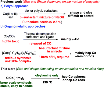
Recent studies have shown that nanocrystals (NCs) can play an important role in many different fields.1 In biology,2 they can be used in a new drug-delivery system2b or in hyperthermia treatment of cancer.2c In catalysis, NCs are applied in a wide range of reactions3 with different behaviors depending on the morphology.3a In magnetism,4 a wide range of applications can be found starting from the storage of information4a to nano-electronics and spintronics4d and also magnetocaloric materials, designing new alloys allowing cooling.5 Among these materials cobalt NCs are of particular interest due to their unique magnetic properties. Indeed cobalt NCs exist in three crystalline forms, hcp (hexagonal close-packed), fcc (face-centered cubic) and ε-cobalt; the first one being the most interesting in terms of magnetic properties due to its high magneto-crystalline anisotropy.6 Indeed, the use of magnetic nanoparticles for high density storage of information requires small nanoparticles with high magneto-crystalline anisotropy at usable temperature.4 Moreover, several publications relate the use of cobalt NCs in catalysis. However, to use such nanocrystals for these applications, in magnetism or catalysis, it is necessary to control the shape, size, phase and purity of the surfaces. Putzer published the first synthesis of hcp-Co reporting a shape control of the NPs in 1995.7 The authors described the synthesis of hcp-Co nanodisks by the decomposition of Co(OH)2 in basic aqueous media. Under such conditions, the formation of a cobalt oxide surface was impossible to eradicate and hence this synthesis was not further used. Nowadays, polyol synthesis of nanoparticles appears to be one of the “simplest” routes to prepare NPs involving the reduction of inorganic salt at high temperature (depending on the polyol).8 This is also the most representative approach of a complicated mixture synthesis of nanoparticles as variations in the polyols, cobalt salt, surfactant, even bi-surfactant mixture, and ruthenium seed additive allow us to obtain different shapes, sizes and phases (mainly fcc-Co and hcp-Co) of nanocrystals (Scheme 1a).9 However, in the last few decades, two other processes have been developed to produce mono-disperse Co NCs under milder conditions using Co(0 or I) organometallic precursors instead of inorganic salts (Scheme 1b). The first one is related to Carbonyl Metal Complexes (CMC) and their thermal decomposition to generate nanoparticles. For example, the thermolysis of Co2(CO)8 allows the formation of nanoparticles of different sizes and shapes depending on the surfactants/ligands present in the medium adopting mainly the new ε-cobalt phase.10
It is worth noting that “to obtain a pure fraction of hcp-Co disks containing no ε-spheres, it is necessary to physically separate the two populations after the reaction is quenched” as pointed by Puntes.11 The second one deals with Hydrocarbyl Complexes (HC) such as Co(η3-C8H13)(η4-C8H12) that readily decompose at lower temperature (around 150 °C) under dihydrogen pressure (usually 3 bars).12,13 Depending on the presence of a polyphenylenoxide polymer or a mixture of oleic acid, oleylamine, and more recently rhodamine, spherical,12 nanowires13 or disk-shaped14 hcp-Co NCs can be respectively obtained. However, if these two last conditions are milder with no reduction step, the use of carbon monoxide as a ligand (CMC approach) or hydrogen pressure (HC approach) still requires specific equipment in the laboratory.
Moreover, these organometallic precursors are not readily available on a large scale and often annealing is necessary to obtain pure hcp-Co phases.15
Thus, it is still a real challenge to develop a more simple synthesis procedure for pure hcp-Co nano-objects. Based on cobalt(II) salt and cobalt(0 or I) organometallic approaches, we decided to develop an in-between strategy. The idea is to use well-defined cobalt(I) halide complexes in the presence of oleylamine (OAm) which should act as a solvent, a surfactant and a reducing reagent (Scheme 1).16
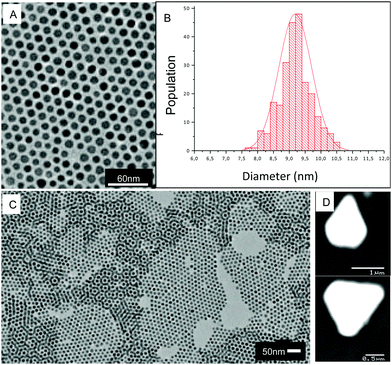
We chose to use the cobalt(I) complex ClCo(PPh3)3 which has several advantages over other organometallic precursors.17 Its synthesis can be carried out on a very large scale (more than 30 grams in our laboratory), using cheap and easy to handle reagents (triphenylphosphine: TPP, sodium-borohydride: NaBH4). Moreover ClCo(PPh3)3 is fairly stable in the solid state and can be synthesized and manipulated outside a glove-box. We first studied the synthesis of cobalt nanoparticles using the method of Sun16b with the cobalt(II) complex Cl2Co(PPh3)2 (entry 1, Table 1) or with the cobalt(I) complex ClCo(PPh3)3 (entry 2, Table 1) in OAm at 190 °C. The Co(II) complex did not form any nanoparticles as already observed by Sun with Co(acac)2. However, using the analog Co(I) complex, after 1 hour we observed the formation of spherical shaped monodisperse Co-NCs as confirmed by Transmission Electron Microscopy, TEM (Fig. 1). These two first results suggest that oleylamine is a too weak reducing reagent for the cobalt(II) salt, but enough for the cobalt(I) complex. In order to reduce the reaction temperature, we tried to use the complex ClCo(PPh3)3 in the presence of more conventional reducing reagents (NaBH4 or NaBEt3H) and in the presence of oleylamine (OAm) or oleic acid (OAc) (entries 3–5, Table 1). However, in all the cases the formation of only polymorphic and polydisperse NPs was observed (see ESI Fig. S1†). It is surprising to note that NaBH4 is not reducing enough for the cobalt(I) complex when the solvent is OAm and no NPs can be formed even at 190 °C (entry 6). Hence, only the protocol described in entry 2 allows the formation of 9.2 nm spherical Co NPs, characterized by very low polydispersity of 6% (Fig. 1A and B). This NP size distribution favors self-organization in a long range 2D hexagonal ordering (Fig. 1A) and thin 3D assemblies (Fig. 1C) as obtained by simply depositing a drop of solution containing NPs onto amorphous carbon substrates. When a concentrated solution is allowed to slowly evaporate on a graphite substrate, well-developed supracrystals sitting on their larger flat facets are observed (Fig. 1D). This is the characteristic of the formation of the so called “supracrystals” resulting from the 3D periodic arrangement of the nanocrystals either in fcc or hcp organization.18,19
| Entry | Co source | Reducing reagent | T (°C) | Solvent | Surfactant | NPsa |
|---|---|---|---|---|---|---|
| a All synthesis were run for 1 hour. b Monodispersity (MD) was observed by TEM. c Polydispersity (PD) was observed by TEM. | ||||||
| 1 | Cl2Co(PPh3)2 | No | 190 | OAm | OAm | No |
| 2 | ClCo(PPh3)3 | No | 190 | OAm | OAm | MDb |
| 3 | ClCo(PPh3)3 | NaBEt3H | rt | Toluene | OAm | PDc |
| 4 | ClCo(PPh3)3 | NaBEt3H | rt | Toluene | OAc | PDc |
| 5 | ClCo(PPh3)3 | NaBH4 | rt | Toluene/water | OAc | PDc |
| 6 | Cl2Co(PPh3)2 | NaBH4 | 190 | OAm | OAm | No |
This is due to the attractive van der Waals interactions between the metallic core and the “chemical bonds” of self-assemblies resulting from the interdigitation of the ligand molecules.18 It should be noticed from Fig. 1A that the deduced interparticles distance is 4.1 nm, which drastically limits the interparticle interaction.20 As a consequence no aggregation occurs in the solvent or on the substrates during the deposition process. Indeed the 2D patterns are purely hexagonal and also the thin 3D patterns (Fig. 1A and C). In the case of dipole–dipole interaction non-close-packed superlattices are often observed,21 which is not the case here (Fig. 1 and 2A). Indeed, we can affirm that no aggregation occurs in solution due to dipolar interaction.
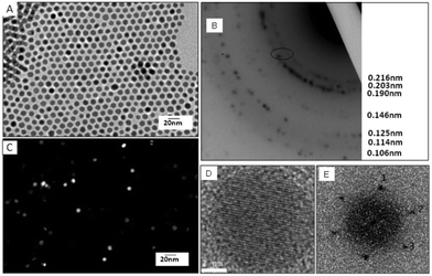
The structural characterization has been performed by TEM and high resolution TEM (Fig. 2). A typical electronic diffraction pattern (Fig. 2B) obtained for a collection of nanocrystals (Fig. 2A) consists of 7 diffraction rings characterized by 0.216 nm, 0.203 nm, 0.190 nm, 0.146 nm, 0.125 nm, 0.114 nm and 0.106 nm distances from the center to the outward ring, respectively.
These distances correspond to the (100), (002), (101), (102), (110), (103) and (201) planes of the hcp structure of cobalt metal, when compared with the bulk values (Table 2). It must be noted that the rings are constituted of a collection of spots typical of the different nanocrystal orientations. To determine the crystallinity of the Co NCs, a dark field image (Fig. 2C) corresponding to a bright field image (Fig. 2A) were compared on a collection of particles considering the first triplet of the hcp structure (i.e. corresponding to the (100), (002) and (101) planes). NCs not oriented in the Bragg direction appear black whereas the ones in the Bragg direction appear very bright. The fact that the NCs are uniformly bright or dark gives evidence of the monocrystallinity of the particles. The HRTEM image taken on individual nanocrystals exhibits three different lattice planes (Fig. 2D). This is well illustrated in the calculated power spectra which have three reflection pairs labeled 1, 2 and 3 (Fig. 2E). The deduced distances d1 = 0.220 nm and d2 = 0.198 nm ≈ d3 = 0.196 nm correspond to the {101} and {100} reflections of the hcp structure for lattice parameters (a = 0.254 nm and c = 0.416 nm) slightly higher than for bulk values (Table 2). Both lattice plane distances and the angle between the directions d1,d2 (63.3°) and d2,d3 (52.9°) are characteristic of hcp Co NCs in the [011] orientation. Thus, both the electron diffraction of a collection of NCs and the structural investigation of an individual NC confirm the formation of monocrystalline hcp Co NCs.
| h | k | l | dhkl(fcc) theoretical | dhkl(hcp) theoretical | dhkl(hcp) theoretical (2% of distortion) | dhkl(hcp) experimental |
|---|---|---|---|---|---|---|
| 1 | 0 | 0 | 2.171 | 2.200 | 2.20 | |
| 0 | 0 | 2 | 2.025 | 2.080 | 2.08 | |
| 1 | 0 | 1 | 1.916 | 1.945 | 1.95 | |
| 1 | 0 | 2 | 1.485 | 1.511 | 1.51 | |
| 1 | 1 | 0 | 1.254 | 1.270 | 1.24 | |
| 1 | 0 | 3 | 1.150 | 1.173 | 1.16 | |
| 2 | 0 | 0 | 1.086 | 1.100 | — | |
| 1 | 1 | 2 | 1.067 | 1.084 | 1.07 | |
| 1 | 1 | 1 | 2.046 | |||
| 2 | 0 | 0 | 1.772 | |||
| 2 | 2 | 0 | 1.253 | |||
| 3 | 1 | 1 | 1.069 | |||
Knowing the magnetic anisotropy of the hcp Co (K = 4.1 × 10⁵ J m−3), the superparamagnetic diameter of a spherical NC is given by  where Dspmcr is the superparamagnetic critical diameter and
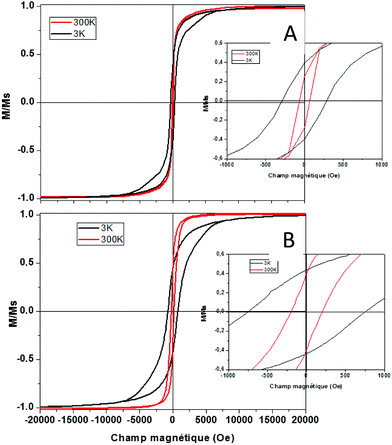
  is the volume of ferromagnetic particles obtained on SQUID apparatus at room temperature, T = 300 K.22 These estimations presume spherical particles with a very large measurement time compared to the Neel relaxation time of the magnetic nanocrystals. The case here is that SQUID measurements need about 60 s per point when the relaxation time is on a nanosecond scale.23 For hcp cobalt NCs, the deduced critical diameter is 8 nm, i.e. particles larger than 8 nm should be ferromagnetic at room temperature. This should be the case of the present 9.2 nm hcp cobalt nanocrystals. To confirm this assumption, magnetic measurements have been performed on the isolated nanocrystals dispersed in solution (i.e. without magnetic interactions). Typical M(H) curves are reported in Fig. 3 A at 3 K (black line) and 300 K (red line). They are normalized by the magnetization at saturation, Ms. Clearly an open hysteresis loop is observed, whatever the temperature, characteristic of a ferromagnetic behavior. The saturation is reached at 1 Tesla and, as expected, the coercive field (Hc) decreases with temperature (300 Oe at 3 K and 70 Oe at 300 K). This clearly confirms the ferromagnetic behavior, even at room temperature, of the 9.2 nm hcp-Co nanocrystals. Furthermore, the reduced remanence, Mr/Ms = M(H)/Ms at H = 0, is equal to 0.40 and is in good agreement with the expected value of 0.50 for spherical nanocrystals having a uniaxial anisotropy,24,25 which is the case of hcp-Co NCs. The value expected for spherical NCs with cubic anisotropy (case of fcc-Co NCs) is 0.83. The lower value obtained here (0.4 instead 0.5) is due to the surface effect (spin canting, passivating agent etc.) as generally observed for magnetic nanoparticles.26,27 The narrowing of the M(H) curve at H close to 0 should also be noticed. This effect is often observed in non-interacting magnetic nanoparticles and reflects the distribution of magnetic anisotropy mainly due to the size distribution or to various surface states.27,28
As the same nanoparticles are in interaction (i.e. assembled on a polymeric substrate (adhesive tape) by depositing several drops of toluene containing solution until complete evaporation), the M(H) curve is strongly modified as the Hc increases at 3 K to reach 760 Oe at 3 K and 208 Oe at 300 K. This is due to the dipolar interaction, due to the vicinity of the nanocrystals when they are agglomerated on the substrates compared to the case where they are isolated in solution. Furthermore, as the dipolar interactions are long range scale, the narrowing of the M(H) curve close to H = 0 is no more observed. This confirms the weakness of the magnetic interaction in the case of isolated cobalt NCs in solution.
We next studied if it was possible to tune the shape and the size of the cobalt NPs by varying simple parameters such as the concentration and reaction time. Reducing the concentration by a factor of two with the same temperature, 190 °C, and reaction time, 1 h, led to the formation of 7.8 nm Co NCs (6% of polydispersity) (see ESI Fig. S3A and B†). Crystallinity characterization proved that these smaller particles are also hcp-Co NPs (see ESI Fig. S2C†). Surprisingly,29 increasing the concentration (by a factor 2) did not allow the formation of bigger hcp-NPs. Formation of hcp-Co NPs of 9.1 nm was observed, suggesting that under such conditions (temperature and reaction time) a maximum size is reached (see ESI Fig. S3†). However, changing the reaction time from the standard conditions (Table 1, entry 2) has a tremendous effect. Indeed, by increasing the reaction time, a morphological transition occurs from spheres to rods with different aspects, the ratio depending on the reaction time (see ESI Fig. S4† and Fig. 4 after 540 minutes).
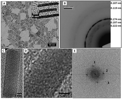 | ||
| Fig. 4 Structural characterization of cobalt nanorods (A) TEM image of cobalt nanorods, (B) electronic diffraction of cobalt nanorods, (C, D) HRTEM image and corresponding FFT (E). | ||
The electronic diffraction pattern (Fig. 4B) obtained for a collection of nanorods (Fig. 4A) consists of 5 diffractions rings. The rings characterized by 0.22 nm, 0.197 nm, 0.119 nm and 0.107 nm distances correspond to (101), (103) and (112) planes of the hcp structure of cobalt metal whereas the 0.174 nm distance can be attributed to the fcc cobalt structure. It has to be noted that the nanorods are very thin and few rods contribute to the electronic diffraction explaining the discrete diffuse rings consisting of spots. The HRTEM image of individual nanorods exhibits 3 different lattice planes (Fig. 4C and D). It is well illustrated in the calculated power spectra (Fig. 4E) which have three reflection pairs labeled 1, 2 and 3 characterized by distances d1 = 0.215 nm ≈ d2 = 0.216 nm and d3 = 0.141 nm corresponding to the {100} and {102} reflections of the hcp structure. However, in that case the crystal orientation is not clear at all. To further understand this unexpected morphological transition, wide angle and small angle X-ray scattering studies are in progress. Again, the magnetic characterization of isolated nanorods has been performed and a hysteresis loop is observed both at 300 K and 3 K, which confirms the presence of ferromagnetic nanorods. The coercive field, Hc as already observed, decreases with temperature (380 Oe at 3 K and 60 Oe at 300 K). The reduced remanence at 3 K is found to be equal to 0.7, when it decreases to 0.4 at 300 K. The higher value of Mr/Ms observed at 3 K for these uniaxial nanocrystals, compared to the expected value of 0.5 (ref. 24) or to the value obtained for the spherical NCs (0.4), could be due to a partial alignment of the nanorods with the applied magnetic field, when they are isolated in solution and thus allow one to move to follow the magnetic field.30 Thus, magnetic measurements clearly confirm the uniaxial anisotropy of the nanorods (Fig. 5).
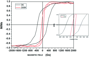 | ||
| Fig. 5 M(H) curve obtained for Co nanorods isolated in solution measured at 3 K (black line) and 300 K (red line). | ||
Conclusions
In conclusion we described herein a one-pot synthesis of hcp-cobalt NCs using the simple combination of an easily accessible well-defined cobalt(I) complex [ClCo(PPh3)3] and oleylamine. The resulting NCs have been well characterized and clearly are ferromagnetic at room temperature. This new gram-scalable synthesis allows one to control the size and the shape of magnetic nanocrystals depending only on the reaction conditions (time, concentration etc.). From an economical point of view, the obtention of a solution containing shape- and size-controlled ferromagnetic hcp-cobalt NCs opens a wide range of applications. Mechanistic studies for the formation of the NCs and the morphological transition are under progress.Acknowledgements
This work was supported by CNRS, MRES, UPMC and by the LabEx MiChem, part of French state funds managed by the ANR within the “Investissements d'Avenir” program under reference ANR-11-IDEX-0004-02 which we gratefully acknowledge. The subject matter described in the present article is covered by a patent application no. FR1562083.Notes and references
- (a) N. A. Frey, S. Peng, K. Cheng and S. Sun, Chem. Soc. Rev., 2009, 38, 2532 RSC; (b) K. Khan, S. Rehman, H. U. Rahman and Q. Khan, Synthesis and application of magnetic nanoparticles, in Nanomagnetism, ed. J. M. Gonzalez Estevez, One Central Press (OCP), UK, 2014, p. 135 Search PubMed; (c) Z. Nie, A. Petukhova and E. Kumacheva, Nat. Nanotechnol., 2010, 5, 15 CrossRef CAS PubMed.
- (a) K. M. Krisna, A. B. Pakomov, Y. Bao, P. Blomqvist, Y. Chun, M. Gonzales, K. Griffin, X. Ji and B. K. Roberts, J. Mater. Sci., 2006, 41, 793 CrossRef; (b) C. Sun, J. S. Lee and M. Zhang, Adv. Drug Delivery Rev., 2008, 60, 1252 CrossRef CAS PubMed; (c) F. Sonvico, S. Mornet, S. Vasseur, C. Dubernet, D. Jaillard, J. Degrouard, J. Hoebeke, E. Duguet, P. Colombo and P. Couvreur, Bioconjugate Chem., 2005, 16, 1181 CrossRef CAS PubMed.
- (a) L. Yong, L. Qiying and S. Wenjie, Dalton Trans., 2011, 40, 5811 RSC; (b) L. L. Chng, N. Erathodiyil and J. Y. Ying, Acc. Chem. Res., 2013, 46, 1825 CrossRef CAS PubMed; (c) A. Y. Khodakov, W. Chu and P. Fongarland, Chem. Rev., 2007, 107, 169 CrossRef PubMed; (d) S. W. Kim, S. U. Son, S. S. Lee, T. Hyeon and Y. K. Chung, Chem. Commun., 2001, 2212 RSC.
- (a) N. A. Frey and S. Sun, Magnetic Nanoparticle for Information Storage Applications, in Inorganic Nanoparticles: Synthesis, Applications, and Perspectives, ed. C. Altavilla and E. Ciliberto, CRC Press, 2010 Search PubMed; (b) G. C. Papaeftymiou, Nano Today, 2009, 4, 438 CrossRef; (c) A.-H. Lu, E. L. Salabas and F. Schuth, Angew. Chem., Int. Ed., 2007, 46, 1222 CrossRef CAS PubMed; (d) S. Karmakar, S. Kumar, R. Rinaldi and G. Maruccio, J. Phys.: Conf. Ser., 2011, 292, 012002 CrossRef.
- B. Podmiljsak, P. J. McGuiness, N. Mattern, H. Ehrenberg and S. Kobe, IEEE Trans. Magn., 2009, 45, 4364 CrossRef CAS.
- P. Gambardella, S. Rusponi, M. Veronese, D. D. Dhesi, C. Grazioli, A. Dallmeyer, I. Cabria, R. Zeller, P. H. Dederichs, K. Kern, C. Carbone and H. Brune, Science, 2003, 300, 1130 CrossRef CAS PubMed.
- C. P. Gibson and K. J. Putzer, Science, 1995, 267, 1338 CrossRef CAS PubMed.
- (a) F. Fievet, J. P. Lagier, B. Blin, B. Beaudoin and M. Figlarz, Solid State Ionics, 1989, 32/33, 198 CrossRef; (b) F. Boneta, V. Delmasa, S. Grugeona, R. H. Urbina, P. Y. Silverta and K. Tekaia-Elhsissena, Nanostruct. Mater, 1999, 11, 1277 CrossRef; (c) D. Larcher and R. J. Patrice, Solid State Chem., 2000, 154, 405 CrossRef CAS.
- (a) R. J. Joseyphus, T. Matsumoto, H. Takahashi, D. Kodama, K. Tohji and B. J. Jeyadevan, Solid State Chem., 2007, 180, 3008 CrossRef CAS; (b) C. W. Kim, H. G. Cha, Y. H. Kim, A. P. Jadhav, E. S. Ji and D. I. Kang, J. Phys. Chem. C, 2009, 113, 5081 CrossRef CAS; (c) S. I. Cha, C. B. Mo, K. T. Kim and S. H. Hong, J. Mater. Res., 2005, 20, 2148 CrossRef CAS; (d) Y. Soumare, C. Garcia, T. Maurer, G. Chaboussant, F. Ott, F. Fiévet, J.-Y. Piquemal and G. Viau, Adv. Funct. Mater., 2009, 19, 1971 CrossRef CAS.
- (a) F. S. Diana, S. H. Lee, P. M. Petroff and E. J. Kramer, Nano Lett., 2003, 3, 891 CrossRef CAS; (b) V. F. Puntes, K. M. Krishnan and A. P. Alivisatos, Science, 2001, 291, 2115 CrossRef CAS PubMed; (c) Y. Bao, W. An, C. Health Turner and K. M. Krishnan, Langmuir, 2010, 26(1), 478 CrossRef CAS PubMed.
- V. F. Puntes, D. Zanchet, C. K. Erdonmez and A. P. Alivisatos, J. Am. Chem. Soc., 2002, 124, 12874 CrossRef CAS PubMed.
- F. Dassenoy, M.-J. Casanove, P. Lecante, M. Verelst, E. Snoeck, A. Mosset, T. Ould Ely, C. Amiens and B. Chaudret, J. Chem. Phys., 2000, 112, 8137 CrossRef CAS.
- F. Dumestre, B. Chaudret, C. Amiens, M. C. Fromen, M. J. Casanove, P. Renaud and P. Zurcher, Angew. Chem., Int. Ed., 2002, 41, 4286 CrossRef CAS.
- M. Comesaña-Hermo, R. Estivill, D. Ciuculescu, Z.-A. Li, M. Spasova, M. Farle and C. Amiens, Langmuir, 2014, 30, 4474 CrossRef PubMed.
- (a) A. Demortière and C. Petit, J. Appl. Phys., 2012, 109, 084344 CrossRef; (b) S. Sun and C. B. Murray, J. Appl. Phys., 1999, 85, 4325 CrossRef CAS.
- (a) S. Mourdikoudis and M. L. Liz-Marzań, Chem. Mater., 2013, 25, 1465 CrossRef CAS; (b) Y. Yu, W. Yang, X. Sun, W. Zhu, X.-Z. Li, D. J. Sellmyer and S. Sun, Nano Lett., 2014, 14(5), 2778 CrossRef CAS PubMed.
- B. Cormary, F. Dumestre, N. Liakakos, K. Soulantica and B. Chaudret, Dalton Trans., 2013, 42, 12546 RSC.
- H. Brune, A. Court, C. Petit and V. Repain, Self-Assembly of Nanoalloys, in Nanoalloys: From Fundamentals to Emergent Applications, ed. F. Calvo, Elsevier, 2013, p. 373 Search PubMed.
- (a) M.-P. Pileni, Acc. Chem. Res., 2008, 41, 1799–1809 CrossRef CAS PubMed; (b) B. L. V. Prasad, C. M. Sorensen and K. J. Klabunde, Chem. Soc. Rev., 2008, 37, 1871–1883 RSC; (c) S. I. Stoeva, B. L. V. Prasad, S. Uma, P. K. Stoimenov, V. Zaikovski, C. M. Sorensen and K. J. Klabunde, J. Phys. Chem. B, 2003, 107, 7441–7448 CrossRef CAS.
- J. Richardi and J. J. Weis, J. Chem. Phys., 2013, 138, 244704 CrossRef CAS PubMed.
- D. Talapin, E. V. Shevchenko, C. B. Murray, A. V. Titov and P. Kraal, Nano Lett., 2007, 7, 1213–1219 CrossRef CAS PubMed.
- A. P. Guimaraes, in Principles of Nanomagnetism, Springer, 2009, p. 68 Search PubMed.
- M. Walker, P. I. Mayo, K. O'Grady, S. W. Charles and R. W. Chantrell, J. Phys.: Condens. Matter, 1993, 5, 2779 CrossRef.
- E. C. Stoner and E. P. Wohlfarth, IEEE Trans. Magn., 1991, 27, 3475 CrossRef CAS.
- I. Joffe and R. Heuberger, Philos. Mag., 1974, 314, 1051 CrossRef.
- J. P. Chen, C. M. Sorensen, K. J. Klabunde, G. C. Hadjipanayis, E. Devlin and A. Kostikas, Phys. Rev. B: Condens. Matter, 1996, 54, 9288 CrossRef CAS.
- C. Vázquez-Vázquez, M. A. López-Quintela, M. C. Buján-Núñez and J. Rivas, J. Nanopart. Res, 2011, 13, 1663 CrossRef.
- R. Morel, A. Brenac, C. Portemont, T. Deutsch and L. Notin, J. Magn. Magn. Mater., 2007, 308, 296 CrossRef CAS.
- A. T. Ngo and M. P. Pileni, J. Appl. Phys., 2002, 92, 4649 CrossRef CAS.
- C. B. Williamson, D. R. Nevers, T. Hanrath and R. D. Robinson, J. Am. Chem. Soc., 2015, 137, 15843 CrossRef CAS PubMed.
Footnote |
| † Electronic supplementary information (ESI) available. See DOI: 10.1039/c6nr05792f |
| This journal is © The Royal Society of Chemistry 2016 |

