 Open Access Article
Creative Commons Attribution 3.0 Unported Licence
Peripheral mechanism of a carbonyl hydrosilylation catalysed by an SiNSi iron pincer complex†
Toni T.
Metsänen‡
a,
Daniel
Gallego‡
a,
Tibor
Szilvási
b,
Matthias
Driess
*a and
Martin
Oestreich
 *a
*a
aInstitut für Chemie, Technische Universität Berlin, Straße des 17. Juni 115, 10623 Berlin, Germany. E-mail: matthias.driess@tu-berlin.de; martin.oestreich@tu-berlin.de
bDepartment of Inorganic and Analytical Chemistry, Budapest University of Technology and Economics, Szent Gellért tér 4, 1111 Budapest, Hungary
First published on 14th September 2015
Abstract
Combined experimental and theoretical analysis of the carbonyl hydrosilylation catalysed by an iron(0) pincer complex reveals an unprecedented mechanism of action. The iron(0) complex is in fact a precatalyst that is converted into an iron(II) catalyst through oxidative addition of a hydrosilane. Neither the hydrogen atom nor the silicon atom bound to the iron(II) centre are subsequently transferred onto the carbonyl acceptor, instead remaining at the sterically inaccessible iron(II) atom throughout the catalytic cycle. A series of labelling, crossover and competition experiments as well as the use of a silicon-stereogenic hydrosilane as a stereochemical probe suggest that the iron(II) site is not directly involved in the hydrosilylation. Strikingly, it is the silyl ligand attached to the iron(II) atom that acts as a Lewis acid for carbonyl activation in this catalysis. The whole catalytic process occurs on the periphery of the transition metal. Computation of the new peripheral as well as plausible alternative inner and outer sphere mechanisms support the experimental findings.
Introduction
Iron-catalysed carbonyl hydrosilylation can be traced back to seminal reports by Brunner1 but these contributions were decades ahead of their time. With few exceptions, catalyst development was focused on complexes of rare transition metals while limited progress had been made involving abundant transition metals. The pressing demand for sustainable processes finally shifted iron catalysis into the limelight,2 and several iron-based catalysts for carbonyl hydrosilylation with different ligand designs were introduced in recent years.3 The advent of these new catalysts immediately poses the question whether the mechanisms are similar to those established for rare transition-metal complexes or totally unprecedented.4 However, little detail is known about the mechanisms of action of iron complexes in catalytic hydrosilylation.Mechanisms of transition-metal-catalysed hydrosilylations exhibit a wide variety of modes of activation.5 However, the known mechanisms are characterised as either inner sphere6 where both the substrate and the hydrosilane are directly in contact with the metal or outer sphere7,8 where only one of the two is in contact with the metal centre. The proposed mechanisms for iron-catalysed hydrosilylations range from inner sphere mechanisms with σ-bond-metathesis-type Si–H bond cleavage at an iron–oxygen bond3k,3l to outer sphere mechanisms with iron acting as a Lewis acid,3h either activating the hydrosilane or the carbonyl group.
Driess and co-workers recently introduced silylenes as σ-donor ligands in iron-based catalysis, and iron(0) complexes 1 and 2 (Fig. 1) were applied to carbonyl hydrosilylation.9 Cooperativity between the iron(0) atom and the silicon(II) hydride in 1 was postulated to be relevant in the catalytic cycle.9a The SiNSi iron(0) pincer complex 2 was, in turn, believed to be a precatalyst9b,10 but a detailed mechanistic analysis remained challenging. We report here the disclosure of a unique mechanism of a transition-metal-catalysed carbonyl hydrosilylation that takes place neither inner nor outer sphere but on the periphery of the metal centre without its direct involvement.
Results and discussion
Optimisation and scope
The SiNSi pincer complex 2 (2.5 mol%) was found to catalyse the hydrosilylation of various acetophenones 3a–3i with silane 4a at elevated temperatures11 (Table 1, entries 1–9; see the ESI† for the optimisation of the reaction conditions). Both electron-donating (entries 1 and 3) as well as -withdrawing (entry 6) substituents at the aryl group were tolerated with the exception of a Et2N group in the para position (entry 2). The reaction was, however, sensitive toward steric hindrance. Substituents in the ortho position significantly lowered the yield (entries 7–9), and a 2,6-disubstituted substrate did not react (3j, entry 10). Benzophenone (3k, entry 11) reacted readily while propiophenone and isobutyrophenone (3l and 3m, entries 12 and 13) afforded 18 and 16% yield, respectively. Hydrosilylation of cyclopropyl substituted ketone (3n, entry 14) proceeded efficiently12 (see the ESI† for full scope).| Entry | 3 | R1 | R2 | Yield of 5b (%) | |
|---|---|---|---|---|---|
| a Reactions were performed on 0.10 mmol scale employing precatalyst 2 (2.5 mol%) and (EtO)3SiH (4a 1.5 equiv.). b Average yield from two runs determined by GLC-MS analysis and 1H NMR spectroscopy using anisole as internal standard. | |||||
| 1 | 3a |

|
X = MeO | Me | >99 (5a) |
| 2 | 3b | X = Et2N | Me | 40 (5b) | |
| 3 | 3c | X = Me | Me | 82 (5c) | |
| 4 | 3d | X = Br | Me | >99 (5d) | |
| 5 | 3e | X = H | Me | 93 (5e) | |
| 6 | 3f | X = CF3 | Me | 95 (5f) | |
| 7 | 3g |

|
X = MeO | Me | 70 (5g) |
| 8 | 3h | X = Me | Me | 70 (5h) | |
| 9 | 3i | X = Cl | Me | 49 (5i) | |
| 10 | 3j | Mes | Me | 0 (5j) | |
| 11 | 3k | Ph | Ph | 60 (5k) | |
| 12 | 3l | Ph | Et | 18 (5l) | |
| 13 | 3m | Ph | i-Pr | 16 (5m) | |
| 14 | 3n | c-Pr | Me | >99 (5n) | |
Isolation of the active catalyst
To gain insight into the mechanism, we investigated the reaction between iron(0) complex 2 and hydrosilanes 4a–c (2 → 7a–c, Scheme 1). Heating at 70 °C, a new set of distinct signals appeared in the 1H as well as in the 29Si and 31P NMR spectra. The 1H NMR spectrum clearly indicated the formation of an iron hydride, and detailed NMR analysis revealed that the hydride was likely to be trans to the apical phosphine ligand. The silyl group was assigned by 2D NMR experiments to be in the equatorial position trans to the pyridine ligand. We then obtained single crystals of 7b (Si = Me2PhSi) suitable for X-ray diffraction analysis, and that confirmed the molecular structure deduced from the NMR analysis. The structure shows a distorted octahedral iron(II) coordination environment. The hydride was located tilted toward one of the silylene donor arms deviated from the trans coordination to the Me3P ligand (P–Fe–H1 170.20(5)°), a situation similar to that of known iron(II) hydride pincer complexes.3h The Fe–Si bond distances 2.1509(7)/2.1715(7) Å for Fe–Si1/Si2 and 2.2986(8) for Fe–Si3 are within the range of iron silylene and silyl complexes.9a,13 The t-Bu groups encage the iron hydride with a Si1–Fe–Si2 angle far from the linearity, 144.54(3)°.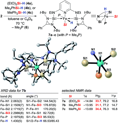 | ||
| Scheme 1 Identification of the catalytically active iron(II) complexes 7 from iron(0) precatalyst 2 and molecular structure of 7b. Hydrogen atoms except for the iron hydride are omitted for clarity. | ||
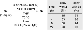
To validate whether the thus formed iron(II) complex 7 is the active catalyst, we measured the kinetic profiles for the hydrosilylation of 3a with hydrosilane 4a catalysed by 2 or 7a (Scheme 2). Conversion with 2 was only 15% after 1 h while the reaction had reached 74% with 7a. The reaction with 7a continued with significantly higher rate reaching 86% at 4 h compared to only 53% with 2. After 22 h, nearly full conversion is obtained for both. The greater initial rate of the catalysis with 7a strongly supports the assignment of the iron(II) complex 7 as the active catalyst.
Stoichiometric experiments: hydride transfer
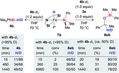
With the iron(II) hydrides 7 in hand, we had a closer look at the hydride transfer. Maintaining 7b and deuterium-labelled hydrosilane 4b-d1 in THF at 70 °C resulted in slow H/D exchange, visible both at the silicon and iron atoms (Scheme 3, left). The stoichiometric reaction between iron(II) hydride 7b, hydrosilane 4b-d1 (>95% deuteration grade), and ketone 3e was puzzling though (Scheme 3, right). Initially, the H![[thin space (1/6-em)]](https://www.rsc.org/images/entities/char_2009.gif) :
:![[thin space (1/6-em)]](https://www.rsc.org/images/entities/char_2009.gif) D ratio at the methine position of silyl ether 8eb is nearly 50
D ratio at the methine position of silyl ether 8eb is nearly 50![[thin space (1/6-em)]](https://www.rsc.org/images/entities/char_2009.gif) :
:![[thin space (1/6-em)]](https://www.rsc.org/images/entities/char_2009.gif) 50. However, it quickly decreases to 36
50. However, it quickly decreases to 36![[thin space (1/6-em)]](https://www.rsc.org/images/entities/char_2009.gif) :
:![[thin space (1/6-em)]](https://www.rsc.org/images/entities/char_2009.gif) 64 at 25% conversion within 6 hours and then gradually increases again, returning to 50
64 at 25% conversion within 6 hours and then gradually increases again, returning to 50![[thin space (1/6-em)]](https://www.rsc.org/images/entities/char_2009.gif) :
:![[thin space (1/6-em)]](https://www.rsc.org/images/entities/char_2009.gif) 50 at full conversion after a few days. Meanwhile, the corresponding reaction with partially deuterated 4b-d1 (ca. 50% deuteration grade) yielded 8eb with little deuterium incorporation at 19% conversion (H/D = 90
50 at full conversion after a few days. Meanwhile, the corresponding reaction with partially deuterated 4b-d1 (ca. 50% deuteration grade) yielded 8eb with little deuterium incorporation at 19% conversion (H/D = 90![[thin space (1/6-em)]](https://www.rsc.org/images/entities/char_2009.gif) :
:![[thin space (1/6-em)]](https://www.rsc.org/images/entities/char_2009.gif) 10). That ratio subsequently decreases to 78
10). That ratio subsequently decreases to 78![[thin space (1/6-em)]](https://www.rsc.org/images/entities/char_2009.gif) :
:![[thin space (1/6-em)]](https://www.rsc.org/images/entities/char_2009.gif) 22 to reach equilibrium after 24 hours. These results reveal that even though the hydride at the silicon atom in 4 is exchanging with the iron-bound hydride in 7, hydride transfer to the carbonyl carbon atom of 3 most likely occurs from the hydrosilane 4 and not from complex 7.14 Also, the reaction with partially deuterated hydrosilane indicates that the kinetic isotope effect (KIE) of the hydride transfer is significant. Precise value of the KIE could not be measured due to competing H/D exchanges (vide infra).
22 to reach equilibrium after 24 hours. These results reveal that even though the hydride at the silicon atom in 4 is exchanging with the iron-bound hydride in 7, hydride transfer to the carbonyl carbon atom of 3 most likely occurs from the hydrosilane 4 and not from complex 7.14 Also, the reaction with partially deuterated hydrosilane indicates that the kinetic isotope effect (KIE) of the hydride transfer is significant. Precise value of the KIE could not be measured due to competing H/D exchanges (vide infra).
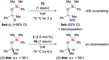
The possible H/D exchange at the methine position of silyl ether 8eb was verified using 8eb-d1 (Scheme 4, top). Treatment of 8eb-d1 with equimolar amounts of the iron(II) hydride 7b indeed led to H/D scrambling. Conversely, no erosion of the enantiomeric purity was seen when subjecting enantiopure silyl ether (S)-8eb to the typical protocol (precatalyst 2 and hydrosilane 4b generate catalyst 7b, Scheme 4, bottom). The configurational stability of (S)-8eb suggests that the hydride transfer itself is irreversible, and a concerted mechanism involving frontside attack at the asymmetrically substituted carbon atom is needed to explain the hydrogen atom exchange between the catalyst and the product.
These unusual scramblings were then investigated by DFT calculations.15 Both were found to proceed via a silylene-assisted concerted mechanism (9a‡ for Si–H and 10a‡ for C–H, Scheme 5) where the hydride on the iron atom is first shifted to the silicon atom of the adjacent donor-stabilised silylene ligand forming a pentacoordinate silicon atom16 while the Si–H or C–H bond interact with the now accessible iron centre. Both transition states are paired with their corresponding isomer where the second silylene ligand accepts the hydride. Attempts to locate the transient intermediates between the two degenerate conformations were not successful.
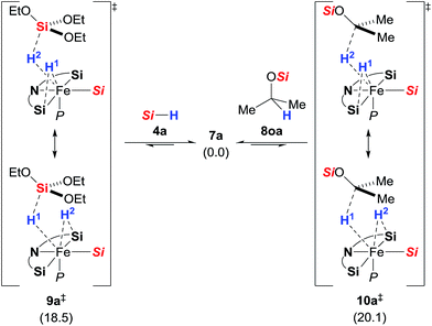 | ||
| Scheme 5 Silylene-assisted H/D scrambling at the hydrosilane silicon atom (9a‡, left) and the methine carbon atom (10a‡, right); Gibbs free energies given in parentheses in kcal mol−1; Si = Si(OEt)3. | ||
After the transition state, the silylene-bound hydrogen atom migrates back to the silicon and carbon atom, respectively. The activation barriers of the scrambling reactions (18.5 kcal mol−1 for Si–H and 20.1 kcal mol−1 for C–H) are energetically accessible under the reaction conditions.
Stoichiometric experiments: phosphine dissociation
To probe the potential lability of the phosphine, we performed phosphine crossover experiments. Slow exchange of the phosphine ligand with (CD3)3P (6-d9) was observed (Scheme 6, top left). When 7b was subjected to repeated reflux/freeze–pump–thaw cycles, we detected a new iron hydride species that was tentatively assigned as the expected phosphine-dissociated iron silyl hydride 11b-d6 with C6D6 as an η2-ligand (Scheme 6, top right). The generation of this new iron compound was accompanied by formation of disilane 12b and, with longer reaction times, decomposition into a complex mixture. The role of the disilane 12b in the formation of the complex 11b remains unexplained. Unfortunately, attempts to isolate 11b-d6 were unsuccessful. Its generation in the presence of acetophenone (3e) did not lead to the formation of the silyl ether 8eb (see the ESI† for details), providing further evidence against the role of 11 as an intermediate in the catalytic reaction. In fact, the dissociation of the Me3P (6) is significantly slower in the presence of ketone 3e. The formation 11 was also investigated computationally (Scheme 6, bottom). Phosphine dissociation from 7a gives energetically highly unfavoured intermediate cis-14a17 that readily coordinates benzene to form adduct 11a.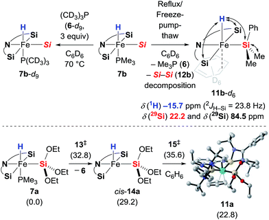 | ||
| Scheme 6 Phosphine scrambling and dissociation. Double-ended arrows in 11b-d6 show 1H, 29Si HMQC NMR correlation. Gibbs free energies given in parentheses in kcal mol−1 [Si = SiMe2Ph]. | ||
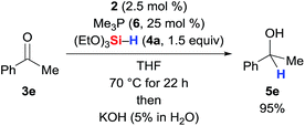
It must be noted here that catalysis with Guan's related iron(II) POCOP-pincer complex is thwarted by additional Me3P (6), indicating dissociation of one of the phosphine ligands as part of the catalytic cycle.3h When we added 25 mol% of Me3P (6, 10 equiv./catalyst) to the reaction mixture, the reaction was unaffected (Scheme 7, cf.Table 1, entry 5).
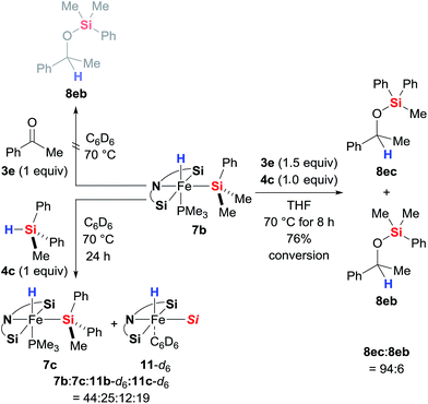
As is to be expected from the above observations, the hydride complex 7b did not produce any silyl ether 8eb when reacted stoichiometrically with ketone 3e in the absence of a hydrosilane (Scheme 8, top left). What was fascinating though is that the silyl ligand in 7b also remains untouched throughout the catalysis: 7b derived from Me2PhSiH (4b) catalyses the hydrosilylation of 3e with MePh2SiH (4c) with hardly any incorporation of the Me2PhSi moiety into the product; silyl ether 8ec rather than 8eb is formed almost exclusively (Scheme 8, right). This crossover experiment unequivocally proves that iron(II) complexes 7 are the actual catalysts, originating from oxidative addition of hydrosilanes 3 to the iron(0) complex 2; 2 is a precatalyst. During the crossover experiment no changes in the characteristic signals of complex 7b in the 1H and 31P NMR spectra were detected. However, when the assumed inability of 7b and 4c to exchange their silyl groups was examined with another control experiment (Scheme 8, bottom left), we observed slow exchange with ca. 36% conversion of 7b to 7c after 24 h. The Me2PhSi/MePh2Si scrambling was accompanied with formation of phosphine-dissociated, benzene-stabilised compounds 11b and 11c. Only traces of Me2PhSiH (4b) were observed, indicating that the exchange (7b to 7c) is in fact a side product of the decomposition rather than simple scrambling of the silyl groups.
Hydrosilylation with a silicon-stereogenic hydrosilane
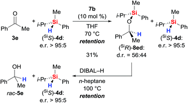
With sufficient knowledge of the active catalyst, we decided to analyse the stereochemical course at the silicon atom of the reacting hydrosilane (Scheme 9).18 Catalyst 7b promoted the reaction between highly enantioenriched hydrosilane (SiS)-4d (e.r. > 95![[thin space (1/6-em)]](https://www.rsc.org/images/entities/char_2009.gif) :
:![[thin space (1/6-em)]](https://www.rsc.org/images/entities/char_2009.gif) 5) and ketone 3e but conversion was slow as expected from the data obtained with achiral triorganosilane 4b (see Table S1, entry 12 in the ESI†). After 6 days, we were able to isolate the silyl ether (SiR)-8ed in 31% yield; diastereoselection was poor. The enantiomeric ratio of unreacted (SiS)-4d was found to be unaffected. Subsequent reductive cleavage of the Si–O bond in (SiR)-8ed (known to proceed with stereoretention at silicon atom19) liberated (SiS)-4d with overall retention of the stereochemistry at the silicon atom (e.r. > 95
5) and ketone 3e but conversion was slow as expected from the data obtained with achiral triorganosilane 4b (see Table S1, entry 12 in the ESI†). After 6 days, we were able to isolate the silyl ether (SiR)-8ed in 31% yield; diastereoselection was poor. The enantiomeric ratio of unreacted (SiS)-4d was found to be unaffected. Subsequent reductive cleavage of the Si–O bond in (SiR)-8ed (known to proceed with stereoretention at silicon atom19) liberated (SiS)-4d with overall retention of the stereochemistry at the silicon atom (e.r. > 95![[thin space (1/6-em)]](https://www.rsc.org/images/entities/char_2009.gif) :
:![[thin space (1/6-em)]](https://www.rsc.org/images/entities/char_2009.gif) 5). Hence, the hydrosilylation step involves frontside attack at the silicon atom, and that makes a mechanism involving Lewis-acid activation of the hydrosilane unlikely.18
5). Hence, the hydrosilylation step involves frontside attack at the silicon atom, and that makes a mechanism involving Lewis-acid activation of the hydrosilane unlikely.18
DFT calculation of conventional inner and outer sphere mechanisms15
Based on the combined findings, we propose that the active iron(II) catalyst 7 is generated from the iron(0) precatalyst 2 by oxidative addition of hydrosilane 4 to the zero-valent iron atom (Scheme 1). As expected due to the steric congestion around the iron(II) centre in 7a (grey box), we did not locate any structure resulting from direct insertion of the ketone C![[double bond, length as m-dash]](https://www.rsc.org/images/entities/char_e001.gif) O group into the iron hydride 7a or the silylene ligands (not shown). Instead, we were able to find a minimum structure for the phosphine-dissociated complex cis-14a (Scheme 10, left). In agreement with the experiments, cis-14a is however significantly higher in energy (29.2 kcal mol−1 relative to 7a). The intermediate cis-14a readily coordinates THF forming the adduct 17a. This intermediate is however a resting state if not a “mechanistic dead-end”. Ketone coordination to the iron centre of cis-14a gives intermediate 19oa with activated carbonyl group. The catalytic cycle is closed by an outer sphere concerted hydrosilane addition 20oa‡ to the ketone with an activation barrier of 33.7 kcal mol−1.
O group into the iron hydride 7a or the silylene ligands (not shown). Instead, we were able to find a minimum structure for the phosphine-dissociated complex cis-14a (Scheme 10, left). In agreement with the experiments, cis-14a is however significantly higher in energy (29.2 kcal mol−1 relative to 7a). The intermediate cis-14a readily coordinates THF forming the adduct 17a. This intermediate is however a resting state if not a “mechanistic dead-end”. Ketone coordination to the iron centre of cis-14a gives intermediate 19oa with activated carbonyl group. The catalytic cycle is closed by an outer sphere concerted hydrosilane addition 20oa‡ to the ketone with an activation barrier of 33.7 kcal mol−1.
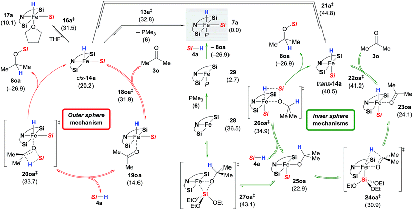 | ||
| Scheme 10 Alternative mechanisms. Gibbs free energies given in parentheses in kcal mol−1 [Si = Si(OEt)3]. | ||
Isomerisation of cis-14a to trans-14a was found to be strongly disfavoured, but again, ketone coordination to trans-14a lowered the energy significantly (Scheme 10, right). The following hydride transfer from 23oa passes through 24oa‡ (30.9 kcal mol−1) to afford the iron alkoxide 25oa. The silylated alcohol is released by an inner sphere silylation through 26oa‡ with an energy barrier of 34.9 kcal mol−1. An alternative inner sphere mechanism could be a reductive elimination from the intermediate 25oa. However, the energy barrier for the transition state 27oa‡ was found to be high, and the resulting iron(0) complex 28 is energetically disfavoured. Recoordination of phosphine 6 gives iron(0) complex 29 which oxidatively adds to a silane 4a to form 7a.
Peripheral mechanism: support from DFT calculations
In addition to the high energy barriers, neither outer nor inner sphere mechanisms give satisfactory fits to the experimental evidence. Hence, we looked for an adduct of 7a and 3o wherein the silyl group would act as a Lewis acid (Scheme 11).8,18,20 Coordination of the ketone to the silyl group via low energy transition state 30oa‡ (8.1 kcal mol−1) led to intermediate 31oa (2.8 kcal mol−1) with a pentacoordinate silicon atom, and the C![[double bond, length as m-dash]](https://www.rsc.org/images/entities/char_e001.gif) O double bond being significantly elongated compared to its equilibrium distance from 1.211 to 1.251 Å, indicating activation.21 Lewis pair formation is followed by coordination of hydrosilane 4a to the carbonyl group in 31oa, and the hydrosilylation event releases 8oa through transition state 32oa‡ with retention at the silicon atom. In accordance with our labelling experiments (cf.Scheme 3), this is the rate-determining step (14.3 kcal mol−1). To further validate this, we conducted a competition experiment between electron-rich 3a and electron-deficient 3f (Scheme 12). The para substitution in 3 exerts a pronounced electronic effect, and F3C-substituted 3f was consumed significantly faster than MeO-substituted 3a. This reactivity pattern is not unprecedented, and it has been seen previously in the activation of carbonyl compounds with silicon-based Lewis acids.22 The carbonyl carbon atom in 3f (X = CF3) is more positively polarised accelerating the hydride transfer, than that of donor-substituted 3a (X = OMe). The reactivity is also in agreement with the proposed KIE based on the control reactions with deuterated silane 4b-d1 (Scheme 3).
O double bond being significantly elongated compared to its equilibrium distance from 1.211 to 1.251 Å, indicating activation.21 Lewis pair formation is followed by coordination of hydrosilane 4a to the carbonyl group in 31oa, and the hydrosilylation event releases 8oa through transition state 32oa‡ with retention at the silicon atom. In accordance with our labelling experiments (cf.Scheme 3), this is the rate-determining step (14.3 kcal mol−1). To further validate this, we conducted a competition experiment between electron-rich 3a and electron-deficient 3f (Scheme 12). The para substitution in 3 exerts a pronounced electronic effect, and F3C-substituted 3f was consumed significantly faster than MeO-substituted 3a. This reactivity pattern is not unprecedented, and it has been seen previously in the activation of carbonyl compounds with silicon-based Lewis acids.22 The carbonyl carbon atom in 3f (X = CF3) is more positively polarised accelerating the hydride transfer, than that of donor-substituted 3a (X = OMe). The reactivity is also in agreement with the proposed KIE based on the control reactions with deuterated silane 4b-d1 (Scheme 3).
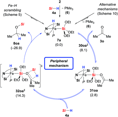 | ||
| Scheme 11 Peripheral mechanism. Gibbs free energies given in parentheses in kcal mol−1 [Si = Si(OEt)3]. | ||
Conclusions
The value of the present study is that it demonstrates, to our knowledge for the first time, an unusual case where the transition metal of a catalyst complex is not directly involved in the catalytic process. Activation of both substrate and reagent as well as the bond-forming and -breaking events happen in the ligand sphere, i.e., on the periphery of the transition metal. Coincidentally, the mechanism becomes outer sphere at silicon.22 The more conventional inner or outer sphere mechanisms do not apply to this unique catalyst.Acknowledgements
This research was supported by the Cluster of Excellence UniCat of the Deutsche Forschungsgemeinschaft (EXC 314/2). T.S. is grateful to The New Széchenyi Plan TAMOP-4.2.2/B-10/1-2010-0009. M.O. is indebted to the Einstein Foundation Berlin for an endowed professorship.Notes and references
- For the seminal work, see: H. Brunner and K. Fisch, Angew. Chem., Int. Ed. Engl., 1990, 29, 1131–1132 CrossRef.
- For reviews of iron-catalysed hydrosilylation, see: (a) K. Junge, K. Schröder and M. Beller, Chem. Commun., 2011, 47, 4849–4859 RSC; (b) M. Zhang and A. Zhang, Appl. Organomet. Chem., 2010, 24, 751–757 CrossRef CAS; (c) R. H. Morris, Chem. Soc. Rev., 2009, 38, 2282–2291 RSC.
- Selected reports include: (a) H. Nishiyama and A. Furuta, Chem. Commun., 2007, 760–762 RSC; (b) N. S. Shaikh, S. Enthaler, K. Junge and M. Beller, Angew. Chem., Int. Ed., 2008, 47, 2497–2501 CrossRef CAS PubMed; (c) B. K. Langlotz, H. Wadepohl and L. H. Gade, Angew. Chem., Int. Ed., 2008, 47, 4670–4674 CrossRef CAS PubMed; (d) A. M. Tondreau, J. M. Darmon, B. M. Wile, S. K. Floyd, E. Lobkovsky and P. J. Chirik, Organometallics, 2009, 28, 3928–3940 CrossRef CAS; (e) T. Inagaki, L. T. Phong, A. Furuta, J.-i. Ito and H. Nishiyama, Chem.–Eur. J., 2010, 16, 3090–3096 CrossRef CAS PubMed; (f) J. Yang and T. D. Tilley, Angew. Chem., Int. Ed., 2010, 49, 10186–10188 CrossRef CAS PubMed; (g) A. P. Dieskau, J.-M. Begouin and B. Plietker, Eur. J. Org. Chem., 2011, 5291–5296 CrossRef CAS; (h) P. Bhattacharya, J. A. Krause and H. Guan, Organometallics, 2011, 30, 4720–4729 CrossRef CAS; (i) A. J. Ruddy, C. M. Kelly, S. M. Crawford, C. A. Wheaton, O. L. Sydora, B. L. Small, M. Stradiotto and L. Turculet, Organometallics, 2013, 32, 5581–5588 CrossRef CAS; (j) Y. Sunada, H. Tsutsumi, K. Shigeta, R. Yoshida, T. Hashimoto and H. Nagashima, Dalton Trans., 2013, 42, 16687–16692 RSC; (k) H. Zhao, H. Sun and X. Li, Organometallics, 2014, 33, 3535–3539 CrossRef CAS; (l) Z. Zuo, H. Sun, L. Wang and X. Li, Dalton Trans., 2014, 43, 11716–11722 RSC; (m) T. Bleith, H. Wadepohl and L. H. Gade, J. Am. Chem. Soc., 2015, 137, 2456–2459 CrossRef CAS PubMed.
- For a mechanistic perspective, see: S. Chakraborty and H. Guan, Dalton Trans., 2010, 39, 7427–7436 RSC.
- J. Y. Corey, Chem. Rev., 2011, 111, 863–1071 CrossRef CAS PubMed.
- For selected examples of inner sphere hydrosilylation, see: (a) I. Ojima, M. Nihonyanagi, T. Kogure, M. Kumagai, S. Horiuchi, K. Nakatsugawa and Y. Nagai, J. Organomet. Chem., 1975, 94, 449–461 CrossRef CAS; (b) I. Ojima, T. Kogure, M. Kumagai, S. Horiuchi and T. Sato, J. Organomet. Chem., 1976, 122, 83–97 CrossRef CAS; (c) G. Z. Zheng and T. H. Chan, Organometallics, 1995, 14, 70–79 CrossRef CAS; (d) N. Schneider, M. Finger, C. Haferkemper, S. Bellemin-Laponnaz, P. Hofmann and L. H. Gade, Angew. Chem., Int. Ed., 2009, 48, 1609–1613 CrossRef CAS PubMed.
- For reviews of the related outer sphere hydrogenation, see: (a) O. Eisenstein and R. H. Crabtree, New J. Chem., 2013, 37, 21–27 RSC; (b) R. M. Bullock, Chem.–Eur. J., 2004, 10, 2366–2374 CrossRef CAS PubMed; (c) R. Noyori, M. Yamakawa and S. Hashiguchi, J. Org. Chem., 2001, 66, 7931–7944 CrossRef CAS PubMed.
- For outer sphere silane activation, see: (a) X.-L. Luo and R. H. Crabtree, J. Am. Chem. Soc., 1989, 111, 2527–2535 CrossRef CAS; (b) V. K. Dioumaev and R. M. Bullock, Nature, 2000, 424, 530–532 CrossRef PubMed; (c) E. A. Ison, E. R. Trivedi, R. A. Corbin and M. M. Abu-Omar, J. Am. Chem. Soc., 2005, 127, 15374–15375 CrossRef CAS PubMed; (d) G. Du, P. E. Fanwick and M. M. Abu-Omar, J. Am. Chem. Soc., 2007, 129, 5180–5187 CrossRef CAS PubMed; (e) D. V. Gutsulyak, S. F. Vyboishchikov and G. I. Nikonov, J. Am. Chem. Soc., 2010, 132, 5950–5951 CrossRef CAS PubMed; (f) S. Park and M. Brookhart, Organometallics, 2010, 29, 6057–6064 CrossRef CAS PubMed; (g) R. Lalrempuia, M. Iglesias, V. Polo, P. J. Sanz Miguel, F. J. Fernández-Alvarez, J. J. Pérez-Torrente and L. A. Oro, Angew. Chem., Int. Ed., 2012, 51, 12824–12827 CrossRef CAS PubMed; (h) T. T. Metsänen, P. Hrobárik, H. F. T. Klare, M. Kaupp and M. Oestreich, J. Am. Chem. Soc., 2014, 136, 6912–6915 CrossRef PubMed; (i) M. C. Lipke and T. D. Tilley, J. Am. Chem. Soc., 2014, 136, 16387–16398 CrossRef CAS PubMed; (j) M. Iglesias, F. J. Fernández-Alvarez and L. A. Oro, ChemCatChem, 2014, 6, 2486–2489 CrossRef CAS.
- (a) B. Blom, S. Enthaler, S. Inoue, E. Irran and M. Driess, J. Am. Chem. Soc., 2013, 135, 6703–6713 CrossRef CAS PubMed; (b) D. Gallego, S. Inoue, B. Blom and M. Driess, Organometallics, 2014, 33, 6885–6897 CrossRef CAS.
- K. J. Szabó and O. F. Wendt, Pincer and Pincer-Type Complexes: Applications in Organic Synthesis and Catalysis, Wiley-VCH, Weinheim, 2014 Search PubMed.
- For state-of-the-art iron catalysts operating at room temperature, see: (a) Ref. 3f ; (b) Ref. 3i ; (c) Ref. 3j ; (d) Ref. 3m .
- No ring opening of the cyclopropyl group was observed.
- (a) W. Yang, H. Fu, H. Wang, M. Chen, Y. Ding, H. W. Roesky and A. Jana, Inorg. Chem., 2009, 48, 5058–5060 CrossRef CAS PubMed; (b) Ref. 5 .
- O. G. Shirobokov, L. G. Kuzmina and G. I. Nikonov, J. Am. Chem. Soc., 2011, 133, 6487–6489 CrossRef CAS PubMed.
- All calculations were performed at ωB97X-D/6–31G(d)[Fe:cc-pVTZ] level of theory. Iron(II) complex 7a, triethoxysilane (4a), and acetone (3o) were used as model substrates. See the ESI† for full details.
- The calculated structures show in fact partial opening of the NHSi rings indicating formal oxidative addition taking place on the silicon(II) centre. For a review on non-innocent ligands, see: O. R. Luca and R. H. Crabtree, Chem. Soc. Rev., 2013, 42, 1440–1459 RSC.
- The complex cis-14a was calculated to be diamagnetic with vacant centre on the iron. The singlet-triplet gap was calculated to be only 5.1 kcal mol−1.
- (a) S. Rendler and M. Oestreich, Angew. Chem., Int. Ed., 2008, 47, 5997–6000 CrossRef CAS PubMed; (b) Ref. 8h .
- M. Oestreich, G. Auer and M. Keller, Eur. J. Org. Chem., 2005, 184–195 CrossRef CAS.
- During the preparation of this manuscript a neutral silicon Lewis acid catalysis was reported: A. L. Liberman-Martin, R. G. Bergman and T. D. Tilley, J. Am. Chem. Soc., 2015, 137, 5328–5331 CrossRef CAS PubMed.
- The adduct 31 was not observed by the 1H or 31P NMR spectroscopy, even at lower temperatures. Also attempts to perform a Gutmann–Beckett analysis with Et3PO led to only slight broadening of the 31P NMR resonance of the phosphine oxide..
- (a) K. Müther and M. Oestreich, Chem. Commun., 2011, 47, 334–336 RSC; (b) Ref. 20 .
Footnotes |
| † Electronic supplementary information (ESI) available: Experimental procedures and computational details, characterisation, crystallographic and quantum-chemical calculation data as well as NMR spectra. CCDC 1416378. For ESI and crystallographic data in CIF or other electronic format see DOI: 10.1039/c5sc02855h |
| ‡ These authors contributed equally. |
| This journal is © The Royal Society of Chemistry 2015 |


